Basisplattenkonstruktionsbeispiel mit AS 4100:2020, AS 3600:2018, AS 5216:2021
Problemanweisung
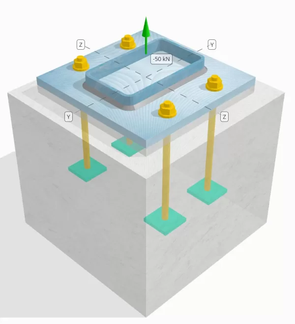
Bestimmen Sie, ob die konstruierte Säule-zu-Base-Plattenverbindung für eine Spannungsbelastung von 50 km ausreicht.
Gegebene Daten
Spalte:
Spaltenabschnitt: 250x150x8 rhs
Säulenbereich: 5920 mm2
Säulenmaterial: AS / NZS 1163 Gr. C350
Grundplatte:
Grundplattenabmessungen: 350 mmx 350 mm
Grundplattendicke: 20 mm
Grundplattenmaterial: AS / NZS 1163 Gr. C250
Fugenmörtel:
Fugenmörtel Dicke: 20 mm
Beton:
Konkrete Abmessungen: 450 mmx 450 mm
Betondicke: 400 mm
Betonmaterial: N28
Geknackt oder ungekrönt: Geknackt
Anker:
Ankerdurchmesser: 16 mm
Effektive Einbettungslänge: 250.0 mm
Einbettungsplattenbreite: 70 mm
Dicke eingebetteter Platten: 10 mm
Ankerversatz Abstand vom Gesicht der Säule: 62.5 mm
Schweißnähte:
Schweißtyp: Filet
Schweißkategorie: SP
Füllmetallklassifizierung: E43XX
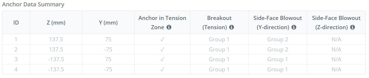
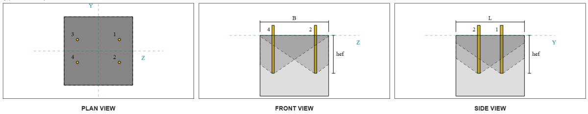
Ankerdaten (von Skyciv -Taschenrechner):
Modell im kostenlosen SkyCiv-Tool
Modellieren Sie noch heute das oben stehende Grundplattendesign mit unserem kostenlosen Online-Tool! Keine Anmeldung erforderlich.
Definitionen
Lastpfad:
Wenn eine Grundplatte einer Auftriebsausgabe ausgesetzt ist (zugfest) Kräfte, Diese Kräfte werden auf die Ankerstangen übertragen, was wiederum Biege Momente in der Grundplatte hervorruft. Die Biegeaktion kann als visualisiert werden als Beuge des Auslegers Um die Flansche oder das Netz des Spaltenabschnitts auftreten, abhängig davon, wo die Anker positioniert sind.
In dem SkyCiv Basisplatten-Design-Software, Nur Anker innerhalb der Ankerspannungszone werden als wirksam angesehen, um die Häufigkeit zu widerstehen. Diese Zone enthält typischerweise Bereiche in der Nähe der Spaltenflansche oder des Netzes. Für rechteckige Säulen, Die Ankerspannungszone bezieht sich auf den Bereich neben den Säulenwänden. Anker außerhalb dieser Zone tragen nicht zum Spannungswiderstand bei und sind von den Anhebungsberechnungen ausgeschlossen.
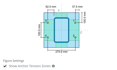
Um den effektiven Bereich der Grundplatte zu bestimmen, der sich der Biegung widersetzt, ein 45-Gradispersion wird von der Mittellinie jeder Ankerstange in Richtung der Säulenfläche angenommen. Diese Dispersion definiert die effektive Schweißlänge und hilft, die zu etablieren Effektive Biegebreite der Platte.
Die Annahme vereinfacht die Grundplattenanalyse, indem sie sich annähert, wie sich die Erhöhungskraft durch die Platte ausbreitet.
Ankergruppen:
Mit der SkyCiv Basisplatten-Design-Software Enthält eine intuitive Funktion, die identifiziert, welche Anker Teil einer Ankergruppe für die Bewertung sind Betonausbruch und Beton-Seitenflächen-Blowout Fehler.
Ein Ankergruppe besteht aus mehreren Ankern mit ähnlichen effektiven Einbettungstiefen und Abstand, und sind nah genug, dass ihre Projizierte Widerstandsbereiche überlappen sich. Wenn Anker gruppiert sind, Ihre Kapazitäten werden kombiniert, um der Gesamtspannungskraft zu widerstehen, die der Gruppe angewendet wird.
Anker, die die Gruppierungskriterien nicht erfüllen, werden als behandelt einzelne Anker. In diesem Fall, Nur die Spannungskraft am individuellen Anker wird gegen seinen eigenen wirksamen Widerstandsbereich überprüft.
Neugieriger Anstiegsfaktor:
Mit der SkyCiv Basisplatten-Design-Software beinhaltet eine Option zur Anwendung a neugieriger Anstiegsfaktor zusätzliche Zugkräfte auf den Ankern aufgrund von neugierigen Maßnahmen zu berücksichtigen. Dieser Faktor erhöht den Lastbedarf der Anker während der Ankerprüfungen, Bereitstellung einer konservativeren und realistischeren Bewertung gegebenenfalls zutreffend. Standardmäßig, Der neugierige Anstiegsfaktor ist auf 1.0, bedeutet, dass keine zusätzliche Prise -Last angewendet wird, sofern vom Benutzer nicht angegeben, sofern nicht angegeben.
Schritt-für-Schritt-Berechnungen:
Prüfen #1: Berechnen Sie die Schweißkapazität
Anwenden seismischer Lasten, Wir müssen die Last pro Anker und die effektive Schweißlänge pro Anker berechnen. Die effektive Schweißlänge wird durch die kürzeste Länge von der 45 ° -Ibranter bestimmt, eingeschränkt durch die tatsächliche Schweißlänge und den Ankerabstand.
Für diese Berechnung, Anker werden als beide klassifiziert Endanker oder Zwischenanker. Die Endanker befinden sich an den Enden einer Reihe oder einer Säule der Anker, während Zwischenanker zwischen ihnen positioniert sind. Die Berechnungsmethode unterscheidet sich jeweils und hängt von der Säulengeometrie ab. In diesem Beispiel, Es gibt zwei Anker im Internet, und beide werden als Endanker eingestuft.
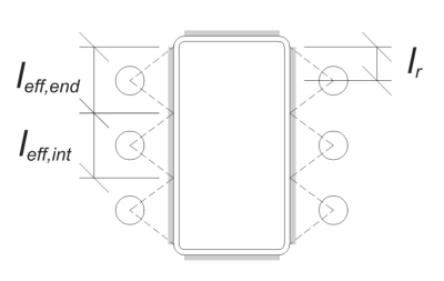
Für Endanker, Die effektive Schweißlänge ist durch den verfügbaren Abstand von der Ankermitte zur Säulen -Eckradius begrenzt. Die 45 ° Dispersion darf sich nicht über diese Grenze hinaus erstrecken.
\(
l_r = frac{d_{col} – 2t_{col} – 2r_{col} – S_ (N_{ein,\Text{Seite}} – 1)}{2} = frac{250 \, \Text{mm} – 2 \mal 8 \, \Text{mm} – 2 \mal 12 \, \Text{mm} – 150 \, \Text{mm} \mal (2 – 1)}{2} = 30 \, \Text{mm}
\)
Auf der inneren Seite, Die effektive Länge ist um die Hälfte des Ankerabstands begrenzt. Die insgesamt effektive Schweißlänge für den Endanker ist die Summe der äußeren und inneren Längen.
\(
l_{eff,Ende} = min links( Tun, 0.5 s_y rechts) + \min links( Tun, l_r rechts)
\)
\(
l_{eff,Ende} = min links( 62.5 \, \Text{mm}, 0.5 \mal 150 \, \Text{mm} \richtig) + \min links( 62.5 \, \Text{mm}, 30 \, \Text{mm} \richtig) = 92.5 \, \Text{mm}
\)
Für dieses Beispiel, Die endgültige effektive Schweißlänge für den Web -Anker wird als effektive Länge des Endankers angenommen.
\(
l_{eff} = l_{eff,Ende} = 92.5 \, \Text{mm}
\)
Als nächstes, Berechnen wir die Last pro Anker. Für einen bestimmten Satz von vier (4) Anker, Die Last pro Anker ist:
\(
T_{u,Anker} = frac{N_x}{N_{ein,t}} = frac{50 \, \Text{kN}}{4} = 12.5 \, \Text{kN}
\)
Unter Verwendung der berechneten effektiven Schweißlänge, Wir können jetzt die erforderliche Kraft pro Länge der Einheit berechnen, die auf die Schweißnaht wirkt.
\(
V^*_ W = Frac{T_{u,Anker}}{l_{eff}} = frac{12.5 \, \Text{kN}}{92.5 \, \Text{mm}} = 0.13514 \, \Text{kN / mm}
\)
Jetzt, wir werden verwenden AS 4100:2020 Klausel 9.6.3.10 Berechnung der Entwurfsstärke der Filetschweißung.
\(
\Phi v_w = phi 0.6 f_{Ihre} E_w k_r = 0.8 \mal 0.6 \mal 430 \, \Text{MPa} \mal 5.657 \, \Text{mm} \mal 1 = 1.1676 \, \Text{kN / mm}
\)
Neben der Überprüfung der Schweißnaht, Wir müssen auch das überprüfen Widerstand des Grundmetalls gegen die angewendete Spannungskraft, um sicherzustellen, dass sie den Fehlermodus nicht regiert.
\(
\phi v_{WBM} = phi links( \min links( F_{und _col} t_{col}, f_{und _bp} t_{bp} \richtig) \richtig)
\)
\(
\phi v_{WBM} = 0.9 \mal links( \min links( 350 \, \Text{MPa} \mal 8 \, \Text{mm}, 250 \, \Text{MPa} \mal 20 \, \Text{mm} \richtig) \richtig) = 2.52 \, \Text{kN / mm}
\)
In diesem Fall, Der Schweißwiderstand regelt über den Basismetallwiderstand.
Schon seit 0.13514 kN / mm < 1.1676 kN / mm, Die Schweißkapazität ist ausreichend.
Prüfen #2: Berechnen Sie die Kapazität der Grundplattenflexus aufgrund der Spannungsbelastung
Verwendung der Last pro Anker und die versetzte Entfernung von der Mitte des Ankers bis zur Säule der Säule (Als Lastzentrizität dienen), Der auf die Grundplatte angewendete Moment kann mit a berechnet werden Ausleger Annahme.
\(
M^* = t_{u,Anker} e = 12.5 \, \Text{kN} \mal 62.5 \, \Text{mm} = 781.25 \, \Text{kN} \CDOT Text{mm}
\)
Als nächstes, Verwenden der berechneten effektive Schweißlänge aus der vorherigen Überprüfung als Biegebreite, Wir können die berechnen SkyCiv Foundation ist ein Designmodul für die Gestaltung von Spreizfundamenten aus den Überbaulasten der Grundplatte verwenden AISC 360-22, Gleichung 2-1:
\(
\PHI M_S = PHI Z_{eff} f_{und _bp} = 0.9 \mal 9250 \, \Text{mm}^3 mal 250 \, \Text{MPa} = 2081.2 \, \Text{kN} \CDOT Text{mm}
\)
Wo,
\(
Z_{eff} = frac{l_{eff} (t_{bp})^ 2}{4} = frac{92.5 \, \Text{mm} \mal (20 \, \Text{mm})^ 2}{4} = 9250 \, \Text{mm}^ 3
\)
Schon seit 781.25 KN-MM < 2081.2 KN-MM, Die Grundkapazität der Grundplattenbiegung ist ausreichend.
Prüfen #3: Berechnen Sie die Ankerstange Zugkapazität
Um die zu bewerten Zugkapazität der Ankerstange, Wir beziehen uns auf AS 5216:2021 Klausel 6.2.2 und AS 4100:2020 Klausel 9.2.2.2.
Zuerst, Wir bestimmen die Zugspannungsbereich des Gewindeteils der Stange, folgende AS 4100:2020 Klausel 7.2 und Als 1275–1985 Klausel 1.7.
\(
A_n = frac{\Pi}{4} \links( \frac{d_a}{\Text{mm}} – 0.9382 P Right)^ 2 \, \Text{mm}^2 = Frac{\Pi}{4} \mal links( \frac{16 \, \Text{mm}}{1 \, \Text{mm}} – 0.9382 \mal 2 \richtig)^2 mal 1 \, \Text{mm}^2 = 156.67 \, \Text{mm}^ 2
\)
Verwenden von AS 4100:2020 Klausel 9.2.2, wir berechnen die Nennspannungskapazität des Bolzens basierend auf dem Zugspannungsbereich und der Materialfestigkeit.
\(
N_{tf} = A_n f_{U _anc} = 156.67 \, \Text{mm}^2 mal 800 \, \Text{MPa} = 125.33 \, \Text{kN}
\)
Wir wenden dann den entsprechenden Widerstandsfaktor an, um die zu erhalten Ankerkapazität in Spannung.
\(
\phi N_{Rk,s} = Phi n_{tf} = 0.8 \mal 125.33 \, \Text{kN} = 100.27 \, \Text{kN}
\)
Erinnern Sie sich an die zuvor berechneten Spannungsbelastung pro Anker, und wenden Sie die an neugieriger Anstiegsfaktor wenn angegeben.
\(
N^* = p links( \frac{N_x}{N_{ein,t}} \richtig) = 1 \mal links( \frac{50 \, \Text{kN}}{4} \richtig) = 12.5 \, \Text{kN}
\)
Schon seit 12.5 kN < 100.27 kN, bleibt die Ankerstabzugkapazität ist ausreichend.
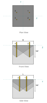
Prüfen #4: Berechnen Sie die Betonausbruchkapazität in der Spannung
Vor der Berechnung der Ausbruchkapazität, Wir müssen zuerst feststellen, ob das Mitglied als qualifiziert ist enges Mitglied. Gemäß AS 5216:2021 Klausel 6.2.3.8, Das Mitglied erfüllt die Kriterien für ein enges Mitglied. Deshalb, ein verändert Effektive Einbettungslänge muss in den Ausbruchkapazitätsberechnungen verwendet werden. Diese Anpassung beeinflusst auch die charakteristischer Abstand und charakteristische Kantenabstand, das muss entsprechend geändert werden.
Basierend auf den schmalen Mitgliedskriterien, bleibt die Modifizierte Werte Für die Ankergruppe sind wie folgt:
- modifizierte effektive Einbettungslänge, \(H'_{ef} = 100 \, \Text{mm}\)
- modifizierter charakteristischer Abstand, \(S'_{Einstellungen für Biege-Torsionsknicken} = 300 \, \Text{mm}\)
- modifizierter charakteristischer Kantenentfernung, \(C'_{Einstellungen für Biege-Torsionsknicken} = 150 \, \Text{mm}\)
Verwenden von AS 5216: 2021 Klausel 6.2.3.3, wir berechnen die Referenz projizierter Betonkegelbereich für einen einzelnen Anker.
\(
A0_{c,N.} = left( S'_{Einstellungen für Biege-Torsionsknicken,G1} \richtig)^2 = links( 300 \, \Text{mm} \richtig)^2 = 90000 \, \Text{mm}^ 2
\)
Ähnlich, wir berechnen die Tatsächlicher projizierter Betonkegelbereich der Ankergruppe.
\(
EIN_{Nc} = L_{Nc} B_{Nc} = 450 \, \Text{mm} \mal 450 \, \Text{mm} = 202500 \, \Text{mm}^ 2
\)
Wo,
\(
L_{Nc} = min links( c_{links,G1}, C'_{Einstellungen für Biege-Torsionsknicken,G1} + r_{einbetten _plate} \richtig) + \min links( S_{Summe,mit,G1}, S'_{Einstellungen für Biege-Torsionsknicken,G1} \cdot links( N_{mit,G1} – 1 \richtig) \richtig) + \min links( c_{richtig,G1}, C'_{Einstellungen für Biege-Torsionsknicken,G1} + r_{einbetten _plate} \richtig)
\)
\(
L_{Nc} = min links( 87.5 \, \Text{mm}, 150 \, \Text{mm} + 18 \, \Text{mm} \richtig) + \min links( 275 \, \Text{mm}, 300 \, \Text{mm} \Unterbau Erde (2 – 1) \richtig) + \min links( 87.5 \, \Text{mm}, 150 \, \Text{mm} + 18 \, \Text{mm} \richtig)
\)
\(
L_{Nc} = 450 \, \Text{mm}
\)
\(
B_{Nc} = min links( c_{oben,G1}, C'_{Einstellungen für Biege-Torsionsknicken,G1} + r_{einbetten _plate} \richtig) + \min links( S_{Summe,j,G1}, S'_{Einstellungen für Biege-Torsionsknicken,G1} \cdot links( N_{j,G1} – 1 \richtig) \richtig) + \min links( c_{Unterseite,G1}, C'_{Einstellungen für Biege-Torsionsknicken,G1} + r_{einbetten _plate} \richtig)
\)
\(
B_{Nc} = min links( 150 \, \Text{mm}, 150 \, \Text{mm} + 18 \, \Text{mm} \richtig) + \min links( 150 \, \Text{mm}, 300 \, \Text{mm} \Unterbau Erde (2 – 1) \richtig) + \min links( 150 \, \Text{mm}, 150 \, \Text{mm} + 18 \, \Text{mm} \richtig)
\)
\(
B_{Nc} = 450 \, \Text{mm}
\)
Mit der eingebettete Platte effektiver Radius wird verwendet, um eine zusätzliche Kapazität für Betonausbruch bereitzustellen. Um dies zu bestimmen, Fügen Sie die Dicke der eingebetteten Platte zur Hälfte des Ankerdurchmessers hinzu.
Als nächstes, Wir bewerten die charakteristische Stärke eines einzelnen Ankers verwenden AS 5216:2021 Gl. 6.2.3.2
\(
N0_{Rk,c} = k_1 sqrt{\frac{f’_c}{\Text{MPa}}} \links( \frac{H'_{ef,G1}}{\Text{mm}} \richtig)^{1.5} \, \Text{N.}
\)
\(
N0_{Rk,c} = 8.9 \mal sqrt{\frac{28 \, \Text{MPa}}{1 \, \Text{MPa}}} \mal links( \frac{100 \, \Text{mm}}{1 \, \Text{mm}} \richtig)^{1.5} \mal 0.001 \, \Text{kN} = 47.094 \, \Text{kN}
\)
Wo,
- \(k_{1} = 8.9\) für einbetonierte Anker
Jetzt, Wir bewerten die Auswirkungen der Geometrie, indem wir die erforderlichen Berechnung berechnen Parameter für Breakout -Widerstand.
Der kürzeste Randabstand der Ankergruppe wird als bestimmt als:
\(
c_{Min.,N.} = min links( c_{links,G1}, c_{richtig,G1}, c_{oben,G1}, c_{Unterseite,G1} \richtig) = min links( 87.5 \, \Text{mm}, 87.5 \, \Text{mm}, 150 \, \Text{mm}, 150 \, \Text{mm} \richtig) = 87.5 \, \Text{mm}
\)
Gemäß AS 5216:2021 Gl. 6.2.3.4, Der Wert für den Parameter zur Verteilung der Spannung in Beton ist:
\(
\Psi_{s,N.} = min links( 0.7 + 0.3 \links( \frac{c_{Min.,N.}}{C'_{Einstellungen für Biege-Torsionsknicken,G1}} \richtig), 1.0 \richtig) = min links( 0.7 + 0.3 \mal links( \frac{87.5 \, \Text{mm}}{150 \, \Text{mm}} \richtig), 1 \richtig) = 0.875
\)
Mit der Shell Spalling -Effekt wird zur Verwendung berücksichtigt AS 5216:2021 Gleichung 6.2.3.5, geben:
\(
\Psi_{Ausbruchkegelbereich für Einzeldübel nicht durch Kanten beeinflusst,N.} = min links( 0.5 + \frac{H'_{ef,G1}}{\Text{mm} \Unterbau Erde 200}, 1.0 \richtig) = min links( 0.5 + \frac{100 \, \Text{mm}}{1 \, \Text{mm} \Unterbau Erde 200}, 1 \richtig) = 1
\)
Zusätzlich, beide Exzentrizitätsfaktor und das Druckeinflussfaktor werden als:
\(
\Psi_{ec,N.} = 1
\)
\(
\Psi_{M.,N.} = 1
\)
Wir kombinieren dann all diese Faktoren und bewerben uns AS 5216:2021 Gleichung 6.2.3.1 Um die zu bewerten Konstruktionskegelausbruchwiderstand entwerfen Für die Ankergruppe:
\(
\phi N_{Rk,c} = phi_{Mc} N0_{Rk,c} \links( \frac{EIN_{Nc}}{A0_{c,N.}} \richtig) \Psi_{s,N.} \Psi_{Ausbruchkegelbereich für Einzeldübel nicht durch Kanten beeinflusst,N.} \Psi_{ec,N.} \Psi_{M.,N.}
\)
\(
\phi N_{Rk,c} = 0.6667 \mal 47.094 \, \Text{kN} \mal links( \frac{202500 \, \Text{mm}^ 2}{90000 \, \Text{mm}^ 2} \richtig) \mal 0.875 \mal 1 \mal 1 \mal 1 = 61.814 \, \Text{kN}
\)
Mit der Gesamtspannungsbelastung Auf der Ankergruppe wird berechnet, indem die Spannungsbelastung pro Anker mit der Anzahl der Anker multipliziert wird, mit dem neugierigen Anstiegsfaktor bei Bedarf:
\(
N^* = p links( \frac{N_x}{N_{ein,t}} \richtig) N_{ein,G1} = 1 \mal links( \frac{50 \, \Text{kN}}{4} \richtig) \mal 4 = 50 \, \Text{kN}
\)
Schon seit 50 kN < 61.814 kN Die Betonausbruchkapazität ist ausreichend.
Prüfen #5: Berechnen Sie die Ankerauszugskapazität
Mit der Ausziehkapazität eines Ankers wird durch den Widerstand an seinem eingebetteten Ende bestimmt. Zuerst, Wir berechnen die maximale Ankerkopfdimension, die für den Auszugswiderstand wirksam ist, gemäß AS 5216:2021 Klausel 6.3.4.
\(
d_{h,\Text{max}} = min links( = Abstand des Abschnitts, in dem die Scherung berücksichtigt wird, zur Fläche des nächsten Auflagers{einbetten _plate}, 6 \links( t_{einbetten _plate} \richtig) + d_a rechts) = min links( 70 \, \Text{mm}, 6 \mal (10 \, \Text{mm}) + 16 \, \Text{mm} \richtig) = 70 \, \Text{mm}
\)
Als nächstes, Wir berechnen die Netto -Lagerfläche der rechteckigen eingebetteten Platte mit:
\(
A_h = links( d_{h,\Text{max}}^2 rechts) – EIN_{Stange} = left( (70 \, \Text{mm})^2 rechts) – 201.06 \, \Text{mm}^2 = 4698.9 \, \Text{mm}^ 2
\)
Wo,
\(
EIN_{Stange} = frac{\Pi}{4} (d_a)^2 = Frac{\Pi}{4} \mal (16 \, \Text{mm})^2 = 201.06 \, \Text{mm}^ 2
\)
Wir berechnen dann die Entwerfen Sie grundlegende Ankerauszugsstärke mit AS 5216:2021 Klausel 6.3.4:
\(
N_{Rk,p} = phi_{Mc} K_2 a_h links( f'_c rechts) = 0.6667 \mal 7.5 \mal 4698.9 \, \Text{mm}^2 mal (28 \, \Text{MPa}) = 657.88 \, \Text{kN}
\)
Erinnern Sie sich an die zuvor berechneten Spannungsbelastung pro Anker:
\(
N^* = p links( \frac{N_x}{N_{ein,t}} \richtig) = 1 \mal links( \frac{50 \, \Text{kN}}{4} \richtig) = 12.5 \, \Text{kN}
\)
Schon seit 12.5 kN < 657.88 kN, Die Ankerauszugskapazität ist ausreichend.
Prüfen #6: Berechnen Sie die Blowout-Kapazität der Seitengesicht in der y-Richtung
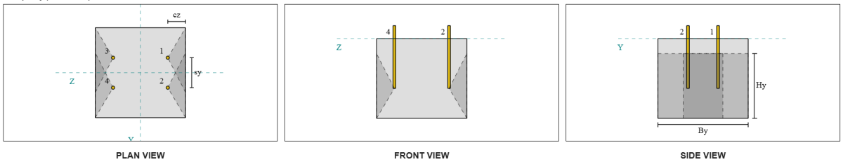
Betrachten wir die Blowout-Ankergruppe der Seitengesicht 1 Für die Kapazitätsberechnung. Bezieht sich auf die Zusammenfassung der Ankerdaten, Anker -IDs 3 und 4 sind Teil der SFY Group 1.
Wir beginnen mit der Berechnung des Kantenabstands zur Fehlerkante.
\(
c_{mit,\Text{Min.}} = min links( c_{\Text{links},G1}, c_{\Text{richtig},G1} \richtig) = min links( 87.5 \, \Text{mm}, 362.5 \, \Text{mm} \richtig) = 87.5 \, \Text{mm}
\)
Als nächstes, Wir bestimmen den Randabstand zum orthogonale Kante.
\(
c_{j,\Text{Min.}} = min links( c_{\Text{oben},G1}, c_{\Text{Unterseite},G1} \richtig) = min links( 150 \, \Text{mm}, 150 \, \Text{mm} \richtig) = 150 \, \Text{mm}
\)
Verwenden von AS 5216:2021 Klausel 6.2.7.3, Berechnen wir die Referenz projizierter Bereich eines einzelnen Befestigers.
\(
A0_{c,NB} = left( 4 c_{mit,\Text{Min.}} \richtig)^2 = links( 4 \mal 87.5 \, \Text{mm} \richtig)^2 = 122500 \, \Text{mm}^ 2
\)
Da wir die Kapazität der Ankergruppe überprüfen, Lass uns das bekommen Tatsächlicher projizierter Bereich der Ankergruppe verwenden AS 5216:2021 Klausel 6.2.7.2.
\(
EIN_{Nc} = B_{c,NB} Um es zu berechnen{c,NB} = 450 \, \Text{mm} \mal 325 \, \Text{mm} = 146250 \, \Text{mm}^ 2
\)
Wo,
\(
B_{c,NB} = min links( 2 c_{mit,\Text{Min.}}, c_{\Text{oben},G1} \richtig) + S_{\Text{Summe},j,G1} + \min links( 2 c_{mit,\Text{Min.}}, c_{\Text{Unterseite},G1} \richtig)
\)
\(
B_{c,NB} = min links( 2 \mal 87.5 \, \Text{mm}, 150 \, \Text{mm} \richtig) + 150 \, \Text{mm} + \min links( 2 \mal 87.5 \, \Text{mm}, 150 \, \Text{mm} \richtig) = 450 \, \Text{mm}
\)
\(
Um es zu berechnen{c,NB} = 2 c_{mit,\Text{Min.}} + \links( \min links( t_{\Text{konz}} – h_{\Text{ef}}, 2 c_{mit,\Text{Min.}} \richtig) \richtig)
\)
\(
Um es zu berechnen{c,NB} = 2 \mal 87.5 \, \Text{mm} + \links( \min links( 400 \, \Text{mm} – 250 \, \Text{mm}, 2 \mal 87.5 \, \Text{mm} \richtig) \richtig) = 325 \, \Text{mm}
\)
In der Berechnung der charakteristische konkrete Ausbruchstärke eines individuellen Ankers, wir werden verwenden AS 5216:2021 Klausel 6.2.7.2.
\(
N0_{Rk,cb} = k_5 links( \frac{c_{mit,\Text{Min.}}}{\Text{mm}} \richtig) \sqrt{\frac{Ah}{\Text{mm}^ 2}} \sqrt{\frac{f’_c}{\Text{MPa}}} \, N.
\)
\(
N0_{Rk,cb} = 8.7 \mal links( \frac{87.5 \, \Text{mm}}{1 \, \Text{mm}} \richtig) \mal sqrt{\frac{4698.9 \, \Text{mm}^ 2}{1 \, \Text{mm}^ 2}} \mal sqrt{\frac{28 \, \Text{MPa}}{1 \, \Text{MPa}}} \mal 0.001 \, \Text{kN}
\)
\(
N0_{Rk,cb} = 276.13 \, \Text{kN}
\)
Wo,
- \(k_{5} = 8.7\) für gerissenen Beton
- \(k_{5} = 12.2\) für ungekränkte Beton
Dann, Wir werden das bekommen Seitengesichtsparameter.
Der Parameter, der die Störung der Verteilung von Spannungen in Beton ausgeht, kann berechnet werden AS 5216:2021 Klausel 6.2.7.4.
\(
\Psi_{s,NB} = min links( 0.7 + 0.3 \links( \frac{c_{j,\Text{Min.}}}{2 c_{mit,\Text{Min.}}} \richtig), 1.0 \richtig)
\)
\(
\Psi_{s,NB} = min links( 0.7 + 0.3 \mal links( \frac{150 \, \Text{mm}}{2 \mal 87.5 \, \Text{mm}} \richtig), 1 \richtig) = 0.95714
\)
Die Gleichung von AS 5216:2021 Klausel 6.2.7.5 wird dann verwendet, um die Parameterrechnung für die zu erhalten Gruppeneffekt.
\(
\Psi_{G,NB} = max links( \sqrt{N_{j,G1}} + \links( 1 – \sqrt{N_{j,G1}} \richtig) \links( \frac{\min links( S_{j,G1}, 4 c_{mit,\Text{Min.}} \richtig)}{4 c_{mit,\Text{Min.}}} \richtig), 1.0 \richtig)
\)
\(
\Psi_{G,NB} = max links( \sqrt{2} + \links( 1 – \sqrt{2} \richtig) \mal links( \frac{\min links( 150 \, \Text{mm}, 4 \mal 87.5 \, \Text{mm} \richtig)}{4 \mal 87.5 \, \Text{mm}} \richtig), 1 \richtig)
\)
\(
\Psi_{G,NB} = 1.2367
\)
Schließlich, in Bezug auf AS 5216:2021 Gl. 6.2.7 Für Kopf -Ankerstangen, bleibt die Konstruktion konstruiere Ausbruchwiderstand ist:
\(
\phi N_{Rk,cb} = phi_m n0_{Rk,cb} \links( \frac{EIN_{Nc}}{A0_{c,NB}} \richtig) \Psi_{s,NB} \Psi_{G,NB} \Psi_{ec,N.}
\)
\(
\phi N_{Rk,cb} = 0.6667 \mal 276.13 \, \Text{kN} \mal links( \frac{146250 \, \Text{mm}^ 2}{122500 \, \Text{mm}^ 2} \richtig) \mal 0.95714 \mal 1.2367 \mal 1 = 260.16 \, \Text{kN}
\)
Für diese Ankergruppe, nur zwei (2) Anker gehören zur Gruppe. Deshalb, bleibt die Designspannungskraft denn die Ankergruppe ist:
\(
N^* = p links( \frac{N_x}{N_{ein,t}} \richtig) N_{j,G1}
\)
\(
N^* = 1 \mal links( \frac{50 \, \Text{kN}}{4} \richtig) \mal 2 = 25 \, \Text{kN}
\)
Schon seit 25 kN < 260.16 kN, Der Beton-Seitenflächen-Blowout entlang der Y-Region ist ausreichend.
Blowout-Ankergruppe für Seitengesicht 2 kann auch verwendet werden und liefert das gleiche Ergebnis, Da ist das Design symmetrisch.
Prüfen #7: Berechnen Sie die Blowout-Kapazität der Seitengesicht in der Z-Richtung
Diese Berechnung gilt nicht für den Fehler entlang der Z-Richtung, Da der Randabstand an den Seiten die Hälfte der effektiven Einbettungslänge überschreitet.
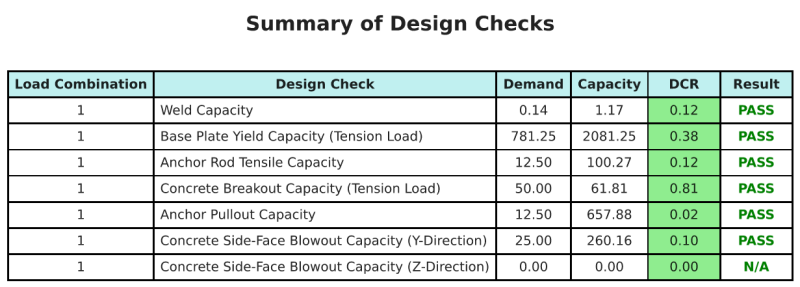
Entwurfszusammenfassung
Mit der Skyciv Base Plate Design Software kann automatisch einen Schritt-für-Schritt-Berechnungsbericht für dieses Entwurfsbeispiel erstellen. Es enthält auch eine Zusammenfassung der durchgeführten Schecks und deren resultierenden Verhältnisse, Die Informationen auf einen Blick leicht zu verstehen machen. Im Folgenden finden Sie eine Stichprobenzusammenfassungstabelle, Welches ist im Bericht enthalten.
SKYCIV -Beispielbericht
Sehen Sie sich den Detaillierungsgrad und die Klarheit an, die Sie von einem SkyCiv-Grundplatten-Designbericht erwarten können. Der Bericht umfasst alle wichtigen Designprüfungen, Gleichungen, und Ergebnisse werden in einem klaren und leicht lesbaren Format präsentiert. Es entspricht vollständig den Designstandards. Klicken Sie unten, um einen Beispielbericht anzuzeigen, der mit dem SkyCiv-Grundplattenrechner erstellt wurde.
Basisplattensoftware kaufen
Kaufen Sie die Vollversion des Basisplatten -Designmoduls selbst ohne andere Skyciv -Module selbst. Auf diese Weise erhalten Sie einen vollständigen Satz von Ergebnissen für die Basisplattendesign, Einbeziehung detaillierter Berichte und mehr Funktionen.