Basisplatten -Designbeispiel unter Verwendung von AISC 360-22 und ACI 318-19
Problemanweisung
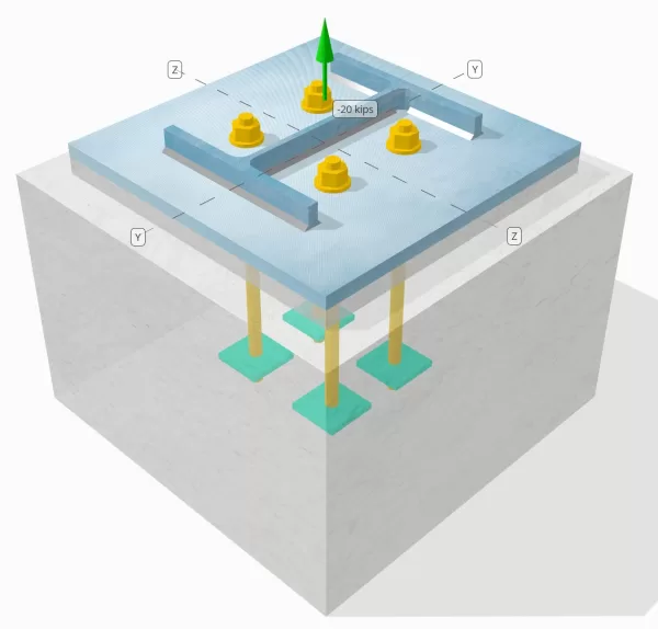
Stellen Sie fest, ob die geplante Verbindung zwischen Stütze und Grundplatte für eine Zuglast von 20 Kip ausreichend ist.
Gegebene Daten
Spalte:
Spaltenabschnitt: B12x53
Säulenbereich: 15.6 im2
Säulenmaterial: A992
Grundplatte:
Grundplattenabmessungen: 18 in x 18 im
Grundplattendicke: 3/4 im
Grundplattenmaterial: A36
Fugenmörtel:
Fugenmörtel Dicke: 1 im
Beton:
Konkrete Abmessungen: 22 in x 22 im
Betondicke: 15 im
Betonmaterial: 4000 psi
Geknackt oder ungekrönt: Geknackt
Anker:
Ankerdurchmesser: 3/4 im
Effektive Einbettungslänge: 12 im
Einbettungsplattenbreite: 3 im
Dicke eingebetteter Platten: 1/4 im
Abstand des Ankerversatzes von der Fläche des Stützenstegs: 2.8275 im
Schweißnähte:
Schweißnahtgröße: 1/4 im
Füllmetallklassifizierung: E70XX
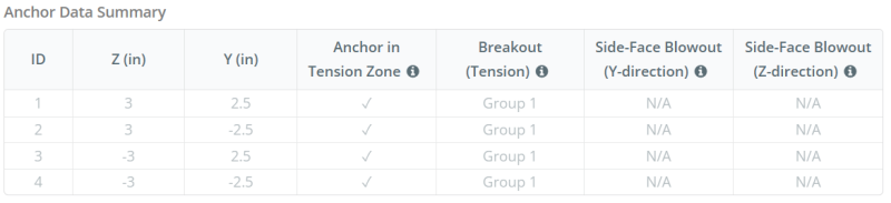
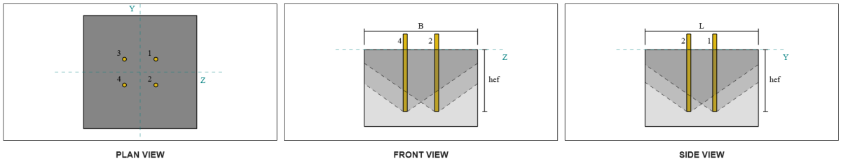
Ankerdaten (von Skyciv -Taschenrechner):
Modell im kostenlosen SkyCiv-Tool
Modellieren Sie noch heute das oben stehende Grundplattendesign mit unserem kostenlosen Online-Tool! Keine Anmeldung erforderlich.
Definitionen
Lastpfad:
Wenn eine Grundplatte einer Auftriebsausgabe ausgesetzt ist (zugfest) Kräfte, Diese Kräfte werden auf die Ankerstangen übertragen, was wiederum Biege Momente in der Grundplatte hervorruft. Die Biegeaktion kann als visualisiert werden als Beuge des Auslegers Um die Flansche oder das Netz des Spaltenabschnitts auftreten, abhängig davon, wo die Anker positioniert sind.
In dem SkyCiv Basisplatten-Design-Software, Nur Anker innerhalb der Ankerspannungszone werden als wirksam angesehen, um die Häufigkeit zu widerstehen. Diese Zone enthält typischerweise Bereiche in der Nähe der Spaltenflansche oder des Netzes. Anker außerhalb dieser Zone tragen nicht zum Spannungswiderstand bei und sind von den Anhebungsberechnungen ausgeschlossen.
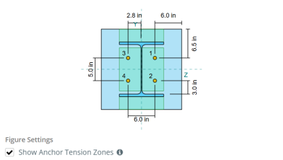
Um den effektiven Bereich der Grundplatte zu bestimmen, der sich der Biegung widersetzt, ein 45-Gradispersion wird von der Mittellinie jeder Ankerstange in Richtung der Säulenfläche angenommen. Diese Dispersion definiert die effektive Schweißlänge und hilft, die zu etablieren Effektive Biegebreite der Platte.
Die Annahme vereinfacht die Grundplattenanalyse, indem sie sich annähert, wie sich die Erhöhungskraft durch die Platte ausbreitet.
Ankergruppen:
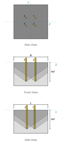
Mit der SkyCiv Basisplatten-Design-Software Enthält eine intuitive Funktion, die identifiziert, welche Anker Teil einer Ankergruppe für die Bewertung sind Betonausbruch und BetonseiteE-Face-Blowout Fehler.
Ein Ankergruppe besteht aus mehreren Ankern mit ähnlichen effektiven Einbettungstiefen und Abstand, und sind nah genug, dass ihre Projizierte Widerstandsbereiche überlappen sich. Wenn Anker gruppiert sind, Ihre Kapazitäten werden kombiniert, um der Gesamtspannungskraft zu widerstehen, die der Gruppe angewendet wird.
Anker, die die Gruppierungskriterien nicht erfüllen, werden als behandelt einzelne Anker. In diesem Fall, Nur die Spannungskraft am individuellen Anker wird gegen seinen eigenen wirksamen Widerstandsbereich überprüft.
Schritt-für-Schritt-Berechnungen
Prüfen #1: Berechnen Sie die Schweißkapazität
Anwenden seismischer Lasten, Wir müssen die Last pro Anker und die effektive Schweißlänge pro Anker berechnen. Die effektive Schweißnahtlänge wird durch die kürzeste Länge aus der Schweißnaht bestimmt 45° Streuung, eingeschränkt durch die tatsächliche Schweißlänge und den Ankerabstand.
Für diese Berechnung, Anker werden als beide klassifiziert Endanker oder Zwischenanker. Die Endanker befinden sich an den Enden einer Reihe oder einer Säule der Anker, während Zwischenanker zwischen ihnen positioniert sind. Die Berechnungsmethode unterscheidet sich jeweils und hängt von der Säulengeometrie ab. In diesem Beispiel, Es gibt zwei Anker im Internet, und beide werden als Endanker eingestuft.
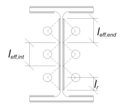
Für Endanker, Die effektive Schweißnahtlänge wird durch den verfügbaren Abstand von der Ankermittellinie zur Stützenkehle begrenzt. Die 45 ° Dispersion darf sich nicht über diese Grenze hinaus erstrecken.
\(
l_r = frac{d_{col} – 2t_f – 2r_{col} – S_(N_{ein,Seite} – 1)}{2} = frac{12.1 \, \Text{im} – 2 \mal 0.575 \, \Text{im} – 2 \mal 0.605 \, \Text{im} – 5 \, \Text{im} \mal (2 – 1)}{2} = 2.37 \, \Text{im}
\)
Auf der inneren Seite, Die effektive Länge ist um die Hälfte des Ankerabstands begrenzt. Die insgesamt effektive Schweißlänge für den Endanker ist die Summe der äußeren und inneren Längen.
\(
l_{eff,Ende} = min(Tun, 0.5S_) + \Min.(Tun, l_r)
\)
\(
l_{eff,Ende} = min(2.8275 \, \Text{im}, 0.5 \mal 5 \, \Text{im}) + \Min.(2.8275 \, \Text{im}, 2.37 \, \Text{im}) = 4.87 \, \Text{im}
\)
Für dieses Beispiel, bleibt die endgültige effektive Schweißnahtlänge Für den Steganker wird die wirksame Länge des Endankers angenommen.
\(
l_{eff} = l_{eff,Ende} = 4.87 \, \Text{im}
\)
Als nächstes, Berechnen wir die Last pro Anker. Für einen bestimmten Satz von vier (4) Anker, Die Last pro Anker ist:
\(
T_{u,Anker} = frac{N_x}{N_{ein,t}} = frac{20 \, \Text{kip}}{4} = 5 \, \Text{kip}
\)
Unter Verwendung der berechneten effektiven Schweißlänge, Das können wir jetzt bestimmen erforderliche Kraft pro Längeneinheit auf die Schweißnaht.
\(
r_u = frac{T_{u,Anker}}{l_{eff}} = frac{5 \, \Text{kip}}{4.87 \, \Text{im}} = 1.0267 \, \Text{kip/in}
\)
Jetzt, wir werden verwenden AISC 360-22, Kapitel J2.4 Berechnung der Entwurfsstärke der Filetschweißung.
Da es sich bei der aufgebrachten Last um eine reine Axialspannung handelt, der Winkel \(\Theta) wird als 90° angenommen, und der Richtungsfestigkeitskoeffizient kds wird nach berechnet AISC 360-22 Gl. J2-5.
\(
k_{ds} = 1.0 + 0.5(\ohne(\theta))^{1.5} = 1 + 0.5 \mal (\ohne(1.5708))^{1.5} = 1.5
\)
Schließlich, Wir werden uns bewerben AISC 360-22 Gl. J2-4 zu bestimmen Bemessungsfestigkeit der Kehlnaht pro Längeneinheit.
\(
\phi r_n = phi 0.6 F_{Exx} E_{w,Netz} k_{ds} = 0.75 \mal 0.6 \mal 70 \, \Text{KSI} \mal 0.177 \, \Text{im} \mal 1.5 = 8.3633 \, \Text{kip/in}
\)
Schon seit 1.0267 KPI < 8.3633 KPI, Die Schweißkapazität ist ausreichend.
Prüfen #2: Berechnen Sie die Kapazität der Grundplattenflexus aufgrund der Spannungsbelastung
Mit ter lädt pro Anker und der offset-Abstand von der Mitte des Ankers zur Stirnseite der Stütze (Als Lastzentrizität dienen), Der auf die Grundplatte angewendete Moment kann mit a berechnet werden Ausleger Annahme.
\(
M_u = T_{u,\Text{Anker}} e = 5 \, \Text{kip} \mal 2.8275 \, \Text{im} = 14.137 \, \Text{kip} \CDOT Text{im}
\)
Als nächstes, mit der Berechnungd effektive Schweißnahtlänge herm der vorherigen Prüfung als Biegebreite, Wir können die berechnen SkyCiv Foundation ist ein Designmodul für die Gestaltung von Spreizfundamenten aus den Überbaulasten der Grundplatte verwenden AISC 360-22, Gleichung 2-1:
\(
\phi M_n = phi F_{j,\Text{bp}} Z_{\Text{eff}} = 0.9 \mal 36 \, \Text{KSI} \mal 0.68484 \, \Text{im}^3 = 22.189 \, \Text{kip} \CDOT Text{im}
\)
Wo,
\(
Z_{\Text{eff}} = frac{l_{\Text{eff}} (t_{\Text{bp}})^ 2}{4} = frac{4.87 \, \Text{im} \mal (0.75 \, \Text{im})^ 2}{4} = 0.68484 \, \Text{im}^ 3
\)
Schon seit 14.137 Hühnchen < 22.189 Hühnchen, Die Grundkapazität der Grundplattenbiegung ist ausreichend.
Prüfen #3: Berechnen Sie die Ankerstange Zugkapazität
Bewertung der Zugkapazität der Ankerstange, wir werden verwenden ACI 318-19 Gleichung 17.6.1.2.
Zuerst, Wir bestimmen die angegebene Zugfestigkeit des Ankerstahls. Dies ist der niedrigste Wert, der von erlaubt ist ACI 318-19 Klausel 17.6.1.2, mit Bezug auf Materialeigenschaften in AISC 360-22 Tabelle J3.2.
\(
f_{\Text{uta}} = min links( 0.75 F_{u,\Text{anc}}, 1.9 F_{j,\Text{anc}}, 125 \richtig) = min links( 0.75 \mal 120 \, \Text{KSI}, 1.9 \mal 92 \, \Text{KSI}, 125.00 \, \Text{KSI} \richtig) = 90 \, \Text{KSI}
\)
Als nächstes, wir berechnen die Wirksamer Querschnittsbereich der Ankerstange. Dies basiert auf ACI 318-19 Kommentarklausel R17.6.1.2, was die Gewindegeometrie berücksichtigt. Die Anzahl der Fäden pro Zoll ergibt sich aus ASME B1.1-2019 Tabelle 1.
\(
EIN_{ich weiß,N.} = frac{\Pi}{4} \links( d_a – \frac{0.9743}{n_t} \richtig)^2 = Frac{\Pi}{4} \mal links( 0.75 \, \Text{im} – \frac{0.9743}{10 \, \Text{im}^{-1}} \richtig)^2 = 0.33446 \, \Text{im}^ 2
\)
Mit diesen Werten, Wir bewerben uns ACI 318-19 Gleichung 17.6.1.2 um die zu berechnen Zugfestigkeit auslegen der Ankerstange.
\(
\phi N_{zu} = phiA_{ich weiß,N.} f_{\Text{uta}} = 0.75 \mal 0.33446 \, \Text{im}^2 mal 90 \, \Text{KSI} = 22.576 \, \Text{kip}
\)
Erinnern Sie sich an die zuvor berechneten Spannungsbelastung pro Anker:
\(
N_{Tun} = frac{N_x}{N_{ein,t}} = frac{20 \, \Text{kip}}{4} = 5 \, \Text{kip}
\)
Schon seit 5 kip < 22.576 kip, Die Ankerstange -Zugkapazität ist ausreichend.
Prüfen #4: Berechnen Sie die Betonausbruchkapazität in der Spannung
Vor der Berechnung der Ausbruchkapazität, Wir müssen zuerst feststellen, ob das Mitglied als qualifiziert ist enges Mitglied. Gemäß ACI 318-19 Klausel 17.6.2.1.2, Das Mitglied erfüllt die Kriterien für ein enges Mitglied. Deshalb, Bei den Berechnungen muss eine modifizierte effektive Verankerungslänge verwendet werden.
Es wird festgestellt, dass die modifizierte effektive Einbettungslänge, h’ef, der Ankergruppe ist:
\(
H'_{\Text{ef}} = 5.667 \, \Text{im}
\)
Verwenden von ACI 318-19 Klausel 17.6.2, wir berechnen die Maximal projizierter Betonkegelbereich für einen einzelnen Anker, basierend auf der modifizierten effektiven Einbettungslänge.
\(
EIN_{N_{co}} = 9 \links( H'_{ef,G1} \richtig)^2 = 9 \mal links( 5.6667 \, \Text{im} \richtig)^2 = 289 \, \Text{im}^ 2
\)
Ähnlich, Wir verwenden die modifizierte effektive Einbettungslänge, um die zu berechnen Tatsächlicher projizierter Betonkegelbereich der Ankergruppe.
\(
EIN_{N_c} = min links( N_{ein,G1} EIN_{N_{co}}, L_{N_c} B_{N_c} \richtig) = min links( 4 \mal 289 \, \Text{im}^ 2, 22 \, \Text{im} \mal 22 \, \Text{im} \richtig) = 484 \, \Text{im}^ 2
\)
Wo,
\(
L_{N_c} = min links( c_{\Text{links},G1}, 1.5 H'_{\Text{ef},G1} \richtig)
+ \links( \min links( S_{\Text{Summe},mit,G1}, 3 H'_{\Text{ef},G1} \links( N_{mit,G1} – 1 \richtig) \richtig) \richtig)
+ \min links( c_{\Text{richtig},G1}, 1.5 H'_{\Text{ef},G1} \richtig)
\)
\(
L_{N_c} = min links( 8 \, \Text{im}, 1.5 \mal 5.6667 \, \Text{im} \richtig)
+ \links( \min links( 6 \, \Text{im}, 3 \mal 5.6667 \, \Text{im} \mal links( 2 – 1 \richtig) \richtig) \richtig)
+ \min links( 8 \, \Text{im}, 1.5 \mal 5.6667 \, \Text{im} \richtig)
\)
\(
L_{N_c} = 22 \, \Text{im}
\)
\(
B_{N_c} = min links( c_{\Text{oben},G1}, 1.5 H'_{\Text{ef},G1} \richtig)
+ \links( \min links( S_{\Text{Summe},j,G1}, 3 H'_{\Text{ef},G1} \links( N_{j,G1} – 1 \richtig) \richtig) \richtig)
+ \min links( c_{\Text{Unterseite},G1}, 1.5 H'_{\Text{ef},G1} \richtig)
\)
\(
B_{N_c} = min links( 8.5 \, \Text{im}, 1.5 \mal 5.6667 \, \Text{im} \richtig)
+ \links( \min links( 5 \, \Text{im}, 3 \mal 5.6667 \, \Text{im} \mal links( 2 – 1 \richtig) \richtig) \richtig)
+ \min links( 8.5 \, \Text{im}, 1.5 \mal 5.6667 \, \Text{im} \richtig)
\)
\(
B_{N_c} = 22 \, \Text{im}
\)
Als nächstes, Wir bewerten die Grundausbrechfestigkeit von Beton eines einzelnen Ankers verwenden ACI 318-19 Klausel 17.6.2.2.1
\(
N_b = k_c lambda_a sqrt{\frac{f’_c}{\Text{psi}}} \links( \frac{H'_{\Text{ef},G1}}{\Text{im}} \richtig)^{1.5} \, \Text{lbf}
\)
\(
N_b = 24 \mal 1 \mal sqrt{\frac{4 \, \Text{KSI}}{0.001 \, \Text{KSI}}} \mal links( \frac{5.6667 \, \Text{im}}{1 \, \Text{im}} \richtig)^{1.5} \mal 0.001 \, \Text{kip} = 20.475 \, \Text{kip}
\)
Wo,
- \(k_{c} = 24\) für einbetonierte Anker
- \(\lambda = 1.0 \) Für Normalgewicht Beton
Jetzt, Wir bewerten die Auswirkungen der Geometrie, indem wir die berechnen Kanteneffektfaktor und das Exzentrizitätsfaktor.
Der kürzeste Randabstand der Ankergruppe wird als bestimmt als:
\(
c_{ein,\Text{Min.}} = min links( c_{\Text{links},G1}, c_{\Text{richtig},G1}, c_{\Text{oben},G1}, c_{\Text{Unterseite},G1} \richtig)
= min links( 8 \, \Text{im}, 8 \, \Text{im}, 8.5 \, \Text{im}, 8.5 \, \Text{im} \richtig) = 8 \, \Text{im}
\)
Gemäß ACI 318-19 Klausel 17.6.2.4.1, der Ausbruch Kanteneffektfaktor ist:
\(
\Psi_{ed,N.} = min links( 1.0, 0.7 + 0.3 \links( \frac{c_{ein,\Text{Min.}}}{1.5 H'_{\Text{ef},G1}} \richtig) \richtig)
= min links( 1, 0.7 + 0.3 \mal links( \frac{8 \, \Text{im}}{1.5 \mal 5.6667 \, \Text{im}} \richtig) \richtig) = 0.98235
\)
Da die Zuglast im Schwerpunkt der Ankergruppe aufgebracht wird, die Exzentrizität ist Null. So, bleibt die Exzentrizitätsfaktor, auch von Klausel 17.6.2.4.1, ist:
\(
\Psi_{ec,N.} = min links( 1.0, \frac{1}{1 + \frac{2 und’_N}{3 H'_{\Text{ef},G1}}} \richtig)
= min links( 1, \frac{1}{1 + \frac{2 \mal 0}{3 \mal 5.6667 \, \Text{im}}} \richtig) = 1
\)
Zusätzlich, beide Rissfaktor und das Spaltfaktor werden als:
\(
\Psi_{c,N.} = 1
\)
\(
\Psi_{cp,N.} = 1
\)
Dann, Wir kombinieren all diese Faktoren und verwenden ACI 318-19 Gl. 17.6.2.1b Um die zu bewerten Betonausbrechfestigkeit der Ankergruppe:
\(
\phi N_{cbg} = phi links( \frac{EIN_{N_c}}{EIN_{N_{co}}} \richtig) \Psi_{ec,N.} \Psi_{ed,N.} \Psi_{c,N.} \Psi_{cp,N.} N_b
\)
\(
\phi N_{cbg} = 0.7 \mal links( \frac{484 \, \Text{im}^ 2}{289 \, \Text{im}^ 2} \richtig) \mal 1 \mal 0.98235 \mal 1 \mal 1 \mal 20.475 \, \Text{kip} = 23.58 \, \Text{kip}
\)
Mit der Gesamtspannungsbelastung auf die Ankergruppe ist das Produkt aus der Einzelankerlast und der Anzahl der Anker:
\(
N_{Tun} = left( \frac{N_x}{N_{ein,t}} \richtig) N_{ein,G1} = left( \frac{20 \, \Text{kip}}{4} \richtig) \mal 4 = 20 \, \Text{kip}
\)
Schon seit 20 Kips < 23.58 Kips, Die Betonausbruchkapazität ist ausreichend.
Prüfen #5: Berechnen Sie die Ankerauszugskapazität
Die Ausziehkapazität eines Ankers wird durch den Widerstand an seinem eingebetteten Ende bestimmt. Anwenden seismischer Lasten, Wir berechnen die Auflagefläche der eingebetteten Platte, Dies ist die Nettofläche nach Abzug der von der Ankerstange eingenommenen Fläche.
Für eine rechteckige eingebettete Platte, bleibt die Lagerfläche wird berechnet als:
\(
EIN_{brg} = left( \links( = Abstand des Abschnitts, in dem die Scherung berücksichtigt wird, zur Fläche des nächsten Auflagers{einbetten _plate} \richtig)^2 rechts) – EIN_{Stange} = left( \links( 3 \, \Text{im} \richtig)^2 rechts) – 0.44179 \, \Text{im}^2 = 8.5582 \, \Text{im}^ 2
\)
Wo,
\(
EIN_{Stange} = frac{\Pi}{4} \links( d_a rechts)^2 = Frac{\Pi}{4} \mal links( 0.75 \, \Text{im} \richtig)^2 = 0.44179 \, \Text{im}^ 2
\)
Als nächstes, Wir bestimmen die Grundauszugsfestigkeit des Ankers mit ACI 318-19 Gleichung 17.6.3.2.2a.
\(
N_b = 8 EIN_{brg} \links( f'_c rechts) = 8 \mal 8.5582 \, \Text{im}^2 Times links( 4 \, \Text{KSI} \richtig) = 273.86 \, \Text{kip}
\)
Wir wenden dann den entsprechenden Widerstandsfaktor an und Auszugsrissfaktor:
- Zum geknackt Beton, \(\Psi_{cp} = 1.0\)
- Zum ungerissen Beton, \(\Psi_{cp} = 1.4\)
Diese verwenden, Wir berechnen die Bestimmen Sie die Auszugsfestigkeit des Ankers unter Zug pro ACI 318-19 Gleichung 17.6.3.1.
\(
\phi N_{pn} = phi Psi_{c,p} N_b = 0.7 \mal 1 \mal 273.86 \, \Text{kip} = 191.7 \, \Text{kip}
\)
Erinnern Sie sich an die zuvor berechneten Spannungsbelastung pro Anker:
\(
N_{Tun} = frac{N_x}{N_{ein,t}} = frac{20 \, \Text{kip}}{4} = 5 \, \Text{kip}
\)
Schon seit 5 Kips < 191.7 Kips, Die Ankerauszugskapazität ist ausreichend.
Prüfen #6: Berechnen Sie die Biegekapazität der Einbettplatte
Dies ist eine ergänzende Prüfung, die mit dem durchgeführt wird Skyciv Base Plate Design Software um sicherzustellen, dass die eingebettete Platte über eine ausreichende Biegekapazität verfügt und unter den angewendeten Auszugslasten nicht nachgibt.
Zuerst, Wir bestimmen die Länge des freien (nicht unterstützt) Ende der eingebetteten Platte, gemessen von der Kante der Stütze bis zur Vorderseite der Stange.
\(
b’ = frac{= Abstand des Abschnitts, in dem die Scherung berücksichtigt wird, zur Fläche des nächsten Auflagers{einbetten _plate} – d_a}{2} = frac{3 \, \Text{im} – 0.75 \, \Text{im}}{2} = 1.125 \, \Text{im}
\)
Als nächstes, wir berechnen die Biegemoment wird durch den gleichmäßigen Lagerdruck induziert. Dieser Druck stellt die Kraft dar, die vom Ankerauszug auf die eingebettete Platte übertragen wird.
\(
m_f = \frac{\links( \frac{T_a}{EIN_{brg}} \richtig) \links( b’ \richtig)^ 2}{2} = frac{\links( \frac{5 \, \Text{kip}}{8.5582 \, \Text{im}^ 2} \richtig) \mal links( 1.125 \, \Text{im} \richtig)^ 2}{2} = 0.36971 \, \Text{kip}
\)
Schließlich, unter Verwendung des berechneten Moments und gegebener Materialeigenschaften, Wir werden das bestimmen minimal erforderliche Plattendicke widerstehen Biegenachgiebigkeit.
\(
t_{Min.} = Quadrat{\frac{4 m_w}{\PHI F_{y\_ep}}} = Quadrat{\frac{4 \mal 0.36971 \, \Text{kip}}{0.9 \mal 36 \, \Text{KSI}}} = 0.21364 \, \Text{im}
\)
Erinnern Sie sich an die tatsächliche Dicke der eingebetteten Platte:
\(
t_{tatsächlich} = t_{einbetten _plate} = 0.25 \, \Text{im}
\)
Schon seit 0.21364 im < 0.25 im, Die Biegekapazität der eingebetteten Platte beträgt ausreichend.
Prüfen #7: Berechnen Sie die Blowout-Kapazität der Seitengesicht in der y-Richtung
Diese Berechnung ist für dieses Beispiel nicht anwendbar, als die in angegebenen Bedingungen ACI 318-19 Klausel 17.6.4 werden nicht erfüllt. Deshalb, Es kommt nicht zu einem seitlichen Blowout-Fehler entlang der Y-Richtung.
Prüfen #8: Berechnen Sie die Blowout-Kapazität der Seitengesicht in der Z-Richtung
Diese Berechnung ist für dieses Beispiel nicht anwendbar, als die in angegebenen Bedingungen ACI 318-19 Klausel 17.6.4 werden nicht erfüllt. Deshalb, Es kommt nicht zu einem seitlichen Blowout-Fehler entlang der Z-Richtung.
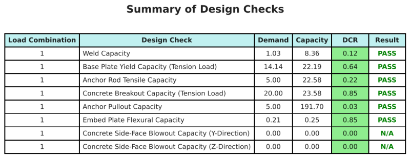
Entwurfszusammenfassung
Mit der Skyciv Base Plate Design Software kann automatisch einen Schritt-für-Schritt-Berechnungsbericht für dieses Entwurfsbeispiel erstellen. Es enthält auch eine Zusammenfassung der durchgeführten Schecks und deren resultierenden Verhältnisse, Die Informationen auf einen Blick leicht zu verstehen machen. Im Folgenden finden Sie eine Stichprobenzusammenfassungstabelle, Welches ist im Bericht enthalten.
SKYCIV -Beispielbericht
Sehen Sie sich den Detaillierungsgrad und die Klarheit an, die Sie von einem SkyCiv-Grundplatten-Designbericht erwarten können. Der Bericht umfasst alle wichtigen Designprüfungen, Gleichungen, und Ergebnisse werden in einem klaren und leicht lesbaren Format präsentiert. Es entspricht vollständig den Designstandards. Klicken Sie unten, um einen Beispielbericht anzuzeigen, der mit dem SkyCiv-Grundplattenrechner erstellt wurde.
Basisplattensoftware kaufen
Kaufen Sie die Vollversion des Basisplatten -Designmoduls selbst ohne andere Skyciv -Module selbst. Auf diese Weise erhalten Sie einen vollständigen Satz von Ergebnissen für die Basisplattendesign, Einbeziehung detaillierter Berichte und mehr Funktionen.