Exemplo de design da placa de base usando EN 1993-1-8:2005, EN 1993-1-1:2005, EN 1992-1-1:2004, e EN 1992-4:2018.
Declaração de problemas
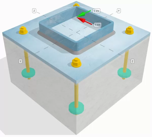
Determinar se a conexão de placa de coluna para base projetada é suficiente para um Você = 5-kN e VZ = 5-kN cargas de cisalhamento.
Dados dados
Coluna:
Seção de coluna: Shs 180x180x8
Área da coluna: 5440 milímetros2
Material da coluna: S235
Placa Base:
Dimensões da placa de base: 350 mm x 350 milímetros
Espessura da placa de base: 12 milímetros
Material da placa de base: S235
Grout:
Espessura do rejunte: 6 milímetros
Material de rejunte: ≥ 30 MPa
Concreto:
Dimensões concretas: 350 mm x 350 milímetros
Espessura do concreto: 350 milímetros
Material concreto: C25/30
Rachado ou sem crack: Rachado
Âncoras:
Diâmetro da âncora: 12 milímetros
Comprimento eficaz de incorporação: 150 milímetros
Diâmetro da placa incorporada: 60 milímetros
Espessura da placa incorporada: 10 milímetros
Material de ancoragem: 8.8
Outras informações:
- Âncoras não esbanjadoras.
- Âncora com fios cortados.
- K7 Factor para falha de cisalhamento de aço ancoradouro: 1.0
- Grau de restrição de fixador: Sem restrição
Soldas:
Tipo de solda: Solda de filete
Tamanho da perna de solda: 8milímetros
Classificação de metal de enchimento: E35
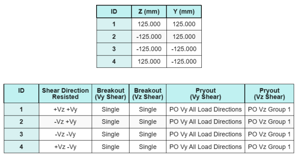
Dados de âncora (a partir de Calculadora Skyciv):
Modelo na ferramenta gratuita SkyCiv
Modele o design da placa de base acima usando nossa ferramenta online gratuita hoje mesmo! Não é necessária inscrição.
Definições
Caminho de carga:
A Software de design de placa de base SkyCiv segue EN 1992-4:2018 para design de haste de ancoragem. As cargas de cisalhamento aplicadas à coluna são transferidas para a placa de base através das soldas e depois para o concreto de apoio através das hastes de ancoragem. Fiction and Shear Lugs não são considerados neste exemplo, Como esses mecanismos não são suportados no software atual.
Grupos de âncora:
O software inclui um recurso intuitivo que identifica quais âncoras fazem parte de um grupo âncora para avaliar Breakout de cisalhamento de concreto e Pryout de cisalhamento de concreto falhas.
A grupo âncora é definido como duas ou mais âncoras com áreas de resistência projetadas sobrepostas. Nesse caso, as âncoras agem juntas, e sua resistência combinada é verificada contra a carga aplicada no grupo.
A âncora única é definido como uma âncora cuja área de resistência projetada não se sobrepõe a nenhum outro. Nesse caso, A âncora age sozinha, e a força de cisalhamento aplicada nessa âncora é verificada diretamente contra sua resistência individual.
Essa distinção permite que o software capture o comportamento do grupo e o desempenho individual da âncora ao avaliar os modos de falha relacionados ao cisalhamento.
Cálculos passo a passo
Verificar #1: Calcule a capacidade de solda
Assumimos que o Vz A carga de cisalhamento é resistida pelo soldas superior e inferior, enquanto o Vy A carga de cisalhamento é resistida exclusivamente pelo soldas esquerda e direita.
Para determinar a capacidade de solda do soldas superior e inferior, Primeiro calculamos o seu Comprimentos totais de solda.
\(
EU_{C,top\&figura inferior} = 2 \deixou(b_{col} – 2t_{col} – 2r_{col}\direito)
= 2 \times left(180 \,\texto{milímetros} – 2 \vezes 8 \,\texto{milímetros} – 2 \vezes 4 \,\texto{milímetros}\direito)
= 312 \,\texto{milímetros}
\)
A continuação, nós calculamos o tensões nas soldas.
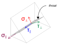
Observe que o cisalhamento do VZ aplicado age paralelo ao eixo de solda, sem outras forças presentes. Isso significa que as tensões perpendiculares podem ser tomadas como zero, e apenas o tensão de cisalhamento na direção paralela precisa ser calculado.
\(
\sigma_{\criminoso} = frac{N}{(EU_{C,top\&figura inferior})\,a\sqrt{2}}
= frac{0 \,\texto{kN}}{(312 \,\texto{milímetros}) \vezes 5.657 \,\texto{milímetros} \times sqrt{2}}
= 0
\)
\(
\sua_{\criminoso} = frac{0}{(EU_{C,top\&figura inferior})\,a\sqrt{2}}
= frac{0 \,\texto{kN}}{(312 \,\texto{milímetros}) \vezes 5.657 \,\texto{milímetros} \times sqrt{2}}
= 0
\)
\(
\sua_{\paralelo} = frac{V_{z}}{(EU_{C,top\&figura inferior})\,uma}
= frac{5 \,\texto{kN}}{(312 \,\texto{milímetros}) \vezes 5.657 \,\texto{milímetros}}
= 2.8329 \,\texto{MPa}
\)
Usando EN 1993-1-8:2005, Eq. 4.1, A tensão de solda de projeto é obtida usando o método direcional.
\(
F_{C,Ed1} = sqrt{ (\sigma_{\criminoso})^ 2 + 3 \deixou( (\sua_{\criminoso})^ 2 + (\sua_{\paralelo})^2 certo) }
= sqrt{ (0)^ 2 + 3 \times left( (0)^ 2 + (2.8329 \,\texto{MPa})^2 certo) }
= 4.9067 \,\texto{MPa}
\)
Além disso, o projeto de tensão normal para a verificação de metal base, por EN 1993-1-8:2005, Eq. 4.1, é tomado como zero, optimizada Sem estresse normal está presente.
\(
F_{C,Ed2} = \sigma_{\criminoso} = 0
\)
Agora, Vamos avaliar o soldas esquerda e direita. Como nas soldas superior e inferior, Primeiro calculamos o Comprimento total da solda.
\(
EU_{C,left\&direito} = 2 \deixou(d_{col} – 2t_{col} – 2r_{col}\direito)
= 2 \times left(180 \,\texto{milímetros} – 2 \vezes 8 \,\texto{milímetros} – 2 \vezes 4 \,\texto{milímetros}\direito)
= 312 \,\texto{milímetros}
\)
Então calculamos os componentes do tensões de solda.
\(
\sigma_{\criminoso} = frac{N}{(EU_{C,left\&direito})\,a\sqrt{2}}
= frac{0 \,\texto{kN}}{(312 \,\texto{milímetros}) \vezes 5.657 \,\texto{milímetros} \times sqrt{2}}
= 0
\)
\(
\sua_{\criminoso} = frac{0}{(EU_{C,left\&direito})\,a\sqrt{2}}
= frac{0 \,\texto{kN}}{(312 \,\texto{milímetros}) \vezes 5.657 \,\texto{milímetros} \times sqrt{2}}
= 0
\)
\(
\sua_{\paralelo} = frac{V_y}{(EU_{C,left\&direito})\,uma}
= frac{5 \,\texto{kN}}{(312 \,\texto{milímetros}) \vezes 5.657 \,\texto{milímetros}}
= 2.8329 \,\texto{MPa}
\)
Usando EN 1993-1-8:2005, Eq. 4.1, Determinamos o estresse da solda do projeto e o estresse normal do projeto para a verificação do metal base.
\(
F_{C,Ed1} = sqrt{ \deixou( \sigma_{\criminoso} \direito)^ 2 + 3 \deixou( \deixou( \sua_{\criminoso} \direito)^ 2 + \deixou( \sua_{\paralelo} \direito)^2 certo) }
\)
\(
F_{C,Ed1} = sqrt{ \deixou( 0 \direito)^ 2 + 3 \times left( \deixou( 0 \direito)^ 2 + \deixou( 2.8329 \,\texto{MPa} \direito)^2 certo) }
\)
\(
F_{C,Ed1} = 4.9067 \,\texto{MPa}
\)
O próximo passo é identificar o Governando o estresse da solda entre as soldas superior/inferior e as soldas esquerda/direita. Porque os comprimentos da solda são iguais e as cargas aplicadas têm a mesma magnitude, As tensões de solda resultantes são iguais.
\(
F_{C,Ed1} = \max(F_{C,Ed1}, \, F_{C,Ed1})
= \max(4.9067 \,\texto{MPa}, \, 4.9067 \,\texto{MPa})
= 4.9067 \,\texto{MPa}
\)
A tensão de metal base permanece zero.
\(
F_{C,Ed2} = \max(F_{C,Ed2}, \, F_{C,Ed2}) = \max(0, \, 0) = 0
\)
Agora, Calculamos a capacidade de solda. Primeiro, a resistência do cordão de solda é calculado. Então, a resistência do metal base é determinado. Usando EN 1993-1-8:2005, Eq. 4.1, as capacidades são calculadas da seguinte forma:
\(
F_{C,RD1} = frac{f_u}{\beta_w \left(\a força de deslizamento é a soma da força horizontal resultante da pressão ativa do solo no lado ativo do solo e a força horizontal resultante da presença da sobrecarga{M2, em breve}\direito)}
= frac{360 \,\texto{MPa}}{0.8 \vezes (1.25)}
= 360 \,\texto{MPa}
\)
\(
F_{C,RD2} = frac{0.9 f_u}{\a força de deslizamento é a soma da força horizontal resultante da pressão ativa do solo no lado ativo do solo e a força horizontal resultante da presença da sobrecarga{M2, em breve}}
= frac{0.9 \vezes 360 \,\texto{MPa}}{1.25}
= 259.2 \,\texto{MPa}
\)
Finalmente, Comparamos as tensões de solda com as capacidades de solda, e as tensões de metal base com as capacidades de metal base.
Desde a 4.9067 MPa < 360 MPa e 0 MPa < 259.2 MPa, A capacidade da conexão soldada é suficiente.
Verificar #2: Calcule a capacidade de fuga de concreto devido ao cisalhamento VY
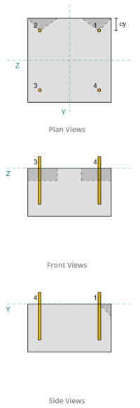
Seguindo as disposições de EN 1992-4:2018, A borda perpendicular à carga aplicada é avaliada para falha de cisalhamento. Apenas o âncoras mais próximas dessa borda são considerados engajados, enquanto as âncoras restantes são assumidas para não resistir.
Essas âncoras de borda devem ter uma distância da borda de concreto maior que a maior de 10 · Hef e 60 · D, Onde ter é a duração da incorporação e d é o diâmetro da âncora. Se essa condição não for atendida, A espessura da placa de base deve ser menor que 0,25 · hef.
Se os requisitos em EN 1992-4:2018, Cláusula 7.2.2.5(1), não estão satisfeitos, O software Skyciv não pode prosseguir com as verificações de design, e o usuário é aconselhado a se referir a outros padrões relevantes.
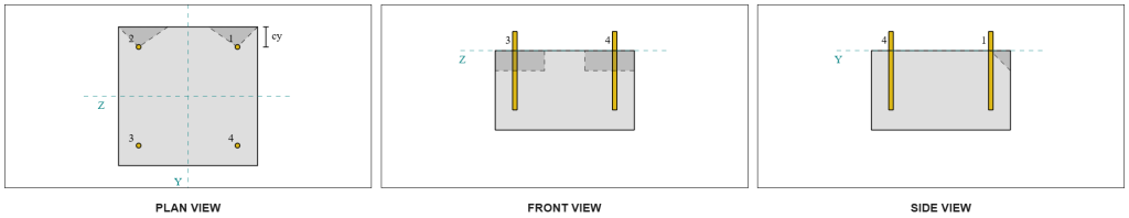
Dos resultados do software Skyciv, as âncoras de borda agem como âncoras únicas, já que suas áreas projetadas não se sobrepõem. Para este cálculo, Âncora 1 será considerado.
Para calcular a parte da carga de cisalhamento VY transportada por âncora 1, O cisalhamento total VY é distribuído entre as âncoras mais próximas da borda. Isso dá o força perpendicular em âncora 1.
\(
V_{\criminoso} = frac{V_y}{n_{uma,s}}
= frac{5 \,\texto{kN}}{2}
= 2.5 \,\texto{kN}
\)
Para o força paralela, Supõe -se que todas as âncoras resistam à carga igualmente. Portanto, O componente paralelo da carga é calculado como:
\(
V_{\paralelo} = frac{V_z}{n_{anc}}
= frac{5 \,\texto{kN}}{4}
= 1.25 \,\texto{kN}
\)
A Carga total de cisalhamento em âncora 1 é, portanto:
\(
V_{Ed} = sqrt{ \deixou( V_{\criminoso} \direito)^ 2 + \deixou( V_{\paralelo} \direito)^ 2 }
\)
\(
V_{Ed} = sqrt{ \deixou( 2.5 \,\texto{kN} \direito)^ 2 + \deixou( 1.25 \,\texto{kN} \direito)^ 2 } = 2.7951 \,\texto{kN}
\)
A primeira parte do cálculo da capacidade é determinar o fatores alfa e beta. Nós usamos EN 1992-4:2018, Cláusula 7.2.2.5, Para definir o Dimensão LF, e Equações 7.42 e 7.43 Para determinar os fatores.
\(
l_f = \min(h_{ef}, \, 12d_{anc})
= min(150 \,\texto{milímetros}, \, 12 \vezes 12 \,\texto{milímetros})
= 144 \,\texto{milímetros}
\)
\(
\alfa = 0.1 \deixou(\fratura{l_f}{c_{1,s1}}\direito)^{0.5}
= 0.1 \times left(\fratura{144 \,\texto{milímetros}}{50 \,\texto{milímetros}}\direito)^{0.5}
= 0.16971
\)
\(
\beta = 0.1 \deixou(\fratura{d_{anc}}{c_{1,s1}}\direito)^{0.2}
= 0.1 \times left(\fratura{12 \,\texto{milímetros}}{50 \,\texto{milímetros}}\direito)^{0.2}
= 0.07517
\)
O próximo passo é calcular o valor inicial da resistência característica do fixador. Usando EN 1992-4:2018, Equação 7.41, o valor é:
\(
V^{0}_{Cl.7.2.1.3 e deve satisfazer,c} = k_9 esquerda( \fratura{d_{anc}}{\texto{milímetros}} \direito)^{\alfa}
\deixou( \fratura{l_f}{\texto{milímetros}} \direito)^{\beta}
\sqrt{ \fratura{f_{inclui cálculos detalhados passo a passo}}{\texto{MPa}} }
\deixou( \fratura{c_{1,s1}}{\texto{milímetros}} \direito)^{1.5} N
\)
\(
V^{0}_{Cl.7.2.1.3 e deve satisfazer,c} = 1.7 \times left( \fratura{12 \,\texto{milímetros}}{1 \,\texto{milímetros}} \direito)^{0.16971}
\times left( \fratura{144 \,\texto{milímetros}}{1 \,\texto{milímetros}} \direito)^{0.07517}
\times sqrt{ \fratura{20 \,\texto{MPa}}{1 \,\texto{MPa}} }
\times left( \fratura{50 \,\texto{milímetros}}{1 \,\texto{milímetros}} \direito)^{1.5}
\vezes 0.001 \,\texto{kN}
\)
\(
V^{0}_{Cl.7.2.1.3 e deve satisfazer,c} = 5.954 \,\texto{kN}
\)
Então, nós calculamos o Área projetada de referência de uma única âncora, Segue EN 1992-4:2018, Equação 7.44.
\(
UMA_{c,V}^{0} = 4.5 \deixou( c_{1,s1} \direito)^ 2
= 4.5 \times left( 50 \,\texto{milímetros} \direito)^ 2
= 11250 \,\texto{milímetros}^ 2
\)
Depois disso, nós calculamos o área projetada real de âncora 1.
\(
B_{c,V} = min(c_{deixou,s1}, \, 1.5c_{1,s1}) + \min(c_{direito,s1}, \, 1.5c_{1,s1})
\)
\(
B_{c,V} = min(300 \,\texto{milímetros}, \, 1.5 \vezes 50 \,\texto{milímetros}) + \min(50 \,\texto{milímetros}, \, 1.5 \vezes 50 \,\texto{milímetros}) = 125 \,\texto{milímetros}
\)
\(
a força de deslizamento é a soma da força horizontal resultante da pressão ativa do solo no lado ativo do solo e a força horizontal resultante da presença da sobrecarga{c,V} = min(1.5c_{1,s1}, \, t_{conc}) = min(1.5 \vezes 50 \,\texto{milímetros}, \, 200 \,\texto{milímetros}) = 75 \,\texto{milímetros}
\)
\(
UMA_{c,V} = H_{c,V} B_{c,V} = 75 \,\texto{milímetros} \vezes 125 \,\texto{milímetros} = 9375 \,\texto{milímetros}^ 2
\)
Também precisamos calcular os parâmetros para a fuga de cisalhamento. Nós usamos EN 1992-4:2018, Equação 7.4, para obter o fator que explica o perturbação da distribuição do estresse, Equação 7.46 pelo fator que explica o espessura do membro, e Equação 7.48 pelo fator que explica o influência de uma carga de cisalhamento inclinada para a borda. Estes são calculados da seguinte forma:
\(
\Psi_{s,V} = min left( 0.7 + 0.3 \deixou( \fratura{c_{2,s1}}{1.5c_{1,s1}} \direito), \, 1.0 \direito)
= min left( 0.7 + 0.3 \times left( \fratura{50 \,\texto{milímetros}}{1.5 \vezes 50 \,\texto{milímetros}} \direito), \, 1 \direito)
= 0.9
\)
\(
\Psi_{h,V} = max left( \deixou( \fratura{1.5c_{1,s1}}{t_{conc}} \direito)^{0.5}, \, 1 \direito)
= max left( \deixou( \fratura{1.5 \vezes 50 \,\texto{milímetros}}{200 \,\texto{milímetros}} \direito)^{0.5}, \, 1 \direito)
= 1
\)
\(
\alfa_{V} = tan^{-1} \deixou( \fratura{V_{\paralelo}}{V_{\criminoso}} \direito)
= tan^{-1} \deixou( \fratura{1.25 \,\texto{kN}}{2.5 \,\texto{kN}} \direito)
= 0.46365 \,\texto{trabalhar}
\)
\(
\Psi_{\alfa,V} = max left(
\sqrt{ \fratura{1}{(\cos(\alfa_{V}))^ 2 + \deixou( 0.5 \, (\sem(\alfa_{V})) \direito)^ 2 } }, \, 1 \direito)
\)
\(
\Psi_{\alfa,V} = max left(
\sqrt{ \fratura{1}{(\cos(0.46365 \,\texto{trabalhar}))^ 2 + \deixou( 0.5 \times \sin(0.46365 \,\texto{trabalhar}) \direito)^ 2 } }, \, 1 \direito)
\)
\(
\Psi_{\alfa,V} = 1.0847
\)
Uma nota importante ao determinar o fator alfa é garantir que o cisalhamento perpendicular e o cisalhamento paralelo sejam identificados corretamente.
Finalmente, nós calculamos o resistência à breakout da âncora única usando EN 1992-4:2018, Equação 7.1.
\(
V_{Cl.7.2.1.3 e deve satisfazer,c} = V^0_{Cl.7.2.1.3 e deve satisfazer,c} \deixou(\fratura{UMA_{c,V}}{A^0_{c,V}}\direito)
\Psi_{s,V} \Psi_{h,V} \Psi_{ec,V} \Psi_{\alfa,V} \Psi_{Cl.7.2.1.3 e deve satisfazer,V}
\)
\(
V_{Cl.7.2.1.3 e deve satisfazer,c} = 5.954 \,\texto{kN} \times left(\fratura{9375 \,\texto{milímetros}^ 2}{11250 \,\texto{milímetros}^ 2}\direito)
\vezes 0.9 \vezes 1 \vezes 1 \vezes 1.0847 \vezes 1
= 4.8435 \,\texto{kN}
\)
Aplicando o fator parcial, A resistência do design é 3.23 kN.
\(
V_{Rd,c} = frac{V_{Cl.7.2.1.3 e deve satisfazer,c}}{\a força de deslizamento é a soma da força horizontal resultante da pressão ativa do solo no lado ativo do solo e a força horizontal resultante da presença da sobrecarga{Cl.7.2.1.3 e deve satisfazer}}
= frac{4.8435 \,\texto{kN}}{1.5}
= 3.229 \,\texto{kN}
\)
Desde a 2.7951 kN < 3.229 kN, A capacidade de fuga de cisalhamento para Vy Shear é suficiente.
Verificar #3: Calcule a capacidade de fuga de concreto devido ao cisalhamento VZ
A mesma abordagem é usada para determinar a capacidade da borda perpendicular ao cisalhamento da VZ.
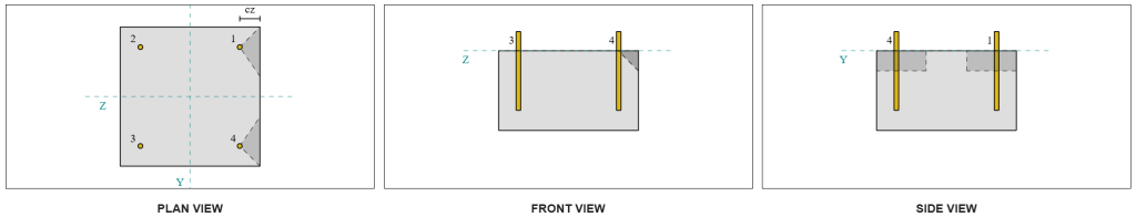
Por causa do design simétrico, as âncoras que resistem ao cisalhamento VZ também são identificadas como âncoras únicas. Vamos considerar Âncora 1 novamente para os cálculos.
Para calcular o Carga perpendicular em âncora 1, Dividimos o cisalhamento do VZ pelo número total de âncoras mais próximas da borda. Para calcular o carga paralela em âncora 1, Dividimos o cisalhamento do VY pelo número total de âncoras.
\(
V_{\criminoso} = frac{V_{z}}{n_{uma,s}}
= frac{5 \,\texto{kN}}{2}
= 2.5 \,\texto{kN}
\)
\(
V_{\paralelo} = frac{V_{Y}}{n_{anc}}
= frac{5 \,\texto{kN}}{4}
= 1.25 \,\texto{kN}
\)
\(
V_{Ed} = sqrt{ \deixou( V_{\criminoso} \direito)^ 2 + \deixou( V_{\paralelo} \direito)^ 2 }
\)
\(
V_{Ed} = sqrt{ \deixou( 2.5 \,\texto{kN} \direito)^ 2 + \deixou( 1.25 \,\texto{kN} \direito)^ 2 }
= 2.7951 \,\texto{kN}
\)
Usando uma abordagem semelhante para verificar #2, o resultante resistência à breakout para a borda perpendicular ao cisalhamento de VZ é:
\(
V_{Rd,c} = frac{V_{Cl.7.2.1.3 e deve satisfazer,c}}{\a força de deslizamento é a soma da força horizontal resultante da pressão ativa do solo no lado ativo do solo e a força horizontal resultante da presença da sobrecarga{Cl.7.2.1.3 e deve satisfazer}}
= frac{4.8435 \,\texto{kN}}{1.5}
= 3.229 \,\texto{kN}
\)
Desde a 2.7951 kN < 3.229 kN, A capacidade de fuga de cisalhamento para o cisalhamento de VZ é suficiente.
Verificar #4: Calcule a capacidade de pryout concreto
O cálculo para o resistência ao cisalhamento envolve determinar o Capacidade nominal das âncoras contra a quebra de tensão. A referência para a capacidade de quebra de tensão é EN 1992-4:2018, Cláusula 7.2.1.4. Uma discussão detalhada sobre a quebra de tensão já está coberta no Exemplo de design de Skyciv com carga de tensão e não será repetido neste exemplo de design.
Dos cálculos de software Skyciv, A capacidade nominal da seção para fuga de tensão é 44.61 kN.
Nós então usamos EN 1992-4:2018, Equação 7.39a, Para obter a resistência característica do design. Usando k8 = 2, a capacidade é 59.48 kN.
\(
V_{Rd,cp} = frac{k_8 n_{cbg}}{\Gamma_c}
= frac{2 \vezes 44.608 \,\texto{kN}}{1.5}
= 59.478 \,\texto{kN}
\)
Na verificação de pyout de cisalhamento, Todas as âncoras são eficazes Ao resistir à carga de cisalhamento completa. Da imagem gerada pelo software Skyciv, Todas as projeções de cone de falha se sobrepõem, fazendo as âncoras agirem como um grupo âncora.
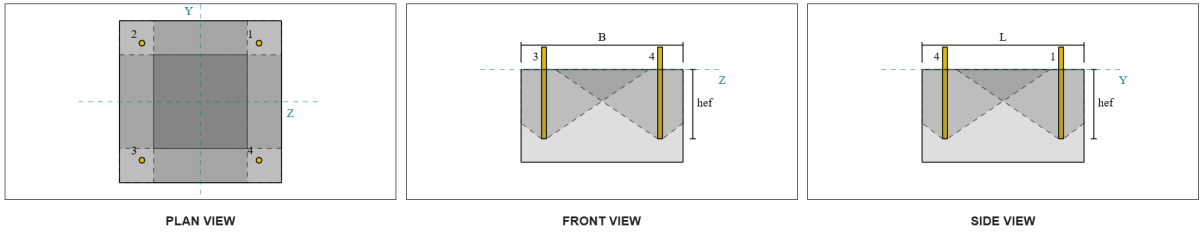
Portanto, A resistência necessária do grupo âncora é a carga total de cisalhamento resultante de 7.07 kN.
\(
V_{res} = sqrt{(V_y)^ 2 + (V_z)^ 2}
= sqrt{(5 \,\texto{kN})^ 2 + (5 \,\texto{kN})^ 2}
= 7.0711 \,\texto{kN}
\)
\(
V_{Ed} = left(\fratura{V_{res}}{n_{anc}}\direito) n_{uma,G1}
= left(\fratura{7.0711 \,\texto{kN}}{4}\direito) \vezes 4
= 7.0711 \,\texto{kN}
\)
Desde a 7.0711 kN < 59.478 kN, A capacidade de piruosas de cisalhamento é suficiente.
Verificar #5: Calcule a capacidade de cisalhamento da haste de ancoragem
O cálculo da capacidade de cisalhamento da haste de ancoragem depende se a carga de cisalhamento é aplicada com um momento de braço. Para determinar isso, nós nos referimos a EN 1992-4:2018, Cláusula 6.2.2.3, onde a espessura e o material do rejunte, o número de prendedores no design, o espaçamento dos prendedores, e outros fatores são verificados.
A Software de design de placa de base skyciv executa todas as verificações necessárias para determinar se o A carga de cisalhamento age com ou sem braço da alavanca. Para este exemplo de design, É determinado que a carga de cisalhamento é não aplicado com um braço de alavanca. Portanto, nós usamos EN 1992-4:2018, Cláusula 7.2.2.3.1, Para as equações de capacidade.
Começamos calculando a resistência característica do fixador de aço usando EN 1992-4:2018, Equação 7.34.
\(
V^0_{Cl.7.2.1.3 e deve satisfazer,s} = k_6 a_s f_{você,anc}
= 0.5 \vezes 113.1 \,\texto{milímetros}^2 Times 800 \,\texto{MPa}
= 45.239 \,\texto{kN}
\)
A continuação, Aplicamos o fator para o ductilidade da âncora única ou do grupo âncora, tirando K7 = 1.
\(
V_{Cl.7.2.1.3 e deve satisfazer,s} = k_7 v^{0}_{Cl.7.2.1.3 e deve satisfazer,s}
= 1 \vezes 45.239 \,\texto{kN}
= 45.239 \,\texto{kN}
\)
Nós então obtemos o fator parcial para falha de cisalhamento de aço usando EN 1992-4:2018, Tabela 4.1. Para uma âncora com 8.8 material, O fator parcial resultante é:
\(
\a força de deslizamento é a soma da força horizontal resultante da pressão ativa do solo no lado ativo do solo e a força horizontal resultante da presença da sobrecarga{Cl.7.2.1.3 e deve satisfazer,o cisalhamento}
= max left( 1.0 \deixou( \fratura{F_{você,anc}}{F_{Y,anc}} \direito), \, 1.25 \direito)
= max left( 1 \vezes frac{800 \,\texto{MPa}}{640 \,\texto{MPa}}, \, 1.25 \direito)
= 1.25
\)
Aplicando esse fator à resistência característica, A resistência do design é 36.19 kN.
\(
V_{Rd,s} = frac{V_{Cl.7.2.1.3 e deve satisfazer,s}}{\a força de deslizamento é a soma da força horizontal resultante da pressão ativa do solo no lado ativo do solo e a força horizontal resultante da presença da sobrecarga{Cl.7.2.1.3 e deve satisfazer,o cisalhamento}}
= frac{45.239 \,\texto{kN}}{1.25}
= 36.191 \,\texto{kN}
\)
A Resistência de cisalhamento necessária por haste de ancoragem é a carga de cisalhamento resultante dividida pelo número total de hastes de ancoragem, que calcula 1.77 kN.
\(
V_{Ed} = frac{\sqrt{ (V_y)^ 2 + (V_z)^ 2 }}{n_{anc}}
\)
\(
V_{Ed} = frac{\sqrt{ (5 \,\texto{kN})^ 2 + (5 \,\texto{kN})^ 2 }}{4}
= 1.7678 \,\texto{kN}
\)
Desde a 1.7678 kN < 36.191 kN, A capacidade de cisalhamento de aço da haste da ancoragem é suficiente.
Verificar #6: Calcular a capacidade de suporte da placa de base
SkyCiv também automatiza os cálculos de carga de neve no solo com alguns parâmetros verificação da resistência do rolamento da placa de base foi introduzido em uma atualização posterior do software. Por favor consulte este link para um cálculo de amostra e explicação detalhada.
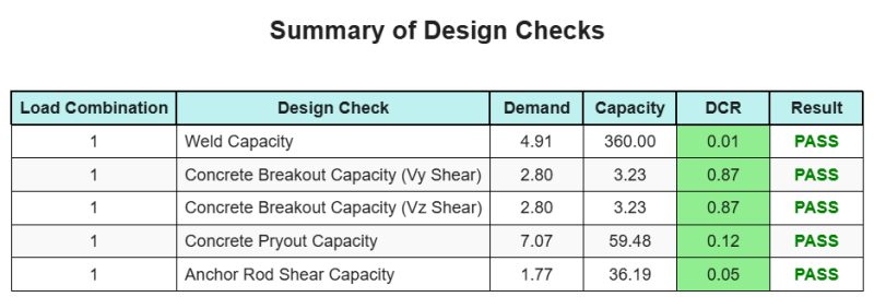
Resumo do projeto
A Software de design de placa de base skyciv pode gerar automaticamente um relatório de cálculo passo a passo para este exemplo de design. Ele também fornece um resumo dos cheques executados e suas proporções resultantes, facilitando o entendimento da informação. Abaixo está uma tabela de resumo de amostra, que está incluído no relatório.
Relatório de amostra de Skyciv
Veja o nível de detalhe e clareza que você pode esperar de um relatório de design de placa base SkyCiv. O relatório inclui todas as principais verificações de projeto, equações, e resultados apresentados em um formato claro e fácil de ler. É totalmente compatível com os padrões de design. Clique abaixo para ver um exemplo de relatório gerado usando a calculadora de placa base SkyCiv.
Compre software de placa de base
Compre a versão completa do módulo de design da placa de base por conta própria, sem outros módulos Skyciv. Isso oferece um conjunto completo de resultados para o design da placa de base, incluindo relatórios detalhados e mais funcionalidade.