Exemplo de design da placa de base usando EN 1993-1-8-2005, EN 1993-1-1-2005 e EN 1992-1-1-2004
Declaração de problemas
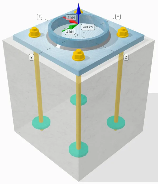
Determinar se a conexão de placa de coluna para base projetada é suficiente para um 50-carga de tensão kN, 4-carga de cisalhamento kN Vy, e 2-carga de cisalhamento kN Vz.
Dados dados
Coluna:
Seção de coluna: CHS193.7×10
Área da coluna: 5770.0 mm²
Material da coluna: S460
Placa Base:
Dimensões da placa de base: 300mm x 300 mm
Espessura da placa de base: 18milímetros
Material da placa de base: S235
Grout:
Espessura do rejunte: 0 milímetros
Concreto:
Dimensões concretas: 350mm x 350 mm
Espessura do concreto: 400 milímetros
Material concreto: C35/45
Rachado ou sem crack: Rachado
Âncoras:
Diâmetro da âncora: 16 milímetros
Comprimento eficaz de incorporação: 350 milímetros
Diâmetro da placa incorporada: 70 milímetros
Espessura da placa incorporada: 10 milímetros
Material de ancoragem: 4.8
Soldas:
Tipo de solda: Filé
Tamanho da solda: 7milímetros
Classificação de metal de enchimento: E42
Dados de âncora (a partir de Calculadora Skyciv):
Modelo na ferramenta gratuita SkyCiv
Modele o design da placa de base acima usando nossa ferramenta online gratuita hoje mesmo! Não é necessária inscrição.
Notas
O objetivo deste exemplo de projeto é demonstrar os cálculos passo a passo para verificações de capacidade envolvendo cisalhamento simultâneo e cargas axiais. Algumas das verificações necessárias já foram discutidas nos exemplos de design anteriores. Consulte os links fornecidos em cada seção.
Cálculos passo a passo
Verificar #1: Calcule a capacidade de solda
O completo carga de tração é resistido pelo seção inteira de solda, enquanto o componentes de carga de cisalhamento são distribuídos apenas para uma parte do comprimento total da solda. Esta parcela é determinada pela projeção de um 90° setor do centro da coluna até sua circunferência. Portanto, só metade da circunferência total é projetado para resistir à carga de cisalhamento.
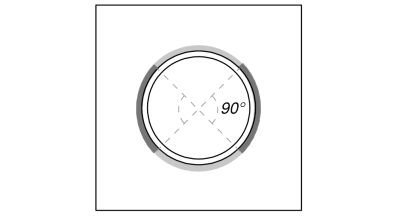
Primeiro calculamos o Comprimento total da solda quanto pelo parte da solda dentro da projeção de 90°.
\(EU_{soldar,completo} = pi d_{col} = pi vezes 193.7\ \texto{milímetros} = 608.53\ \texto{milímetros}\)
\(EU_{soldar} = frac{\pi d_{col}}{2} = frac{\PI Times 193.7\ \texto{milímetros}}{2} = 304.26\ \texto{milímetros}\)
A continuação, nós calculamos o carga de cisalhamento resultante.
\(V_r = \sqrt{(V_y)^ 2 + (V_z)^ 2} = sqrt{(4\ \texto{kN})^ 2 + (2\ \texto{kN})^ 2} = 4.4721\ \texto{kN}\)
Calculamos então o Força de rotação no membro e tensões de cisalhamento, levando em consideração a distribuição de carga assumida.
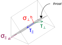
\( \sigma_{\criminoso} = frac{N_x}{EU_{soldar,completo}\,a\,\sqrt{2}} = frac{40\ \texto{kN}}{608.53\ \texto{milímetros} \vezes 4.95\ \texto{milímetros} \times sqrt{2}} = 9.39\ \texto{MPa} \)
\( \sua_{\criminoso} = frac{N_x}{EU_{soldar,completo}\,a\,\sqrt{2}} = frac{40\ \texto{kN}}{608.53\ \texto{milímetros} \vezes 4.95\ \texto{milímetros} \times sqrt{2}} = 9.39\ \texto{MPa} \)
\( \sua_{\paralelo} = frac{V_r}{EU_{soldar}\,uma} = frac{4.4721\ \texto{kN}}{304.26\ \texto{milímetros} \vezes 4.95\ \texto{milímetros}} = 2.9693\ \texto{MPa} \)
Depois disso, nós calculamos o tensões combinadas usando EN 1993-1-8:2005 Eq. (4.1).
\(F_{C,Ed1} = sqrt{(\sigma_{\criminoso})^ 2 + 3\grande((\sua_{\criminoso})^ 2 + (\sua_{\paralelo})^2\big)}\)
\(F_{C,Ed1} = sqrt{(9.39\ \texto{MPa})^ 2 + 3\grande((9.39\ \texto{MPa})^ 2 + (2.9693\ \texto{MPa})^2\big)}\)
\(F_{C,Ed1} = 19.471\ \texto{MPa}\)
Ao mesmo tempo, Nós determinamos o tensão no metal base usando a mesma equação.
\(F_{C,Ed2} = \sigma_{\criminoso} = 9.39\ \texto{MPa}\)
A continuação, nós calculamos o capacidade de soldagem. Primeiro determinamos o resistência à tração final (fu) do material mais fraco, e então use EN 1993-1-8:2005 Eq. (4.1) para obter o resistência de solda de filete e resistência de metais básicos.
\(f_u = \min\!\deixou(F_{você,\texto{col}},\ f_{você,\texto{pb}},\ f_{você,C}\direito) = \min\!\deixou(550\ \texto{MPa},\ 360\ \texto{MPa},\ 500\ \texto{MPa}\direito) = 360\ \texto{MPa}\)
\(F_{C,RD1} = frac{f_u}{\beta_w\,(\a força de deslizamento é a soma da força horizontal resultante da pressão ativa do solo no lado ativo do solo e a força horizontal resultante da presença da sobrecarga{M2,\text{soldar}})} = frac{360\ \texto{MPa}}{0.8 \vezes (1.25)} = 360\ \texto{MPa}\)
\(F_{C,RD2} = frac{0.9\,f_u}{\a força de deslizamento é a soma da força horizontal resultante da pressão ativa do solo no lado ativo do solo e a força horizontal resultante da presença da sobrecarga{M2,\text{soldar}}} = frac{0.9 \vezes 360\ \texto{MPa}}{1.25} = 259.2\ \texto{MPa}\)
Desde a 19.471 MPa < 360 MPa, A capacidade de solda é suficiente.
Verificar #2: Calcule a capacidade de rendimento flexural da placa de base devido à carga de tensão
Um exemplo de projeto para a capacidade de escoamento por flexão da placa de base já foi discutido no Exemplo de projeto de placa de base para tensão. Consulte este link para o cálculo passo a passo.
Verificar #3: Calcule a capacidade de fuga de concreto na tensão
Um exemplo de projeto para a capacidade de ruptura do concreto devido à carga de tração já foi discutido no Exemplo de projeto de placa de base para tração. Consulte este link para o cálculo passo a passo.
Verificar #4: Calcule a capacidade de extração de âncora
Um exemplo de projeto para a capacidade de arrancamento da ancoragem já foi discutido no Exemplo de projeto de placa base para tração. Consulte este link para o cálculo passo a passo.
Verificar #5: Calcule a capacidade de explosão lateral na direção y
Um exemplo de projeto para a capacidade de explosão da face lateral na direção Y já foi discutido no Exemplo de projeto de placa base para tensão. Consulte este link para o cálculo passo a passo.
Verificar #6: Calcule a capacidade de explosão lateral na direção z
Um exemplo de projeto para a capacidade de explosão da face lateral na direção Z já foi discutido no Exemplo de projeto de placa base para tensão. Consulte este link para o cálculo passo a passo.
Verificar #7: Calcule a capacidade de suporte da placa de base nos furos de ancoragem (Vy cisalhamento)
Um exemplo de projeto para a capacidade de suporte da placa de base nos furos de ancoragem para cisalhamento Vy já foi discutido no Exemplo de projeto de placa de base para compressão e cisalhamento. Consulte este link para o cálculo passo a passo.
Verificar #8: Calcule a capacidade de suporte da placa de base nos furos de ancoragem (Vz cisalhamento)
Um exemplo de projeto para a capacidade de suporte da placa de base nos furos de ancoragem para cisalhamento Vz já foi discutido no Exemplo de projeto de placa de base para compressão e cisalhamento. Consulte este link para o cálculo passo a passo.
Verificar #9: Calcular a capacidade de ruptura do concreto (Vy cisalhamento)
Um exemplo de projeto para a capacidade do concreto em ruptura devido ao cisalhamento Vy já foi discutido no Exemplo de projeto de placa base para cisalhamento. Consulte este link para o cálculo passo a passo.
Verificar #10: Calcular a capacidade de ruptura do concreto (Vz cisalhamento)
Um exemplo de projeto para a capacidade do concreto em ruptura devido ao cisalhamento Vz já foi discutido no Exemplo de projeto de placa de base para cisalhamento. Consulte este link para o cálculo passo a passo.
Verificar #11: Calcular a capacidade de saída
Um exemplo de projeto para a capacidade de arrancamento do concreto já foi discutido no Exemplo de projeto de placa base para cisalhamento. Consulte este link para o cálculo passo a passo.
Verificar #12: Calcule a capacidade de cisalhamento da haste de ancoragem
O efeito do carga de tensão na capacidade da haste de ancoragem é considerada nesta verificação se o a força de cisalhamento atua com um braço de alavanca. Contudo, neste exemplo, o cisalhamento atua sem braço de alavanca. Portanto, a interação entre tensões de cisalhamento e tração na haste de ancoragem será avaliada separadamente no verificação de interação.
Para o cálculo passo a passo da capacidade de corte sem braço de alavanca, por favor consulte este link.
O software SkyCiv Base Plate Design pode realizar todas as verificações necessárias para determinar se a carga de cisalhamento atua com ou sem braço de alavanca. Você pode experimente a ferramenta gratuita hoje.
Verificar #13: Calcular a verificação da interação do aço da âncora
Nós usamos EN 1992-4:2018 Tabela 7.3 Eq. (7.54) para avaliar o interação entre as tensões de cisalhamento e tração na haste de ancoragem. Substituindo a tensão de tração e a capacidade, bem como a tensão de cisalhamento e a capacidade na equação, o resultante valor de interação é:
\(I_{interno} = left(\fratura{N_{Ed}}{N_{Rd,s}}\direito)^ 2 + \deixou(\fratura{V_{Ed}}{V_{Rd,s}}\direito)^2)
\(I_{interno} = left(\fratura{10\ \texto{kN}}{49.22\ \texto{kN}}\direito)^ 2 + \deixou(\fratura{1.118\ \texto{kN}}{38.604\ \texto{kN}}\direito)A partir da elevação do solo gerada a partir das elevações do Google 0.042117\)
Desde a 0.042 < 1.0, a verificação da interação de falha de aço da haste de ancoragem é suficiente.
Verificar #14: Calcular a verificação de interação de falha de concreto
SkyCiv também automatiza os cálculos de carga de neve no solo com alguns parâmetros verificação de interação é necessário para falhas concretas sob carga simultânea de cisalhamento e tração. Por esta, nós usamos EN 1992-4:2018 Tabela 7.3 Eq. (7.55) e Eq. (7.56).
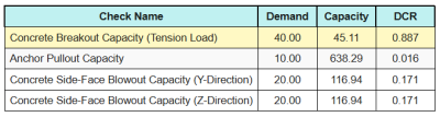
Aqui estão as proporções resultantes para todos verificações de tração.
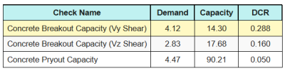
Aqui estão as proporções resultantes para todos verificações de cisalhamento.
Primeiro, nós verificamos usando Eq. (7.55) e compare o resultado com o limite máximo de interação de 1.0.
\(I_{\texto{caso1}} = left(\deixou(\fratura{N_{Ed}}{N_{Rd}}\direito)^{1.5}\direito) + \deixou(\deixou(\fratura{V_{Ed}}{V_{Rd}}\direito)^{1.5}\direito)\)
\(I_{\texto{caso1}} = left(\deixou(\fratura{40}{45.106}\direito)^{1.5}\direito) + \deixou(\deixou(\fratura{4.1231}{14.296}\direito)^{1.5}\direito) = 0.99\)
A continuação, nós verificamos usando Eq. (7.56) e compare o resultado com o limite máximo de interação de 1.2.
\(I_{\texto{case2}} = frac{N_{Ed}}{N_{Rd}} + \fratura{V_{Ed}}{V_{Rd}} = frac{40}{45.106} + \fratura{4.1231}{14.296} = 1.1752\)
Desde a 0.99 < 1.0 e 1.175 < 1.2, a verificação de interação de falha de concreto é suficiente.
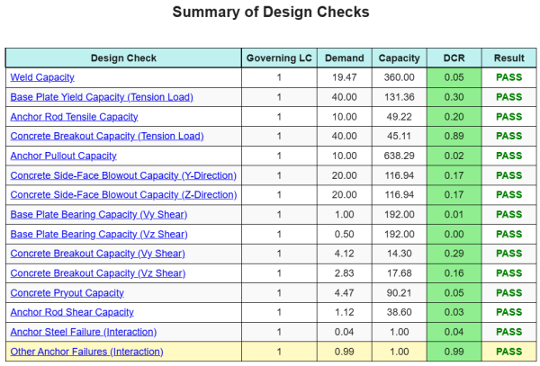
Resumo do projeto
A Software de design de placa de base skyciv pode gerar automaticamente um relatório de cálculo passo a passo para este exemplo de design. Ele também fornece um resumo dos cheques executados e suas proporções resultantes, facilitando o entendimento da informação. Abaixo está uma tabela de resumo de amostra, que está incluído no relatório.
Relatório de amostra de Skyciv
Veja o nível de detalhe e clareza que você pode esperar de um relatório de design de placa base SkyCiv. O relatório inclui todas as principais verificações de projeto, equações, e resultados apresentados em um formato claro e fácil de ler. É totalmente compatível com os padrões de design. Clique abaixo para ver um exemplo de relatório gerado usando a calculadora de placa base SkyCiv.
(Relatório de amostra a ser adicionado em breve)
Compre software de placa de base
Compre a versão completa do módulo de design da placa de base por conta própria, sem outros módulos Skyciv. Isso oferece um conjunto completo de resultados para o design da placa de base, incluindo relatórios detalhados e mais funcionalidade.