Exemplo de design da placa de base usando AISC 360-22 e ACI 318-19
Declaração de problemas
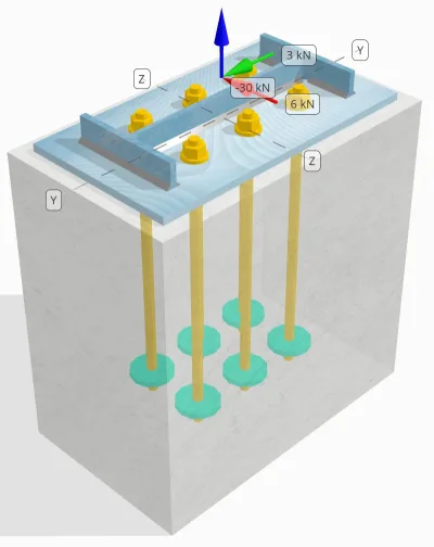
Determine se a conexão projetada da coluna à placa de base é suficiente para 30 carga de tensão kN, 3 carga de cisalhamento kN Vy, e 6 carga de cisalhamento kN Vz.
Dados dados
Coluna:
Seção de coluna: W14x30
Área da coluna: 5709.7 milímetros2
Material da coluna: A992
Placa Base:
Dimensões da placa de base: 250 mm x 250 milímetros
Espessura da placa de base: 12 milímetros
Material da placa de base: A992
Grout:
Espessura do rejunte: 0 milímetros
Concreto:
Dimensões concretas: 300 mm x 500 milímetros
Espessura do concreto: 500 milímetros
Material concreto: 20.7 MPa
Rachado ou sem crack: Rachado
Âncoras:
Diâmetro da âncora: 16 milímetros
Comprimento eficaz de incorporação: 400 milímetros
Final de âncora: Placa Circular
Diâmetro da placa incorporada: 70 milímetros
Espessura da placa incorporada: 10 milímetros
Material de aço: F1554 Gr.55
Roscas no plano de cisalhamento: Incluído
Soldas:
Tamanho da solda: 7 milímetros
Classificação de metal de enchimento: E70XX
Dados de âncora (a partir de Calculadora Skyciv):
Modelo na ferramenta gratuita SkyCiv
Modele o design da placa de base acima usando nossa ferramenta online gratuita hoje mesmo! Não é necessária inscrição.
Observação
O objetivo deste exemplo de projeto é demonstrar os cálculos passo a passo para verificações de capacidade envolvendo cisalhamento simultâneo e cargas axiais. Algumas das verificações necessárias já foram discutidas nos exemplos de design anteriores. Consulte os links fornecidos em cada seção.
Cálculos passo a passo
Verificar #1: Calcule a capacidade de solda
Para determinar a capacidade de soldagem sob carregamento simultâneo, primeiro precisamos calcular a demanda de solda devido ao carga de cisalhamento e a demanda de solda devido ao carga de tensão. Você pode consultar isso link para o procedimento para obter as demandas de solda para cisalhamento, e isso link para as demandas de solda por tensão.
Para este projeto, a demanda de solda na web devido à carga de tensão é encontrado como segue, onde a tensão é expressa como força por unidade de comprimento.
\(r_{você,\texto{rede}} = frac{T_{você,\texto{âncora}}}{eu_{\texto{ef}}} = frac{5\ \texto{kN}}{93.142\ \texto{milímetros}} = 0.053681\ \texto{kN / mm}\)
além disso, a tensão de soldagem em qualquer parte da seção do pilar devido à carga de cisalhamento é determinado como:
\(v_{uy} = frac{V_y}{EU_{\texto{soldar}}} = frac{3\ \texto{kN}}{1250.7\ \texto{milímetros}} = 0.0023987\ \texto{kN / mm}\)
\(v_{para} = frac{V_z}{EU_{\texto{soldar}}} = frac{6\ \texto{kN}}{1250.7\ \texto{milímetros}} = 0.0047973\ \texto{kN / mm}\)
Como existe uma combinação de cargas de tração e cisalhamento no rede, precisamos obter a resultante. Expressando isso como força por unidade de comprimento, temos:
\(r_u = sqrt{(r_{você,\texto{rede}})^ 2 + (v_{uy})^ 2 + (v_{para})^ 2}\)
\(r_u = sqrt{(0.053681\ \texto{kN / mm})^ 2 + (0.0023987\ \texto{kN / mm})^ 2 + (0.0047973\ \texto{kN / mm})^ 2}\)
\(r_u = 0.053949\ \texto{kN / mm}\)
Para o flanges, apenas tensões de cisalhamento estão presentes. Por isso, a resultante é:
\(r_u = sqrt{(v_{uy})^ 2 + (v_{para})^ 2}\)
\(r_u = sqrt{(0.0023987\ \texto{kN / mm})^ 2 + (0.0047973\ \texto{kN / mm})^ 2} = 0.0053636\ \texto{kN / mm}\)
A continuação, nós calculamos o capacidades de soldagem. Para a flange, nós determinamos o ângulo θ usando o Vz e Vy cargas.
\( \teta = tan^{-1}\!\deixou(\fratura{v_{uy}}{v_{para}}\direito) = tan^{-1}\!\deixou(\fratura{0.0023987\ \texto{kN / mm}}{0.0047973\ \texto{kN / mm}}\direito) = 0.46365\ \texto{trabalhar} \)
Consequentemente, a kds fator e capacidade de soldagem são calculados usando AISC 360-22 Eq. J2-5 e Eq. J2-4.
\(inclui cálculos detalhados passo a passo{ds} = 1.0 + 0.5(\sem(\theta))^{1.5} = 1 + 0.5 \vezes (\sem(0.46365\ \texto{trabalhar}))^{1.5} = 1.1495\)
\(\phi r_{n,flg} = phi,0,6,F_{Exx}\,E_w,k_{ds} = 0.75 \vezes 0.6 \vezes 480\ \texto{MPa} \vezes 4.95\ \texto{milímetros} \vezes 1.1495 = 1.2291\ \texto{kN / mm}\)
Para a web, calculamos o ângulo θ usando uma fórmula diferente. Observe que Uau é usado na fórmula, pois representa a carga paralela ao eixo de solda.
\( \teta = cos^{-1}\!\deixou(\fratura{v_{uy}}{r_u}\direito) = cos^{-1}\!\deixou(\fratura{0.0023987\ \texto{kN / mm}}{0.053949\ \texto{kN / mm}}\direito) = 1.5263\ \texto{trabalhar} \)
Usando AISC 360-22 Eq. J2-5 e Eq. J2-4, a kds fator e a capacidade de soldagem resultante são determinados da mesma maneira.
\(inclui cálculos detalhados passo a passo{ds} = 1.0 + 0.5(\sem(\theta))^{1.5} = 1 + 0.5 \vezes (\sem(1.5263\ \texto{trabalhar}))^{1.5} = 1.4993\)
\(\phi r_{n,rede} = phi,0,6,F_{Exx}\,E_w,k_{ds} = 0.75 \vezes 0.6 \vezes 480\ \texto{MPa} \vezes 4.95\ \texto{milímetros} \vezes 1.4993 = 1.603\ \texto{kN / mm}\)
por último, nós atuamos verificações de metais básicos tanto para a coluna quanto para a placa de base, então obtenha a capacidade governante do metal base.
\( \phi r_{nbm,col} = phi,0,6,F_{você,col}\,t_{col,metade} = 0.75 \vezes 0.6 \vezes 448.2\ \texto{MPa} \vezes 3.429\ \texto{milímetros} = 0.6916\ \texto{kN / mm} \)
\( \phi r_{nbm,pb} = phi,0,6,F_{você,pb}\,t_{pb} = 0.75 \vezes 0.6 \vezes 400\ \texto{MPa} \vezes 12\ \texto{milímetros} = 2.1595\ \texto{kN / mm} \)
\( \phi r_{nbm} = mingrande(\phi r_{nbm,pb},\ \phi r_{nbm,col}\grande) = min(2.1595\ \texto{kN / mm},\ 0.6916\ \texto{kN / mm}) = 0.6916\ \texto{kN / mm} \)
Comparamos então o capacidades de solda de filete e capacidades de metais básicos para as demandas de soldagem no flanges e web separadamente.
Desde a 0.053949 kN / mm < 0.6916 kN / mm, A capacidade de solda é suficiente.
Verificar #2: Calcule a capacidade de rendimento flexural da placa de base devido à carga de tensão
Um exemplo de projeto para a capacidade de escoamento por flexão da placa de base já foi discutido no Exemplo de projeto de placa de base para tensão. Consulte este link para o cálculo passo a passo.
Verificar #3: Calcule a capacidade de tração à haste de ancoragem
Um exemplo de projeto para a capacidade de tração da haste de ancoragem já foi discutido no Exemplo de projeto de placa de base para tração. Consulte este link para o cálculo passo a passo. Consulte este link para o cálculo passo a passo.
Verificar #4: Calcule a capacidade de fuga de concreto na tensão
Um exemplo de projeto para a capacidade do concreto em ruptura por tração já foi discutido no Exemplo de projeto de placa de base para tração. Consulte este link para o cálculo passo a passo. Consulte este link para o cálculo passo a passo.
Verificar #5: Calcule a capacidade de extração de âncora
Um exemplo de projeto para a capacidade de extração da âncora já foi discutido no Exemplo de projeto de placa de base para tração. Consulte este link para o cálculo passo a passo. Consulte este link para o cálculo passo a passo.
Verificar #6: Calcule a capacidade de flexão da placa incorporada
Um exemplo de projeto para a verificação suplementar da capacidade de escoamento por flexão da placa embutida já foi discutido no Exemplo de projeto de placa base para tração. Consulte este link para o cálculo passo a passo.
Verificar #7: Calcule a capacidade de explosão lateral na direção y
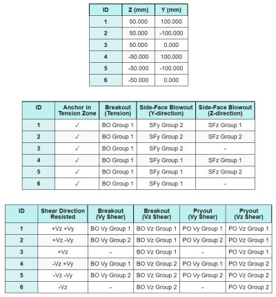
Para calcular o Explosão lateral (SFBO) Um guia para combinações de carga Eurocode, primeiro determinamos o total força de tensão nas âncoras mais próximas da borda. Para esta verificação, avaliaremos a capacidade da aresta ao longo do Direção Y.
Uma vez que as projeções do cone de falha do SFBO ao longo da direção Y se sobrepõem, as âncoras são tratadas como um grupo âncora.
A demanda total de tensão do grupo de ancoragem é calculada como:
\(N_{fazer} = left(\fratura{N_x}{n_{uma,t}}\direito) n_{Y,G1} = left(\fratura{30\ \texto{kN}}{6}\direito) \vezes 3 = 15\ \texto{kN}\)
A continuação, Nós determinamos o distâncias de borda:
\(c_{z,\min} = min(c_{\texto{deixou},G1},\ c_{\texto{direito},G1}) = min(100\ \texto{milímetros},\ 200\ \texto{milímetros}) = 100\ \texto{milímetros}\)
\(c_{Y,\min} = min(c_{\texto{figura superior},G1},\ c_{\texto{figura inferior},G1}) = min(150\ \texto{milímetros},\ 150\ \texto{milímetros}) = 150\ \texto{milímetros}\)
Usando essas distâncias de borda, nós calculamos o capacidade do grupo âncora conforme ACI 318-19 Eq. (17.6.4.1).
\(N_{como} = left(\fratura{1 + \dfrac{c_{Y,\min}}{c_{z,\min}}}{4} + \fratura{S_{soma,Y,G1}}{6\,c_{z,\min}}\direito)\vezes 13 \times left(\fratura{c_{z,\min}}{1\ \texto{milímetros}}\direito)\times sqrt{\fratura{UMA_{brg}}{\texto{milímetros}^ 2}}\ \lambda_a sqrt{\fratura{f_c}{\texto{MPa}}}\vezes 0.001\ \texto{kN}\)
\(N_{como} = left(\fratura{1 + \dfrac{150\ \texto{milímetros}}{100\ \texto{milímetros}}}{4} + \fratura{200\ \texto{milímetros}}{6\vezes 100\ \texto{milímetros}}\direito)\vezes 13 \times left(\fratura{100\ \texto{milímetros}}{1\ \texto{milímetros}}\direito)\times sqrt{\fratura{3647.4\ \texto{milímetros}^ 2}{1\ \texto{milímetros}^ 2}}\vezes 1 \times sqrt{\fratura{20.68\ \texto{MPa}}{1\ \texto{MPa}}}\vezes 0.001\ \texto{kN}\)
\(N_{como} = 342.16\ \texto{kN}\)
Na equação original, um fator de redução é aplicado quando o espaçamento da âncora é menor que 6ca₁, assumindo que as âncoras com cabeça têm distância de borda suficiente. Contudo, neste exemplo de design, optimizada ca₂ < 3ca₁, a calculadora SkyCiv aplica um fator de redução adicional para contabilizar a capacidade de borda reduzida.
Finalmente, a projetar capacidade SFBO é:
\(\phi N_{como} = phi,N_{como} = 0.7 \vezes 342.16\ \texto{kN} = 239.51\ \texto{kN}\)
Desde a 15 kN < 239.51 kN, a capacidade SFBO ao longo da direção Y é suficiente.
Verificar #8: Calcule a capacidade de explosão lateral na direção z
Seguindo a mesma abordagem que em Verificar #7, a demanda total de tensão do grupo de âncoras para as âncoras mais próximas do Direção Z borda é:
\(N_{fazer} = left(\fratura{N_x}{n_{uma,t}}\direito)n_{z,G1} = left(\fratura{30\ \texto{kN}}{6}\direito)\vezes 2 = 10\ \texto{kN}\)
A distâncias de borda são calculados como:
\(c_{Y,\min} = min(c_{\texto{figura superior},G1},\ c_{\texto{figura inferior},G1}) = min(150\ \texto{milímetros},\ 350\ \texto{milímetros}) = 150\ \texto{milímetros}\)
\(c_{z,\min} = min(c_{\texto{deixou},G1},\ c_{\texto{direito},G1}) = min(100\ \texto{milímetros},\ 100\ \texto{milímetros}) = 100\ \texto{milímetros}\)
A capacidade nominal de SFBO é então determinado como:
\(N_{como} = left(\fratura{1 + \dfrac{c_{z,\min}}{c_{Y,\min}}}{4} + \fratura{S_{soma,z,G1}}{6\,c_{Y,\min}}\direito)\vezes 13 \times left(\fratura{c_{Y,\min}}{1\ \texto{milímetros}}\direito)\times sqrt{\fratura{UMA_{brg}}{\texto{milímetros}^ 2}}\ \lambda_a sqrt{\fratura{f_c}{\texto{MPa}}}\vezes 0.001\ \texto{kN}\)
\(N_{como} = left(\fratura{1 + \dfrac{100\ \texto{milímetros}}{150\ \texto{milímetros}}}{4} + \fratura{100\ \texto{milímetros}}{6\vezes 150\ \texto{milímetros}}\direito)\vezes 13 \times left(\fratura{150\ \texto{milímetros}}{1\ \texto{milímetros}}\direito)\times sqrt{\fratura{3647.4\ \texto{milímetros}^ 2}{1\ \texto{milímetros}^ 2}}\vezes 1 \times sqrt{\fratura{20.68\ \texto{MPa}}{1\ \texto{MPa}}}\vezes 0.001\ \texto{kN}\)
\(N_{como} = 282.65\ \texto{kN}\)
Como a distância da borda ca₂ ainda é menor que 3ca₁, o mesmo fator de redução modificado é aplicado.
Finalmente, a projetar capacidade SFBO é:
\(\phi N_{como} = phi,N_{como} = 0.7 \vezes 282.65\ \texto{kN} = 197.86\ \texto{kN}\)
Desde a 10 kN < 197.86 kN, a capacidade do SFBO ao longo do Direção Z é suficiente.
Verificar #9: Calcular a capacidade de breakout (Vy cisalhamento)
Um exemplo de projeto para a capacidade de ruptura do concreto em cisalhamento Vy já foi discutido no Exemplo de projeto de placa base para cisalhamento. Consulte este link para o cálculo passo a passo.
Verificar #10: Calcular a capacidade de breakout (Vz cisalhamento)
Um exemplo de projeto para a capacidade de ruptura do concreto em cisalhamento Vy já foi discutido no Exemplo de projeto de placa base para cisalhamento. Consulte este link para o cálculo passo a passo.
Verificar #11: Calcular a capacidade de saída (Vy cisalhamento)
Um exemplo de projeto para a capacidade do concreto contra ruptura de arrancamento devido ao cisalhamento Vy já foi discutido no Exemplo de projeto de placa de base para cisalhamento. Consulte este link para o cálculo passo a passo.
Verificar #12: Calcular a capacidade de saída (Vz cisalhamento)
Um exemplo de projeto para a capacidade do concreto contra ruptura de arrancamento devido ao cisalhamento Vy já foi discutido no Exemplo de projeto de placa de base para cisalhamento. Consulte este link para o cálculo passo a passo.
Verificar #13: Calcule a capacidade de cisalhamento da haste de ancoragem
Um exemplo de projeto para a capacidade de cisalhamento da haste de ancoragem já foi discutido no Exemplo de projeto de placa de base para cisalhamento. Consulte este link para o cálculo passo a passo.
Verificar #14: Calcular o cisalhamento da haste de ancoragem e a capacidade axial (AISC)
Para determinar a capacidade da haste de ancoragem sob cargas axiais e de cisalhamento combinadas, nós usamos AISC 360-22 Eq. J3-3a. Nesta calculadora, a equação é reorganizada para expressar o resultado como a resistência ao cisalhamento modificada.
A demanda de cisalhamento é definido como o carga de cisalhamento por âncora.
\(V_{fazer} =V_{fazer} = 2.5\ \texto{kN}\)
A demanda de tensão é expresso como o tensão de tração na haste de ancoragem.
\(f_{fora} = frac{N_{fazer}}{UMA_{haste}} = frac{5\ \texto{kN}}{201.06\ \texto{milímetros}^ 2} = 24.868\ \texto{MPa}\)
A capacidade de cisalhamento modificada da haste de ancoragem é então calculado como:
\(F'_{novo} = \min\!\deixou(1.3\,F_{novo} – \deixou(\fratura{F_{novo}}{\Phi f_{não}}\direito) f_{fora},\; F_{novo}\direito)\)
\(F'_{novo} = \min\!\deixou(1.3\vezes 232.69\ \texto{MPa} – \deixou(\fratura{232.69\ \texto{MPa}}{0.75\vezes 387.82\ \texto{MPa}}\direito)\vezes 24.868\ \texto{MPa},\; 232.69\ \texto{MPa}\direito) = 232.69\ \texto{MPa}\)
Multiplicamos então esta força pelo área de âncora usando AISC 360-22 Eq. J3-2.
\(\phi R_{n,\texto{aisc}} = Phi f'_{novo} UMA_{\texto{haste}} = 0.75 \vezes 232.69\ \texto{MPa} \vezes 201.06\ \texto{milímetros}A partir da elevação do solo gerada a partir das elevações do Google 35.09\ \texto{kN}\)
Desde a 2.5 kN < 35.09 kN, a capacidade da haste de ancoragem é suficiente.
Verificar #15: Calcular verificações de interação (ACI)
Ao verificar a capacidade da haste de ancoragem sob cargas combinadas de cisalhamento e tensão usando ACI, uma abordagem diferente é aplicada. Para completar, também realizamos o Verificações de interação ACI neste cálculo, que incluem outros verificações de interação concreta também.
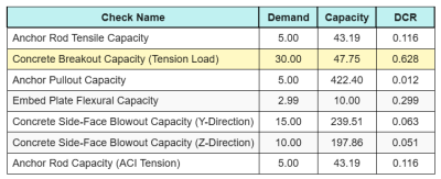
Aqui estão os resultados proporções para todas as verificações de tensão ACI:
E aqui estão os resultados proporções para todas as verificações de cisalhamento ACI:
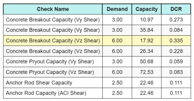
Obtemos o cheque com a maior proporção e comparamos com a taxa de interação máxima usando ACI 318-19 Eq. 17.8.3.
\(I_{interno} = frac{N_{fazer}}{\phi N_n} + \fratura{V_{fazer}}{\phi V_n} = frac{30}{47.749} + \fratura{6}{17.921} = 0.96308\)
Desde a 0.96 < 1.2, a verificação de interação é suficiente.
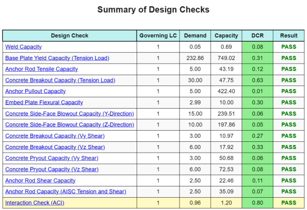
Resumo do projeto
A Software de design de placa de base skyciv pode gerar automaticamente um relatório de cálculo passo a passo para este exemplo de design. Ele também fornece um resumo dos cheques executados e suas proporções resultantes, facilitando o entendimento da informação. Abaixo está uma tabela de resumo de amostra, que está incluído no relatório.
Relatório de amostra de Skyciv
Veja o nível de detalhe e clareza que você pode esperar de um relatório de design de placa base SkyCiv. O relatório inclui todas as principais verificações de projeto, equações, e resultados apresentados em um formato claro e fácil de ler. É totalmente compatível com os padrões de design. Clique abaixo para ver um exemplo de relatório gerado usando a calculadora de placa base SkyCiv.
Compre software de placa de base
Compre a versão completa do módulo de design da placa de base por conta própria, sem outros módulos Skyciv. Isso oferece um conjunto completo de resultados para o design da placa de base, incluindo relatórios detalhados e mais funcionalidade.