A guide on the Direct Strength Method for Cold Formed Steel
Cold-formed steel member design is challenging due to the complex stability behavior of the thin-walled members. Per affrontare questo problema sono stati sviluppati diversi metodi, come il metodo della forza diretta (DSM), l’approccio più flessibile e moderno. SkyCiv is committed to help supporting DSM, through resources such as this and software that supports cold formed steel design through this approach.
Il DSM fornisce previsioni sulla resistenza degli elementi formati a freddo senza calcolare le larghezze effettive [1] (Il calcolo delle larghezze effettive è spesso un processo complesso con molte limitazioni per analizzare forme geometriche complesse). In questo metodo, the calculation of critical buckling strength can be carried out in various approaches, principalmente il metodo delle strisce finite (FSM) e il metodo degli elementi finiti (CINQUE). In questa guida, esploreremo:
- Cos'è il metodo della forza diretta
- Acceptance and Adoption in the Industry
- Metodo convenzionale delle strisce finite
- Buckling Mode Types
- What are the DSM Factors?
- Metodo della striscia finita nel generatore di sezioni SkyCiv
Cos'è il metodo della forza diretta (DSM)
La Metodo della forza diretta (DSM) is a design approach used predominately for the analysis and design of cold-formed steel members. Unlike traditional methods (such as the Effective Width Method) that rely on calculating effective section properties to account for local buckling, the DSM directly computes the member’s strength using its full, unreduced cross-sectional properties.
Pros and Cons of Direct Strength Method
| Professionisti | Contro |
|---|---|
| Simplifies Design Process: Reduces complexity by eliminating effective width calculations. | Learning Curve: Requires engineers to become familiar with new concepts and formulations. |
| Enhanced Accuracy: Directly accounts for various buckling modes for precise strength predictions. | Limited Historical Data: Less empirical data available for some specific applications compared to traditional methods. |
| Versatile Application: Suitable for complex and unconventional cross-sections. | Software Dependence: May require advanced software tools not readily available to all practitioners. |
| Unified Methodology: Provides a consistent approach across different buckling behaviors. | Standard Compliance: Not all regional codes may fully incorporate DSM provisions yet. |
| Facilitates Innovation: Encourages the use of new materials and shapes due to its adaptable framework. | Resistance to Change: Industry inertia can slow adoption as practitioners stick to familiar methods. |
Adoption and Acceptance:
The DSM is recognized and incorporated into major international design standards, tra cui:
- AISI S100: Specifiche nordamericane per la progettazione di elementi strutturali in acciaio formati a freddo.
- AS / NZS 4600: Australian/New Zealand Standard for Cold-Formed Steel Structures.
DSM is also being prioritised as a future method by being taught in universities and becoming a more common method taught in cold formed design courses. We’re also seeing an increase in it’s support by structural analysis and design software packages who are integrating DSM into their design modules.
Tuttavia, there are still some obstacles and challenges in the DSM being widely-adopted, since it is a relatively new/untaught method. Transitioning from traditional methods requires training and adaptation, which some practitioners can be reluctant to undertake.
Metodo convenzionale delle strisce finite
Il FSM è stato creato come semplificazione del FEM, entrambi i metodi hanno lo stesso background teorico, and the FSM is also a matrix method. By defining the nodes and elements of a section it is possible to analyze any complex shape. Ciò incoraggia l'ottimizzazione della sezione e semplifica il processo di analisi.
Diverse opzioni, compresi gli strumenti open source, sono attualmente disponibili per eseguire l'analisi Finite Strip. Tuttavia, integrating these tools with general analysis and design software has proved challenging due to their complex nature. SkyCiv has recently built a Finite Strip Method analysis tool which is fully integrated into our Generatore di sezioni Software. This tool automates calculation of DSM factors for standard and custom cold-formed sections, allowing for DSM steel design in accordance with AISI S100, AS 4600 and other international standards.
The FSM discretizes the section’s transversal shape into longitudinal strips [3]. This simplifies the traditional 3D analysis problem with 6 degrees of freedom to a problem with 4 gradi di libertà. The strips are analyzed for different lengths called half-wavelength.
Using the geometrical section properties, il materiale, the stresses, and the load condition, two global matrices are constructed, the elastic stiffness matrix (Ke) and the geometric stiffness matrix (Kg).
Infine, this represents an eigenvalue decomposition problem, where the eigenvalues represent the load factors, and the eigenvectors contain the deformed shape.
![]()
Buckling Mode Types
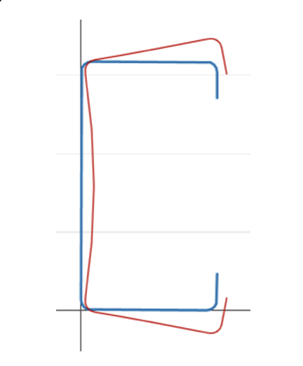
The buckling classes are organized into three main groups, globale, Locale, and distortional, depending on the failure type.
Local buckling: Buckling that involves significant distortion of the cross-section, ma questa distorsione include solo la rotazione, non traduzione, alle linee di piega interne [2].
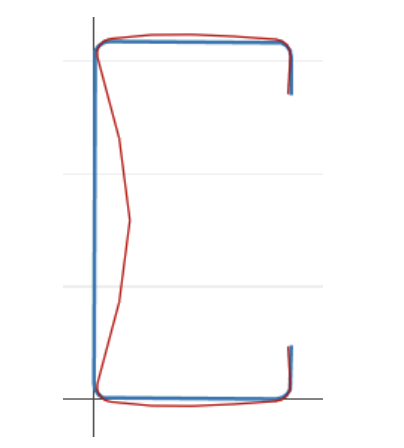
Instabilità distorsiva: Buckling that involves significant distortion of the cross-section, ma questa distorsione include rotazione e traslazione in una o più linee di piega interne di un membro [2].
Instabilità globale: Instabilità che non comporti distorsione della sezione trasversale, invece la traduzione (flessione) e/o rotazione (torsione) si verifica l'intera sezione trasversale [2].
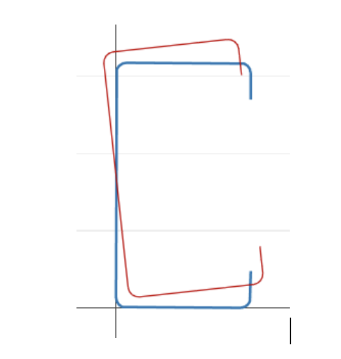
Da questa definizione possiamo dedurre che esiste una forte correlazione geometrica tra la classificazione dell'instabilità e la forma deformata, mostriamo la deformata per ogni punto della curva della firma.
DSM Factors
Metodo della striscia finita nel generatore di sezioni SkyCiv
SkyCiv has a Direct Strength Method Calculator built into our Section Analysis Software (Il Generatore di Sezioni SkyCiv) which can automatically calculate the key DSM factors for any custom cold formed steel shape. Simply start from the Section Builder module by loading in a CFS section and clicking Design -> Acciaio stampato a freddo:
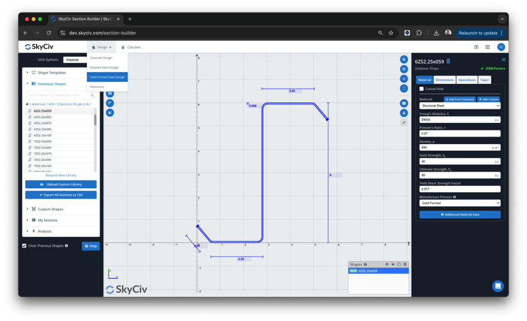
Da qui, the DSM factors will be automatically calculated, ready for the user to review and submit:
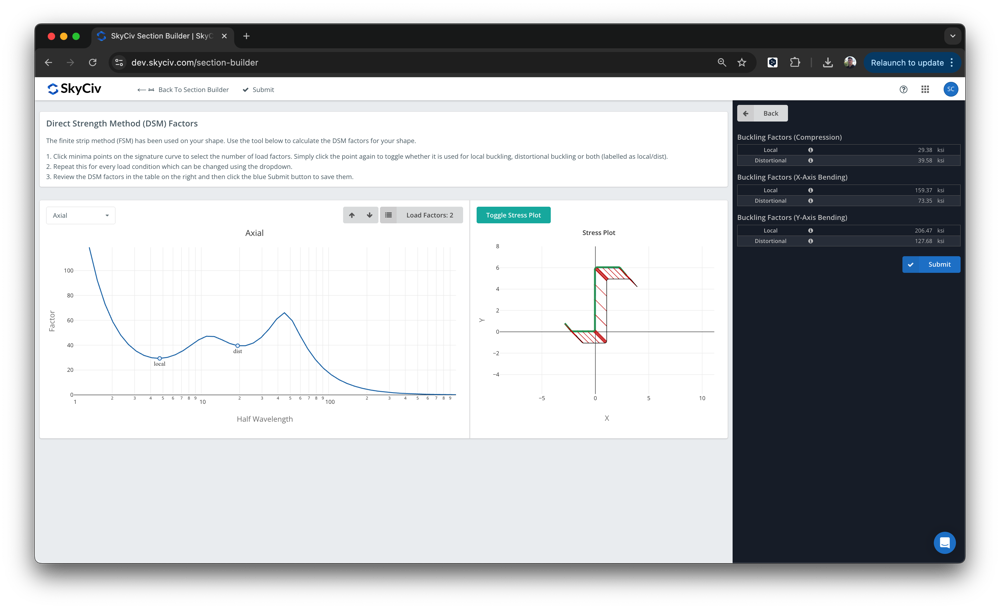
Il software è basato su SkyCiv Sezione Builder, sotto Design – Formato a freddo. I minimi di buckling locale e distorsivo verranno rilevati automaticamente, tuttavia gli utenti possono sovrascrivere questi valori. Una volta inviato, questi fattori verranno poi utilizzati nella progettazione dello SkyCiv AISI (2016) e AS4600 (2018) moduli di progettazione integrata.
Nel modulo di analisi dell'instabilità elastica SkyCiv, ci sono alcune ipotesi e considerazioni importanti che qui chiariamo. Esploreremo questi di seguito:
Maglia di elementi
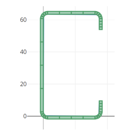
The mesh of the elements is produced automatically and can be viewed in the right chart, i filetti vengono divisi in 4 elementi, e la linea retta dentro 4 anche gli elementi.
Lunghezze di analisi
Le lunghezze utilizzate per eseguire l'analisi Finite Strip sono definite per impostazione predefinita come uno spazio logaritmico da 0 a 10^3 nel sistema di unità imperiali e da 0 a 10^3,5 nel sistema metrico.
Condizioni di carico
We calculate the signature curve for 5 different load conditions:
- Axial load
- Bending moment in X axis, positivo
- Bending moment in X axis, negativo
- Bending moment in Y axis, positivo
- Bending moment in Y axis, negativo
Condizioni al contorno
The analysis is performed assuming the model is pinned and free to warp at both ends.
Signature Curve
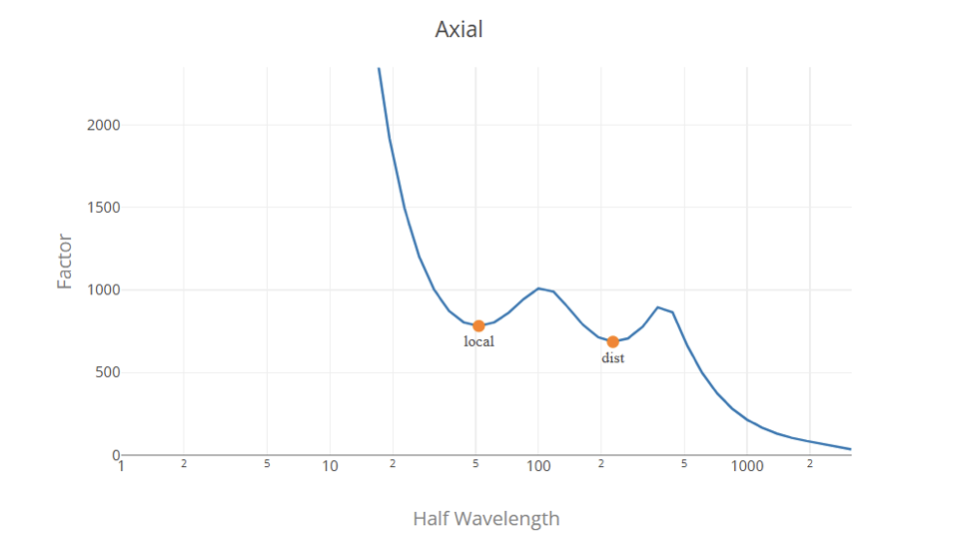
The signature curve is constructed using the conventional Finite Strip Method, Fy is normalized (Fy = 1) so the load factors are presented in pressure units (MPa or ksi according to the unit system).
Load Factor Selection
Generalmente, the load factors are the local minimum points in the signature curve, il primo rappresenta il fattore di carico critico per l'instabilità locale e il secondo rappresenta il fattore di carico critico per l'instabilità distorsiva. Determinare il fattore di carico globale dalla curva di firma è un compito difficile poiché non esiste un punto minimo locale nella curva di firma. Quindi, la soluzione più appropriata è utilizzare i fattori di carico di instabilità locale e distorsivo da un'analisi a strisce finite e il fattore di instabilità globale utilizzando le formule classiche.
Utilizziamo un algoritmo per trovare e classificare i fattori di carico nella curva di firma. Tuttavia, this does not ensure a correct classification in all the cases, and this does not replace the engineering judgment, invitiamo l'utente a rivedere i valori e modificarli se necessario prima dell'invio.
Riferimenti
- Specifiche nordamericane per la progettazione di elementi strutturali in acciaio formati a freddo, 2016 Edizione, Istituto americano del ferro e dell'acciaio.
- Metodo della forza diretta (DSM) Guida alla progettazione, 2006, Comitato per le specifiche per la progettazione di elementi strutturali in acciaio formati a freddo.
- Analisi di instabilità di elementi in acciaio formati a freddo utilizzando CUFSM: metodi convenzionali e vincolati a strisce finite, B.W. Schafer e S. Adany, 2006, 18esima Conferenza Internazionale Specialistica sulle Strutture in Acciaio Formate a Freddo.

