Exemplo de design da placa de base usando CSA S16:19 e CSA A23.3:19
Declaração de problemas
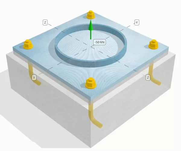
Determine se a conexão de placa coluna para base projetada é suficiente para uma carga de tensão de 50 kN.
Dados dados
Coluna:
Seção de coluna: HS324X9.5
Área da coluna: 9410 milímetros2
Material da coluna: 230G
Placa Base:
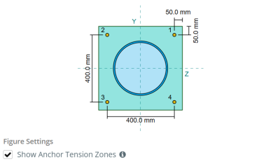
Dimensões da placa de base: 500 mm x 500 milímetros
Espessura da placa de base: 20 milímetros
Material da placa de base: 230G
Grout:
Espessura do rejunte: 20 milímetros
Concreto:
Dimensões concretas: 550 mm x 550 milímetros
Espessura do concreto: 200 milímetros
Material concreto: 20.68 MPa
Rachado ou sem crack: Rachado
Âncoras:
Diâmetro da âncora: 19.1 milímetros
Comprimento eficaz de incorporação: 130.0 milímetros
Comprimento do gancho: 60milímetros
Âncora a distância da face da coluna: 120.84 milímetros
Soldas:
Tipo de solda: CJP
Classificação de metal de enchimento: E43xx
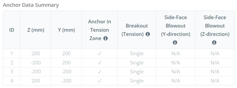
Dados de âncora (a partir de Calculadora Skyciv):
Modelo na ferramenta gratuita SkyCiv
Modele o design da placa de base acima usando nossa ferramenta online gratuita hoje mesmo! Não é necessária inscrição.
Definições
Caminho de carga:
Quando uma placa de base é submetida a elevada (tração) forças, Essas forças são transferidas para as hastes de ancoragem, que por sua vez induzem momentos de flexão na placa de base. A ação de flexão pode ser visualizada como Cantilever dobrando ocorrendo ao redor dos flanges ou da seção da coluna, dependendo de onde as âncoras estão posicionadas.
No Software de design de placa de base SkyCiv, apenas âncoras localizadas dentro do zona de tensão âncora são considerados eficazes para resistir à elevação. Esta zona normalmente inclui áreas próximas aos flanges ou web da coluna. No caso de um coluna circular, a zona de tensão da ancoragem inclui toda a área fora do perímetro do pilar. Âncoras fora desta zona não contribuem para a resistência da tensão e são excluídas dos cálculos de elevação.
Para determinar a área efetiva da placa de base que resiste, uma 45-dispersão de grau é assumido a partir da linha central de cada haste de ancoragem em direção à face da coluna. Esta dispersão define o Comprimento eficaz da solda e ajuda a estabelecer o largura de flexão eficaz da placa.
A suposição simplifica a análise da placa de base, aproximando -se de como a força de elevação se espalha pela placa.
Grupos de âncora:
A Software de design de placa de base SkyCiv inclui um recurso intuitivo que identifica quais âncoras fazem parte de um grupo âncora para avaliar fuga de concreto e Blowout de concreto lateral falhas.
A grupo âncora consiste em múltiplas âncoras com profundidades de incorporação eficazes semelhantes e espaçamento, e estão próximos o suficiente para que seu As áreas de resistência projetadas se sobrepõem. Quando as âncoras são agrupadas, Suas capacidades são combinadas para resistir à força de tensão total aplicada ao grupo.
Âncoras que não atendem aos critérios de agrupamento são tratadas como âncoras únicas. Nesse caso, Somente a força de tensão na âncora individual é verificada contra sua própria área de resistência efetiva.
Cálculos passo a passo
Verificar #1: Calcule a capacidade de solda
Aplicando Cargas Sísmicas, precisamos calcular a carga por âncora e determinar o comprimento efetivo de solda para cada âncora. A Comprimento eficaz da solda é baseado em um 45° linha de dispersão desenhado do centro da âncora até a face da coluna. Se esta linha de 45° não cruzar a coluna, a pontos tangentes são usados em vez disso. Além disso, se as âncoras estiverem bem espaçadas, o comprimento efetivo da solda é reduzido para evitar sobreposição. Finalmente, a soma de todos os comprimentos efetivos de solda não deve exceder o comprimento real soldável disponível ao longo da circunferência da coluna.
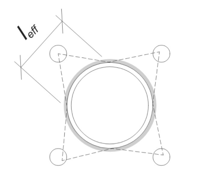
Vamos aplicar isso ao nosso exemplo. Com base na geometria dada, a linha de 45° da âncora não cruza a coluna. Como um resultado, o comprimento do arco entre os pontos tangentes é usado em vez disso. Este comprimento de arco também deve levar em conta quaisquer âncoras adjacentes, com quaisquer porções sobrepostas subtraídas para evitar contagem dupla. O comprimento do arco calculado é:
\(
eu_{\texto{arco}} = 254.47 \, \texto{milímetros}
\)
Este cálculo do comprimento do arco é totalmente automatizado no software SkyCiv Base Plate Design, mas também pode ser realizado manualmente usando métodos trigonométricos. Você pode experimentar a ferramenta gratuita neste link.
Considerando o comprimento soldável disponível ao longo da circunferência do pilar, a final Comprimento eficaz da solda é:
\(
eu_{\texto{ef}} = min left( eu_{\texto{arco}}, \fratura{\pi d_{\texto{col}}}{n_{uma,t}} \direito) = min left( 254.47 \, \texto{milímetros}, \fratura{\PI Times 324 \, \texto{milímetros}}{4} \direito) = 254.47 \, \texto{milímetros}
\)
A continuação, Vamos calcular o carga por âncora. Para um determinado conjunto de quatro (4) âncoras, A carga por âncora é:
\(
T_{você,\texto{âncora}} = frac{N_x}{n_{uma,t}} = frac{50 \, \texto{kN}}{4} = 12.5 \, \texto{kN}
\)
Usando o comprimento efetivo calculado da solda, agora podemos calcular o força necessária por unidade de comprimento agindo na solda.
\(
v_f = frac{T_{você,\texto{âncora}}}{eu_{\texto{ef}}} = frac{12.5 \, \texto{kN}}{254.47 \, \texto{milímetros}} = 0.049122 \, \texto{kN / mm}
\)
Agora, nós nos referimos a CSA S16:19 Cláusula 13.13.3.1 Para calcular o resistência fatorada da penetração completa da junta (CJP) soldar. Isto requer a resistência do metal base, expresso em força por unidade de comprimento, para os materiais da coluna e da placa de base.
\(
v_{r,\texto{bm}} = phi esquerda( \Min esquerda( F_{Y,\texto{col}} t_{\texto{col}}, F_{Y,\texto{pb}} t_{\texto{pb}} \direito) \direito)
\)
\(
v_{r,\texto{bm}} = 0.9 \times left( \Min esquerda( 230 \, \texto{MPa} \vezes 9.53 \, \texto{milímetros}, 230 \, \texto{MPa} \vezes 20 \, \texto{milímetros} \direito) \direito) = 1.9727 \, \texto{kN / mm}
\)
Desde a 0.049122 kN / mm < 1.9727 kN / mm, A capacidade de solda é suficiente.
Verificar #2: Calcule a capacidade de rendimento flexural da placa de base devido à carga de tensão
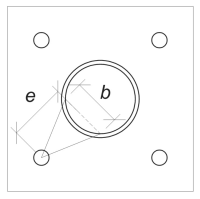
Usando a carga por âncora e o distância de deslocamento do centro da âncora até a face da coluna, O momento aplicado à placa de base pode ser calculado usando um em balanço suposição. Para uma coluna circular, a excentricidade da carga é determinada considerando a sagitta do arco soldado, e pode ser calculado da seguinte forma:
\(
e_{\texto{cano}} =d_o + r_{\texto{col}} \deixou( 1 – \cos esquerda( \fratura{eu_{\texto{ef}}}{2 r_{\texto{col}}} \direito) \direito)
\)
\(
e_{\texto{cano}} = 120.84 \, \texto{milímetros} + 162 \, \texto{milímetros} \times left( 1 – \cos esquerda( \fratura{254.47 \, \texto{milímetros}}{2 \vezes 162 \, \texto{milímetros}} \direito) \direito) = 168.29 \, \texto{milímetros}
\)
O momento induzido é calculado como:
\(
M_f = T_{você,\texto{âncora}} e_{\texto{cano}} = 12.5 \, \texto{kN} \vezes 168.29 \, \texto{milímetros} = 2103.6 \, \texto{kN} \CDOT Text{milímetros}
\)
A continuação, determinaremos a largura de flexão da placa de base. Por esta, nós usamos o comprimento do acorde correspondente ao arco de solda efetivo.
\(
\teta_{\texto{trabalhar}} = frac{eu_{\texto{ef}}}{0.5 d_{\texto{col}}} = frac{254.47 \, \texto{milímetros}}{0.5 \vezes 324 \, \texto{milímetros}} = 1.5708
\)
\(
b = d_{\texto{col}} \deixou( \pecado esquerda( \fratura{\teta_{\texto{trabalhar}}}{2} \direito) \direito) = 324 \, \texto{milímetros} \times left( \pecado esquerda( \fratura{1.5708}{2} \direito) \direito) = 229.1 \, \texto{milímetros}
\)
Finalmente, Podemos calcular o fatorado resistência à flexão da placa de base usando CSA S16:19 Cláusula 13.5.
\(
M_r = phi F_{Y,\texto{pb}} Z_{\texto{ef}} = 0.9 \vezes 230 \, \texto{MPa} \vezes 22910 \, \texto{milímetros}^3 = 4742.4 \, \texto{kN} \CDOT Text{milímetros}
\)
Onde,
\(
Z_{\texto{ef}} = frac{b (t_{\texto{pb}})^ 2}{4} = frac{229.1 \, \texto{milímetros} \vezes (20 \, \texto{milímetros})^ 2}{4} = 22910 \, \texto{milímetros}^ 3
\)
Desde a 2103.6 KN-MM < 4742.4 KN-MM, A capacidade de rendimento flexural da placa de base é suficiente.
Verificar #3: Calcule a capacidade de tração à haste de ancoragem
Para avaliar a capacidade de tração da haste de ancoragem, nos referimos ao CSA A23.3:19 Cláusula D.6.1.2 e CSA S16:19 Cláusula 25.3.2.1.
Primeiro, Nós determinamos o resistência à tração especificada do aço âncora. Este é o menor valor permitido por CSA A23.3:19 Cláusula D.6.1.2.
\(
f_{\texto{uta}} = min left( F_{você,\texto{anc}}, 1.9 F_{Y,\texto{anc}}, 860 \direito) = min left( 400 \, \texto{MPa}, 1.9 \vezes 248.2 \, \texto{MPa}, 860.00 \, \texto{MPa} \direito) = 400 \, \texto{MPa}
\)
A continuação, Nós determinamos o Área transversal eficaz da haste de ancoragem em tensão usando Manual de Projeto de Concreto CAC, 3Edição RD, Tabela 12.3.
\(
UMA_{eu sei,N} = 215 \, \texto{milímetros}^ 2
\)
Com esses valores, nós aplicamos CSA A23.3:19 Eq. D.2 Para calcular o resistência à tração fatorada da haste de ancoragem.
\(
N_{\texto{sar}} = A_{eu sei,N} \phi_s f_{\texto{uta}} R = 215 \, \texto{milímetros}^2 Times 0.85 \vezes 400 \, \texto{MPa} \vezes 0.8 = 58.465 \, \texto{kN}
\)
Além disso, Nós avaliamos o resistência à tração fatorada de acordo com CSA S16:19 Cláusula 25.3.2.1.
\(
T_r = phi_{ar} 0.85 UMA_{ar} F_{você,\texto{anc}} = 0.67 \vezes 0.85 \vezes 285.02 \, \texto{milímetros}^2 Times 400 \, \texto{MPa} = 64.912 \, \texto{kN}
\)
Depois de comparar os dois, identificamos que a resistência fatorada calculada usando CSA A23.3:19 governa neste caso.
Lembre -se do calculado anteriormente carga de tensão por âncora:
\(
N_{fa} = frac{N_x}{n_{uma,t}} = frac{50 \, \texto{kN}}{4} = 12.5 \, \texto{kN}
\)
Desde a 12.5 kN < 58.465 kN, A capacidade de tração da haste da ancoragem é suficiente.
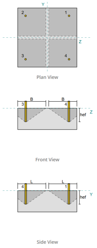
Verificar #4: Calcule a capacidade de fuga de concreto na tensão
Antes de calcular a capacidade de fuga, devemos primeiro determinar se o membro se qualifica como um membro estreito. De acordo com CSA A23.3:19 Cláusula D.6.2.3, o membro não atende aos critérios para um membro restrito. Portanto, o dado comprimento eficaz de incorporação será usado nos cálculos.
Usando CSA A23.3:19 Eq. D.5, nós calculamos o Área máxima de cone de concreto projetado para uma única âncora, com base no comprimento efetivo de incorporação.
\(
UMA_{Lembrar} = 9 (h_{ef,s1})A partir da elevação do solo gerada a partir das elevações do Google 9 \vezes (130 \, \texto{milímetros})A partir da elevação do solo gerada a partir das elevações do Google 152100 \, \texto{milímetros}^ 2
\)
similarmente, usamos o comprimento efetivo de incorporação para calcular o Área de cone de concreto projetada real da única âncora.
\(
UMA_{Nc} = L_{Nc} B_{Nc} = 270 \, \texto{milímetros} \vezes 270 \, \texto{milímetros} = 72900 \, \texto{milímetros}^ 2
\)
Onde,
\(
EU_{Nc} = left( \Min esquerda( c_{\texto{deixou},s1}, 1.5 h_{ef,s1} \direito) \direito) + \deixou( \Min esquerda( c_{\texto{direito},s1}, 1.5 h_{ef,s1} \direito) \direito)
\)
\(
EU_{Nc} = left( \Min esquerda( 475 \, \texto{milímetros}, 1.5 \vezes 130 \, \texto{milímetros} \direito) \direito) + \deixou( \Min esquerda( 75 \, \texto{milímetros}, 1.5 \vezes 130 \, \texto{milímetros} \direito) \direito)
\)
\(
EU_{Nc} = 270 \, \texto{milímetros}
\)
\(
B_{Nc} = left( \Min esquerda( c_{\texto{figura superior},s1}, 1.5 h_{ef,s1} \direito) \direito) + \deixou( \Min esquerda( c_{\texto{figura inferior},s1}, 1.5 h_{ef,s1} \direito) \direito)
\)
\(
B_{Nc} = left( \Min esquerda( 75 \, \texto{milímetros}, 1.5 \vezes 130 \, \texto{milímetros} \direito) \direito) + \deixou( \Min esquerda( 475 \, \texto{milímetros}, 1.5 \vezes 130 \, \texto{milímetros} \direito) \direito)
\)
\(
B_{Nc} = 270 \, \texto{milímetros}
\)
A continuação, Nós avaliamos o fatorado resistência básica à ruptura do concreto de uma única âncora usando CSA A23.3:19 Eq. D.6
\(
N_{br} =k_c phi lambda_a sqrt{\fratura{f’_c}{\texto{MPa}}} \deixou( \fratura{h_{ef,s1}}{\texto{milímetros}} \direito)^{1.5} R N
\)
\(
N_{br} = 10 \vezes 0.65 \vezes 1 \times sqrt{\fratura{20.68 \, \texto{MPa}}{1 \, \texto{MPa}}} \times left( \fratura{130 \, \texto{milímetros}}{1 \, \texto{milímetros}} \direito)^{1.5} \vezes 1 \vezes 0.001 \, \texto{kN} = 43.813 \, \texto{kN}
\)
Onde,
- \(inclui cálculos detalhados passo a passo{c} = 10\) para âncoras fundidas
- \(\lambda = 1.0 \) para concreto de peso normal
Agora, Avaliamos os efeitos da geometria calculando o fator de efeito de borda.
A distância da borda mais curta do grupo âncora é determinada como:
\(
c_{uma,\texto{min}} = min left( c_{\texto{deixou},s1}, c_{\texto{direito},s1}, c_{\texto{figura superior},s1}, c_{\texto{figura inferior},s1} \direito) = min left( 475 \, \texto{milímetros}, 75 \, \texto{milímetros}, 75 \, \texto{milímetros}, 475 \, \texto{milímetros} \direito) = 75 \, \texto{milímetros}
\)
De acordo com CSA A23.3:19 Eq. D.10 e D.11, a fuga fator de efeito de borda é:
\(
\Psi_{ed,N} = min left( 1.0, 0.7 + 0.3 \deixou( \fratura{c_{uma,\texto{min}}}{1.5 h_{ef,s1}} \direito) \direito) = min left( 1, 0.7 + 0.3 \times left( \fratura{75 \, \texto{milímetros}}{1.5 \vezes 130 \, \texto{milímetros}} \direito) \direito) = 0.81538
\)
Além disso, ambos fator de rachadura quanto pelo fator de divisão são tomados como:
\(
\Psi_{c,N} = 1
\)
\(
\Psi_{cp,N} = 1
\)
Então, Combinamos todos esses fatores e usamos ACI 318-19 Eq. 17.6.2.1b para avaliar o fatorado resistência à ruptura do concreto da única âncora:
\(
N_{cbr} = left( \fratura{UMA_{Nc}}{UMA_{Lembrar}} \direito) \Psi_{ed,N} \Psi_{c,N} \Psi_{cp,N} N_{br} = left( \fratura{72900 \, \texto{milímetros}^ 2}{152100 \, \texto{milímetros}^ 2} \direito) \vezes 0.81538 \vezes 1 \vezes 1 \vezes 43.813 \, \texto{kN} = 17.122 \, \texto{kN}
\)
Lembre -se do calculado anteriormente carga de tensão por âncora:
\(
N_{fa} = frac{N_x}{n_{uma,s}} = frac{50 \, \texto{kN}}{4} = 12.5 \, \texto{kN}
\)
Desde a 12.5 kN < 17.122 kN A capacidade de fuga de concreto é suficiente.
Este cálculo de ruptura concreto é baseado no Anchor ID #1. A mesma capacidade será aplicada às outras âncoras devido ao design simétrico.
Verificar #5: Calcule a capacidade de extração de âncora
A capacidade de extração de uma âncora é governada pela resistência em sua extremidade incorporada. Para âncoras com gancho, depende do comprimento do gancho.
Nós calculamos o resistência básica ao arrancamento da âncora fatorada por CSA A23.3:19 Eq. D.17.
\(
N_{pr} = Psi_{c,p} 0.9 \phi (f’_c) e_h d_a R = 1 \vezes 0.9 \vezes 0.65 \vezes (20.68 \, \texto{MPa}) \vezes 60 \, \texto{milímetros} \vezes 19.05 \, \texto{milímetros} \vezes 1 = 13.828 \, \texto{kN}
\)
Lembre -se do calculado anteriormente carga de tensão por âncora:
\(
N_{fa} = frac{N_x}{n_{uma,t}} = frac{50 \, \texto{kN}}{4} = 12.5 \, \texto{kN}
\)
Desde a 12.5 kN < 13.828 kN, A capacidade de extração de âncora é suficiente.
Verificar #6: Calcule a capacidade de explosão lateral na direção y
Este cálculo não é aplicável para âncoras em gancho.
Verificar #7: Calcule a capacidade de explosão lateral na direção z
Este cálculo não é aplicável para âncoras em gancho.
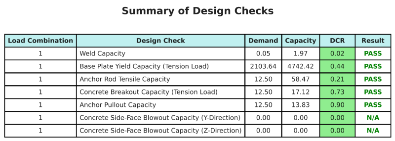
Resumo do projeto
A Software de design de placa de base skyciv pode gerar automaticamente um relatório de cálculo passo a passo para este exemplo de design. Ele também fornece um resumo dos cheques executados e suas proporções resultantes, facilitando o entendimento da informação. Abaixo está uma tabela de resumo de amostra, que está incluído no relatório.
Relatório de amostra de Skyciv
Veja o nível de detalhe e clareza que você pode esperar de um relatório de design de placa base SkyCiv. O relatório inclui todas as principais verificações de projeto, equações, e resultados apresentados em um formato claro e fácil de ler. É totalmente compatível com os padrões de design. Clique abaixo para ver um exemplo de relatório gerado usando a calculadora de placa base SkyCiv.
Compre software de placa de base
Compre a versão completa do módulo de design da placa de base por conta própria, sem quaisquer outros módulos SkyCiv. Isso oferece um conjunto completo de resultados para o design da placa de base, incluindo relatórios detalhados e mais funcionalidade.