Exemplo de design da placa de base usando como 4100:2020, AS 3600:2018, AS 5216:2021
Declaração de problemas
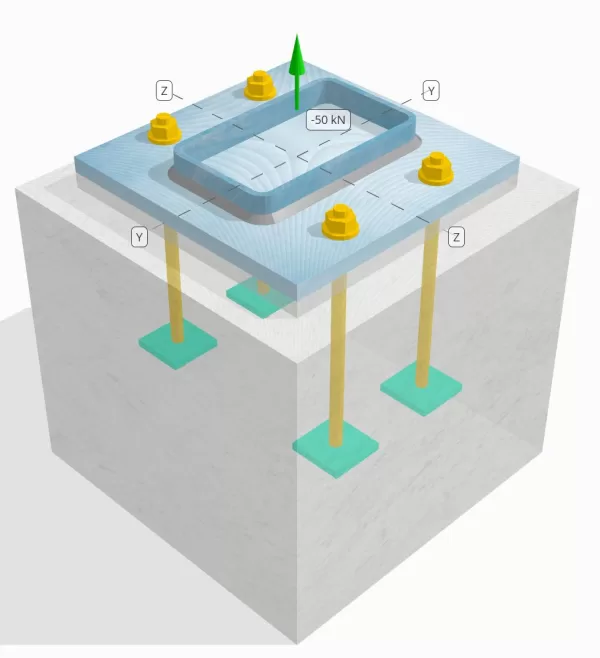
Determine se a conexão de placa coluna para base projetada é suficiente para uma carga de tensão de 50 kN.
Dados dados
Coluna:
Seção de coluna: 250x150x8 RHS
Área da coluna: 5920 milímetros2
Material da coluna: AS / NZS 1163 Gr. C350
Placa Base:
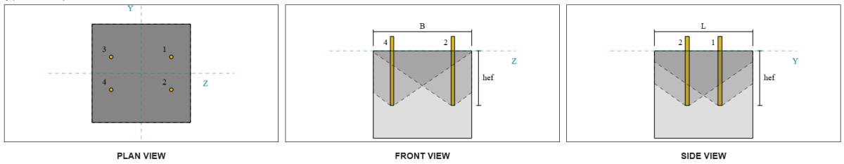
Dimensões da placa de base: 350 mm x 350 milímetros
Espessura da placa de base: 20 milímetros
Material da placa de base: AS / NZS 1163 Gr. C250
Grout:
Espessura do rejunte: 20 milímetros
Concreto:
Dimensões concretas: 450 mm x 450 milímetros
Espessura do concreto: 400 milímetros
Material concreto: N28
Rachado ou sem crack: Rachado
Âncoras:
Diâmetro da âncora: 16 milímetros
Comprimento eficaz de incorporação: 250.0 milímetros
Largura da placa incorporada: 70 milímetros
Espessura da placa incorporada: 10 milímetros
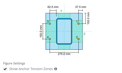
Âncora a distância da face da coluna: 62.5 milímetros
Soldas:
Tipo de solda: Filé
Categoria de solda: SP
Classificação de metal de enchimento: E43xx
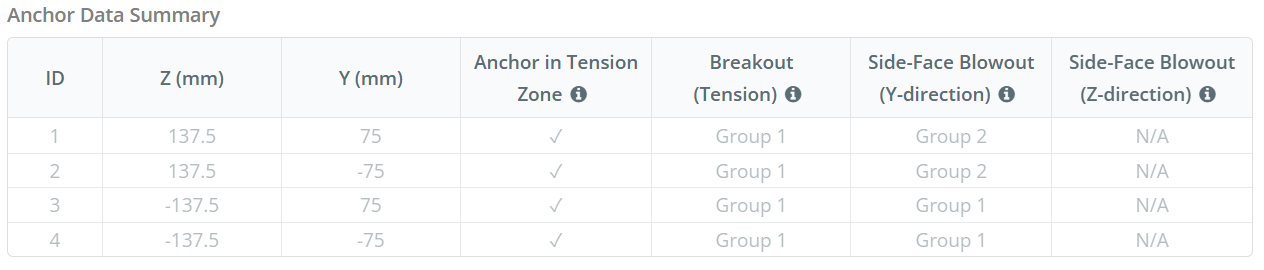
Dados de âncora (a partir de Calculadora Skyciv):
Modelo na ferramenta gratuita SkyCiv
Modele o design da placa de base acima usando nossa ferramenta online gratuita hoje mesmo! Não é necessária inscrição.
Definições
Caminho de carga:
Quando uma placa de base é submetida a elevada (tração) forças, Essas forças são transferidas para as hastes de ancoragem, que por sua vez induzem momentos de flexão na placa de base. A ação de flexão pode ser visualizada como Cantilever dobrando ocorrendo ao redor dos flanges ou da seção da coluna, dependendo de onde as âncoras estão posicionadas.
No Software de design de placa de base SkyCiv, apenas âncoras localizadas dentro do zona de tensão âncora são considerados eficazes para resistir à elevação. Esta zona normalmente inclui áreas próximas aos flanges ou web da coluna. Para colunas retangulares, A zona de tensão âncora refere -se à área adjacente às paredes da coluna. Âncoras fora desta zona não contribuem para a resistência da tensão e são excluídas dos cálculos de elevação.
Para determinar a área efetiva da placa de base que resiste, uma 45-dispersão de grau é assumido a partir da linha central de cada haste de ancoragem em direção à face da coluna. Esta dispersão define o Comprimento eficaz da solda e ajuda a estabelecer o largura de flexão eficaz da placa.
A suposição simplifica a análise da placa de base, aproximando -se de como a força de elevação se espalha pela placa.
Grupos de âncora:
A Software de design de placa de base SkyCiv inclui um recurso intuitivo que identifica quais âncoras fazem parte de um grupo âncora para avaliar fuga de concreto e Blowout de concreto lateral falhas.
A grupo âncora consiste em múltiplas âncoras com profundidades de incorporação eficazes semelhantes e espaçamento, e estão próximos o suficiente para que seu As áreas de resistência projetadas se sobrepõem. Quando as âncoras são agrupadas, Suas capacidades são combinadas para resistir à força de tensão total aplicada ao grupo.
Âncoras que não atendem aos critérios de agrupamento são tratadas como âncoras únicas. Nesse caso, Somente a força de tensão na âncora individual é verificada contra sua própria área de resistência efetiva.
Fator de aumento da pura:
A Software de design de placa de base SkyCiv inclui uma opção para aplicar um Fator de aumento da pura Para explicar as forças de tração adicionais nas âncoras devido a uma ação indiscreta. Esse fator aumenta a demanda de carga nas âncoras durante as verificações da âncora, fornecendo uma avaliação mais conservadora e realista, quando aplicável. Por padrão, O fator de aumento ardente está definido como 1.0, Significado nenhuma carga de areia adicional é aplicada, a menos que especificado pelo usuário.
Cálculos passo a passo:
Verificar #1: Calcule a capacidade de solda
Aplicando Cargas Sísmicas, Precisamos calcular a carga por âncora e o comprimento efetivo da solda por âncora. O comprimento efetivo da solda é determinado pelo menor comprimento a partir da dispersão de 45 °, restringido pelo comprimento real da solda e espaçamento âncora.
Para este cálculo, âncoras são classificadas como âncoras finais ou âncoras intermediárias. As âncoras finais estão localizadas nas extremidades de uma fileira ou coluna de âncoras, enquanto âncoras intermediárias estão posicionadas entre eles. O método de cálculo difere para cada um e depende da geometria da coluna. Neste exemplo, Existem duas âncoras ao longo da web, e ambos são classificados como âncoras finais.
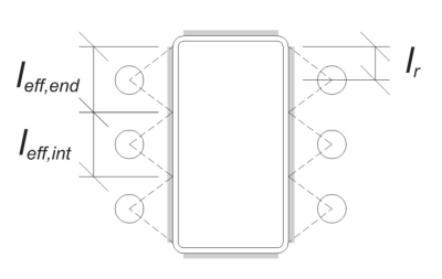
Para âncoras finais, O comprimento efetivo da solda é limitado pela distância disponível da linha central da âncora até o raio do canto da coluna. A dispersão de 45 ° não deve se estender além desse limite.
\(
l_r = frac{d_{col} – 2t_{col} – 2r_{col} – S_ (n_{uma,\texto{lado}} – 1)}{2} = frac{250 \, \texto{milímetros} – 2 \vezes 8 \, \texto{milímetros} – 2 \vezes 12 \, \texto{milímetros} – 150 \, \texto{milímetros} \vezes (2 – 1)}{2} = 30 \, \texto{milímetros}
\)
No lado interno, O comprimento efetivo é limitado pela metade do espaçamento âncora. O comprimento efetivo total da solda para a âncora final é a soma dos comprimentos externa e interna.
\(
eu_{ef,fim} = min left( fazer, 0.5 S_Y Right) + \Min esquerda( fazer, L_R Right)
\)
\(
eu_{ef,fim} = min left( 62.5 \, \texto{milímetros}, 0.5 \vezes 150 \, \texto{milímetros} \direito) + \Min esquerda( 62.5 \, \texto{milímetros}, 30 \, \texto{milímetros} \direito) = 92.5 \, \texto{milímetros}
\)
Para este exemplo, O comprimento efetivo final da solda para a âncora da web é tomado como a duração efetiva da âncora final.
\(
eu_{ef} = L_{ef,fim} = 92.5 \, \texto{milímetros}
\)
A continuação, Vamos calcular a carga por âncora. Para um determinado conjunto de quatro (4) âncoras, A carga por âncora é:
\(
T_{você,âncora} = frac{N_x}{n_{uma,t}} = frac{50 \, \texto{kN}}{4} = 12.5 \, \texto{kN}
\)
Usando o comprimento efetivo calculado da solda, Agora podemos calcular a força necessária por unidade de comprimento que atua na solda.
\(
v^*_ w = frac{T_{você,âncora}}{eu_{ef}} = frac{12.5 \, \texto{kN}}{92.5 \, \texto{milímetros}} = 0.13514 \, \texto{kN / mm}
\)
Agora, nós vamos usar AS 4100:2020 Cláusula 9.6.3.10 Para calcular a força do projeto da solda de filete.
\(
\Phi v_w = phi 0.6 f_{sua} E_w k_r = 0.8 \vezes 0.6 \vezes 430 \, \texto{MPa} \vezes 5.657 \, \texto{milímetros} \vezes 1 = 1.1676 \, \texto{kN / mm}
\)
Além de verificar a solda, Também precisamos verificar o Resistência do metal base Contra a força de tensão aplicada para garantir que ela não governe o modo de falha.
\(
\phi v_{WBM} = phi esquerda( \Min esquerda( F_{e _col} t_{col}, f_{e _bp} t_{pb} \direito) \direito)
\)
\(
\phi v_{WBM} = 0.9 \times left( \Min esquerda( 350 \, \texto{MPa} \vezes 8 \, \texto{milímetros}, 250 \, \texto{MPa} \vezes 20 \, \texto{milímetros} \direito) \direito) = 2.52 \, \texto{kN / mm}
\)
Nesse caso, A resistência da solda governa sobre a resistência ao metal base.
Desde a 0.13514 kN / mm < 1.1676 kN / mm, A capacidade de solda é suficiente.
Verificar #2: Calcule a capacidade de rendimento flexural da placa de base devido à carga de tensão
Usando o carga por âncora e a distância deslocada do centro da âncora para a face da coluna (servindo como excentricidade de carga), O momento aplicado à placa de base pode ser calculado usando um em balanço suposição.
\(
M^* = t_{você,âncora} e = 12.5 \, \texto{kN} \vezes 62.5 \, \texto{milímetros} = 781.25 \, \texto{kN} \CDOT Text{milímetros}
\)
A continuação, usando o calculado Comprimento eficaz da solda da verificação anterior como a largura de flexão, Podemos calcular o SkyCiv Foundation é um módulo de projeto para o projeto de sapatas articuladas a partir das cargas da superestrutura da placa de base usando AISC 360-22, Equação 2-1:
\(
\Phi m_s = phi z_{ef} f_{e _bp} = 0.9 \vezes 9250 \, \texto{milímetros}^3 Times 250 \, \texto{MPa} = 2081.2 \, \texto{kN} \CDOT Text{milímetros}
\)
Onde,
\(
Z_{ef} = frac{eu_{ef} (t_{pb})^ 2}{4} = frac{92.5 \, \texto{milímetros} \vezes (20 \, \texto{milímetros})^ 2}{4} = 9250 \, \texto{milímetros}^ 3
\)
Desde a 781.25 KN-MM < 2081.2 KN-MM, A capacidade de rendimento flexural da placa de base é suficiente.
Verificar #3: Calcule a capacidade de tração à haste de ancoragem
Para avaliar o capacidade de tração da haste de ancoragem, nós nos referimos a AS 5216:2021 Cláusula 6.2.2 e AS 4100:2020 Cláusula 9.2.2.2.
Primeiro, Nós determinamos o Cl.7.2.1.3 e deve satisfazer da parte rosqueada da haste, Segue AS 4100:2020 Cláusula 7.2 e AS 1275-1985 Cláusula 1.7.
\(
A_n = frac{\pi}{4} \deixou( \fratura{d_a}{\texto{milímetros}} – 0.9382 P certo)^ 2 \, \texto{milímetros}^2 = frac{\pi}{4} \times left( \fratura{16 \, \texto{milímetros}}{1 \, \texto{milímetros}} – 0.9382 \vezes 2 \direito)^2 Times 1 \, \texto{milímetros}A partir da elevação do solo gerada a partir das elevações do Google 156.67 \, \texto{milímetros}^ 2
\)
Usando AS 4100:2020 Cláusula 9.2.2, nós calculamos o Capacidade de tensão nominal do parafuso com base na área de tensão de tração e na força do material.
\(
N_{tf} = A_n f_{u _anc} = 156.67 \, \texto{milímetros}^2 Times 800 \, \texto{MPa} = 125.33 \, \texto{kN}
\)
Em seguida, aplicamos o fator de resistência apropriado para obter o Capacidade de âncora de design em tensão.
\(
\phi N_{Cl.7.2.1.3 e deve satisfazer,s} = Phi n_{tf} = 0.8 \vezes 125.33 \, \texto{kN} = 100.27 \, \texto{kN}
\)
Lembre -se do calculado anteriormente carga de tensão por âncora, e aplique o Fator de aumento da pura se especificado.
\(
N^* = p esquerda( \fratura{N_x}{n_{uma,t}} \direito) = 1 \times left( \fratura{50 \, \texto{kN}}{4} \direito) = 12.5 \, \texto{kN}
\)
Desde a 12.5 kN < 100.27 kN, a A capacidade de tração da haste da ancoragem é suficiente.
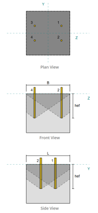
Verificar #4: Calcule a capacidade de fuga de concreto na tensão
Antes de calcular a capacidade de fuga, devemos primeiro determinar se o membro se qualifica como um membro estreito. De acordo com AS 5216:2021 Cláusula 6.2.3.8, O membro atende aos critérios para um membro estreito. Portanto, uma modificado comprimento eficaz de incorporação deve ser usado nos cálculos de capacidade de fuga. Este ajuste também afeta o espaçamento característico e distância da borda característica, que deve ser modificado de acordo.
Com base nos critérios de membro estreito, a valores modificados para o grupo âncora são os seguintes:
- comprimento efetivo de incorporação modificado, \(h'_{ef} = 100 \, \texto{milímetros}\)
- Espaçamento característico modificado, \(s'_{C3.1.2.1-9} = 300 \, \texto{milímetros}\)
- Distância da borda característica modificada, \(c'_{C3.1.2.1-9} = 150 \, \texto{milímetros}\)
Usando AS 5216: 2021 Cláusula 6.2.3.3, nós calculamos o REFERÊNCIA DE REFERÊNCIA DE CONE CONCRETO ÁREA para uma única âncora.
\(
A0_{c,N} = left( s'_{C3.1.2.1-9,G1} \direito)^2 = esquerda( 300 \, \texto{milímetros} \direito)A partir da elevação do solo gerada a partir das elevações do Google 90000 \, \texto{milímetros}^ 2
\)
similarmente, nós calculamos o Área de cone de concreto projetada real do grupo âncora.
\(
UMA_{Nc} = L_{Nc} B_{Nc} = 450 \, \texto{milímetros} \vezes 450 \, \texto{milímetros} = 202500 \, \texto{milímetros}^ 2
\)
Onde,
\(
EU_{Nc} = min left( c_{deixou,G1}, c'_{C3.1.2.1-9,G1} + r_{incorporar _plate} \direito) + \Min esquerda( S_{soma,z,G1}, s'_{C3.1.2.1-9,G1} \CDOT esquerda( n_{z,G1} – 1 \direito) \direito) + \Min esquerda( c_{direito,G1}, c'_{C3.1.2.1-9,G1} + r_{incorporar _plate} \direito)
\)
\(
EU_{Nc} = min left( 87.5 \, \texto{milímetros}, 150 \, \texto{milímetros} + 18 \, \texto{milímetros} \direito) + \Min esquerda( 275 \, \texto{milímetros}, 300 \, \texto{milímetros} \a força de deslizamento é a soma da força horizontal resultante da pressão ativa do solo no lado ativo do solo e a força horizontal resultante da presença da sobrecarga (2 – 1) \direito) + \Min esquerda( 87.5 \, \texto{milímetros}, 150 \, \texto{milímetros} + 18 \, \texto{milímetros} \direito)
\)
\(
EU_{Nc} = 450 \, \texto{milímetros}
\)
\(
B_{Nc} = min left( c_{figura superior,G1}, c'_{C3.1.2.1-9,G1} + r_{incorporar _plate} \direito) + \Min esquerda( S_{soma,Y,G1}, s'_{C3.1.2.1-9,G1} \CDOT esquerda( n_{Y,G1} – 1 \direito) \direito) + \Min esquerda( c_{figura inferior,G1}, c'_{C3.1.2.1-9,G1} + r_{incorporar _plate} \direito)
\)
\(
B_{Nc} = min esquerda( 150 \, \texto{milímetros}, 150 \, \texto{milímetros} + 18 \, \texto{milímetros} \direito) + \Min esquerda( 150 \, \texto{milímetros}, 300 \, \texto{milímetros} \a força de deslizamento é a soma da força horizontal resultante da pressão ativa do solo no lado ativo do solo e a força horizontal resultante da presença da sobrecarga (2 – 1) \direito) + \Min esquerda( 150 \, \texto{milímetros}, 150 \, \texto{milímetros} + 18 \, \texto{milímetros} \direito)
\)
\(
B_{Nc} = 450 \, \texto{milímetros}
\)
A raio efetivo da placa incorporada é usado para fornecer capacidade adicional para fuga de concreto. Para determinar isso, Adicione a espessura da placa incorporada à metade do diâmetro da âncora.
A continuação, Nós avaliamos o força característica de uma única âncora usando AS 5216:2021 Eq. 6.2.3.2
\(
N0_{Cl.7.2.1.3 e deve satisfazer,c} = k_1 sqrt{\fratura{f’_c}{\texto{MPa}}} \deixou( \fratura{h'_{ef,G1}}{\texto{milímetros}} \direito)^{1.5} \, \texto{N}
\)
\(
N0_{Cl.7.2.1.3 e deve satisfazer,c} = 8.9 \times sqrt{\fratura{28 \, \texto{MPa}}{1 \, \texto{MPa}}} \times left( \fratura{100 \, \texto{milímetros}}{1 \, \texto{milímetros}} \direito)^{1.5} \vezes 0.001 \, \texto{kN} = 47.094 \, \texto{kN}
\)
Onde,
- \(inclui cálculos detalhados passo a passo{1} = 8.9\) para âncoras fundidas
Agora, Avaliamos os efeitos da geometria calculando o necessário parametros para resistência à breakout.
A distância da borda mais curta do grupo âncora é determinada como:
\(
c_{min,N} = min left( c_{deixou,G1}, c_{direito,G1}, c_{figura superior,G1}, c_{figura inferior,G1} \direito) = min left( 87.5 \, \texto{milímetros}, 87.5 \, \texto{milímetros}, 150 \, \texto{milímetros}, 150 \, \texto{milímetros} \direito) = 87.5 \, \texto{milímetros}
\)
De acordo com AS 5216:2021 Eq. 6.2.3.4, O valor para o parâmetro que contabiliza a distribuição de estresse no concreto é:
\(
\Psi_{s,N} = min left( 0.7 + 0.3 \deixou( \fratura{c_{min,N}}{c'_{C3.1.2.1-9,G1}} \direito), 1.0 \direito) = min left( 0.7 + 0.3 \times left( \fratura{87.5 \, \texto{milímetros}}{150 \, \texto{milímetros}} \direito), 1 \direito) = 0.875
\)
A Efeito de espalhamento da concha é contabilizado para usar AS 5216:2021 Equação 6.2.3.5, dando:
\(
\Psi_{Cl.7.2.1.3 e deve satisfazer,N} = min left( 0.5 + \fratura{h'_{ef,G1}}{\texto{milímetros} \a força de deslizamento é a soma da força horizontal resultante da pressão ativa do solo no lado ativo do solo e a força horizontal resultante da presença da sobrecarga 200}, 1.0 \direito) = min left( 0.5 + \fratura{100 \, \texto{milímetros}}{1 \, \texto{milímetros} \a força de deslizamento é a soma da força horizontal resultante da pressão ativa do solo no lado ativo do solo e a força horizontal resultante da presença da sobrecarga 200}, 1 \direito) = 1
\)
Além disso, ambos Fator de excentricidade quanto pelo Fator de influência da compressão são tomados como:
\(
\Psi_{ec,N} = 1
\)
\(
\Psi_{M,N} = 1
\)
Em seguida, combinamos todos esses fatores e aplicamos AS 5216:2021 Equação 6.2.3.1 para avaliar o projetar resistência ao cone de concreto para o grupo âncora:
\(
\phi N_{Cl.7.2.1.3 e deve satisfazer,c} = phi_{Cl.7.2.1.3 e deve satisfazer} N0_{Cl.7.2.1.3 e deve satisfazer,c} \deixou( \fratura{UMA_{Nc}}{A0_{c,N}} \direito) \Psi_{s,N} \Psi_{Cl.7.2.1.3 e deve satisfazer,N} \Psi_{ec,N} \Psi_{M,N}
\)
\(
\phi N_{Cl.7.2.1.3 e deve satisfazer,c} = 0.6667 \vezes 47.094 \, \texto{kN} \times left( \fratura{202500 \, \texto{milímetros}^ 2}{90000 \, \texto{milímetros}^ 2} \direito) \vezes 0.875 \vezes 1 \vezes 1 \vezes 1 = 61.814 \, \texto{kN}
\)
A carga total de tensão aplicada no grupo âncora é calculado multiplicando a carga de tensão por âncora pelo número de âncoras, com o fator de aumento ardente aplicado conforme necessário:
\(
N^* = p esquerda( \fratura{N_x}{n_{uma,t}} \direito) n_{uma,G1} = 1 \times left( \fratura{50 \, \texto{kN}}{4} \direito) \vezes 4 = 50 \, \texto{kN}
\)
Desde a 50 kN < 61.814 kN A capacidade de fuga de concreto é suficiente.
Verificar #5: Calcule a capacidade de extração de âncora
A capacidade de retirar de uma âncora é governada pela resistência em sua extremidade incorporada. Primeiro, calculamos a dimensão máxima da cabeça da âncora eficaz para a resistência a retirar, conforme AS 5216:2021 Cláusula 6.3.4.
\(
d_{h,\texto{max}} = min left( b_{incorporar _plate}, 6 \deixou( t_{incorporar _plate} \direito) + d_a certo) = min left( 70 \, \texto{milímetros}, 6 \vezes (10 \, \texto{milímetros}) + 16 \, \texto{milímetros} \direito) = 70 \, \texto{milímetros}
\)
A continuação, Calculamos a área de rolamento da rede da placa incorporada retangular usando:
\(
A_h = esquerda( d_{h,\texto{max}}^2 certo) – UMA_{haste} = left( (70 \, \texto{milímetros})^2 certo) – 201.06 \, \texto{milímetros}A partir da elevação do solo gerada a partir das elevações do Google 4698.9 \, \texto{milímetros}^ 2
\)
Onde,
\(
UMA_{haste} = frac{\pi}{4} (d_a)^2 = frac{\pi}{4} \vezes (16 \, \texto{milímetros})A partir da elevação do solo gerada a partir das elevações do Google 201.06 \, \texto{milímetros}^ 2
\)
Nós então calculamos o projetar força básica de extração de âncora usando AS 5216:2021 Cláusula 6.3.4:
\(
N_{Cl.7.2.1.3 e deve satisfazer,p} = phi_{Cl.7.2.1.3 e deve satisfazer} k_2 a_h esquerda( f'_C certo) = 0.6667 \vezes 7.5 \vezes 4698.9 \, \texto{milímetros}^2 Times (28 \, \texto{MPa}) = 657.88 \, \texto{kN}
\)
Lembre -se do calculado anteriormente carga de tensão por âncora:
\(
N^* = p esquerda( \fratura{N_x}{n_{uma,t}} \direito) = 1 \times left( \fratura{50 \, \texto{kN}}{4} \direito) = 12.5 \, \texto{kN}
\)
Desde a 12.5 kN < 657.88 kN, A capacidade de extração de âncora é suficiente.
Verificar #6: Calcule a capacidade de explosão lateral na direção y
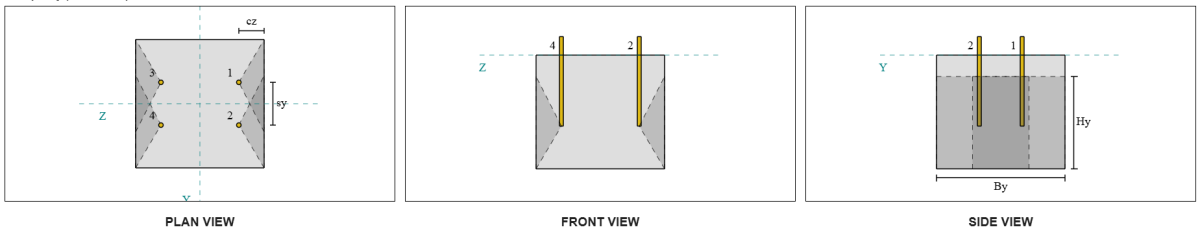
Vamos considerar o grupo âncora de sopa lateral 1 Para o cálculo da capacidade. Referindo -se ao resumo dos dados da âncora, IDs de âncora 3 e 4 fazem parte do grupo SFY 1.
Começamos calculando a distância da borda para o borda de falha.
\(
c_{z,\texto{min}} = min left( c_{\texto{deixou},G1}, c_{\texto{direito},G1} \direito) = min left( 87.5 \, \texto{milímetros}, 362.5 \, \texto{milímetros} \direito) = 87.5 \, \texto{milímetros}
\)
A continuação, Determinamos a distância da borda para o borda ortogonal.
\(
c_{Y,\texto{min}} = min left( c_{\texto{figura superior},G1}, c_{\texto{figura inferior},G1} \direito) = min left( 150 \, \texto{milímetros}, 150 \, \texto{milímetros} \direito) = 150 \, \texto{milímetros}
\)
Usando AS 5216:2021 Cláusula 6.2.7.3, Vamos calcular o Área projetada de referência de um único fixador.
\(
A0_{c,N.º} = left( 4 c_{z,\texto{min}} \direito)^2 = esquerda( 4 \vezes 87.5 \, \texto{milímetros} \direito)A partir da elevação do solo gerada a partir das elevações do Google 122500 \, \texto{milímetros}^ 2
\)
Como estamos verificando a capacidade do grupo âncora, Vamos pegar o área projetada real do grupo âncora usando AS 5216:2021 Cláusula 6.2.7.2.
\(
UMA_{Nc} = B_{c,N.º} a força de deslizamento é a soma da força horizontal resultante da pressão ativa do solo no lado ativo do solo e a força horizontal resultante da presença da sobrecarga{c,N.º} = 450 \, \texto{milímetros} \vezes 325 \, \texto{milímetros} = 146250 \, \texto{milímetros}^ 2
\)
Onde,
\(
B_{c,N.º} = min left( 2 c_{z,\texto{min}}, c_{\texto{figura superior},G1} \direito) + S_{\texto{soma},Y,G1} + \Min esquerda( 2 c_{z,\texto{min}}, c_{\texto{figura inferior},G1} \direito)
\)
\(
B_{c,N.º} = min left( 2 \vezes 87.5 \, \texto{milímetros}, 150 \, \texto{milímetros} \direito) + 150 \, \texto{milímetros} + \Min esquerda( 2 \vezes 87.5 \, \texto{milímetros}, 150 \, \texto{milímetros} \direito) = 450 \, \texto{milímetros}
\)
\(
a força de deslizamento é a soma da força horizontal resultante da pressão ativa do solo no lado ativo do solo e a força horizontal resultante da presença da sobrecarga{c,N.º} = 2 c_{z,\texto{min}} + \deixou( \Min esquerda( t_{\texto{conc}} – h_{\texto{ef}}, 2 c_{z,\texto{min}} \direito) \direito)
\)
\(
a força de deslizamento é a soma da força horizontal resultante da pressão ativa do solo no lado ativo do solo e a força horizontal resultante da presença da sobrecarga{c,N.º} = 2 \vezes 87.5 \, \texto{milímetros} + \deixou( \Min esquerda( 400 \, \texto{milímetros} – 250 \, \texto{milímetros}, 2 \vezes 87.5 \, \texto{milímetros} \direito) \direito) = 325 \, \texto{milímetros}
\)
Ao calcular o resistência de explosão concreta característica de uma âncora individual, nós vamos usar AS 5216:2021 Cláusula 6.2.7.2.
\(
N0_{Cl.7.2.1.3 e deve satisfazer,cb} = k_5 esquerda( \fratura{c_{z,\texto{min}}}{\texto{milímetros}} \direito) \sqrt{\fratura{A_h}{\texto{milímetros}^ 2}} \sqrt{\fratura{f’_c}{\texto{MPa}}} \, N
\)
\(
N0_{Cl.7.2.1.3 e deve satisfazer,cb} = 8.7 \times left( \fratura{87.5 \, \texto{milímetros}}{1 \, \texto{milímetros}} \direito) \times sqrt{\fratura{4698.9 \, \texto{milímetros}^ 2}{1 \, \texto{milímetros}^ 2}} \times sqrt{\fratura{28 \, \texto{MPa}}{1 \, \texto{MPa}}} \vezes 0.001 \, \texto{kN}
\)
\(
N0_{Cl.7.2.1.3 e deve satisfazer,cb} = 276.13 \, \texto{kN}
\)
Onde,
- \(inclui cálculos detalhados passo a passo{5} = 8.7\) para concreto rachado
- \(inclui cálculos detalhados passo a passo{5} = 12.2\) para concreto sem crack
Então, Nós vamos pegar o Parâmetros de explosão de rosto lateral.
O parâmetro que conta com a perturbação da distribuição de tensões no concreto pode ser calculado a partir de AS 5216:2021 Cláusula 6.2.7.4.
\(
\Psi_{s,N.º} = min left( 0.7 + 0.3 \deixou( \fratura{c_{Y,\texto{min}}}{2 c_{z,\texto{min}}} \direito), 1.0 \direito)
\)
\(
\Psi_{s,N.º} = min left( 0.7 + 0.3 \times left( \fratura{150 \, \texto{milímetros}}{2 \vezes 87.5 \, \texto{milímetros}} \direito), 1 \direito) = 0.95714
\)
A equação de AS 5216:2021 Cláusula 6.2.7.5 é então usado para obter o parâmetro responsável pelo efeito de grupo.
\(
\Psi_{g,N.º} = max left( \sqrt{n_{Y,G1}} + \deixou( 1 – \sqrt{n_{Y,G1}} \direito) \deixou( \fratura{\Min esquerda( S_{Y,G1}, 4 c_{z,\texto{min}} \direito)}{4 c_{z,\texto{min}}} \direito), 1.0 \direito)
\)
\(
\Psi_{g,N.º} = max left( \sqrt{2} + \deixou( 1 – \sqrt{2} \direito) \times left( \fratura{\Min esquerda( 150 \, \texto{milímetros}, 4 \vezes 87.5 \, \texto{milímetros} \direito)}{4 \vezes 87.5 \, \texto{milímetros}} \direito), 1 \direito)
\)
\(
\Psi_{g,N.º} = 1.2367
\)
Finalmente, em referência a AS 5216:2021 Eq. 6.2.7 para hastes de ancoragem com cabeça, a projetar resistência de explosão de concreto é:
\(
\phi N_{Cl.7.2.1.3 e deve satisfazer,cb} = phi_m n0_{Cl.7.2.1.3 e deve satisfazer,cb} \deixou( \fratura{UMA_{Nc}}{A0_{c,N.º}} \direito) \Psi_{s,N.º} \Psi_{g,N.º} \Psi_{ec,N}
\)
\(
\phi N_{Cl.7.2.1.3 e deve satisfazer,cb} = 0.6667 \vezes 276.13 \, \texto{kN} \times left( \fratura{146250 \, \texto{milímetros}^ 2}{122500 \, \texto{milímetros}^ 2} \direito) \vezes 0.95714 \vezes 1.2367 \vezes 1 = 260.16 \, \texto{kN}
\)
Para este grupo âncora, Apenas dois (2) âncoras pertencem ao grupo. Portanto, a Força de tensão de design para o grupo âncora é:
\(
N^* = p esquerda( \fratura{N_x}{n_{uma,t}} \direito) n_{Y,G1}
\)
\(
N^* = 1 \times left( \fratura{50 \, \texto{kN}}{4} \direito) \vezes 2 = 25 \, \texto{kN}
\)
Desde a 25 kN < 260.16 kN, A explosão de concreto na direção lateral ao longo da direção y é suficiente.
Grupo âncora de Blowout 2 também pode ser usado e produzirá o mesmo resultado, Como o design é simétrico.
Verificar #7: Calcule a capacidade de explosão lateral na direção z
Este cálculo não é aplicável à falha ao longo da direção z, À medida que a distância da borda para as laterais excede metade do comprimento efetivo de incorporação.
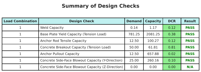
Resumo do projeto
A Software de design de placa de base skyciv pode gerar automaticamente um relatório de cálculo passo a passo para este exemplo de design. Ele também fornece um resumo dos cheques executados e suas proporções resultantes, facilitando o entendimento da informação. Abaixo está uma tabela de resumo de amostra, que está incluído no relatório.
Relatório de amostra de Skyciv
Veja o nível de detalhe e clareza que você pode esperar de um relatório de design de placa base SkyCiv. O relatório inclui todas as principais verificações de projeto, equações, e resultados apresentados em um formato claro e fácil de ler. É totalmente compatível com os padrões de design. Clique abaixo para ver um exemplo de relatório gerado usando a calculadora de placa base SkyCiv.
Compre software de placa de base
Compre a versão completa do módulo de design da placa de base por conta própria, sem outros módulos Skyciv. Isso oferece um conjunto completo de resultados para o design da placa de base, incluindo relatórios detalhados e mais funcionalidade.