Exemplo de design da placa de base usando AISC 360-22 e ACI 318-19
Declaração de problemas
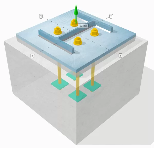
Determine se a conexão de placa coluna para base projetada é suficiente para uma carga de tensão de 20 kip.
Dados dados
Coluna:
Seção de coluna: W12X53
Área da coluna: 15.6 no2
Material da coluna: A992
Placa Base:
Dimensões da placa de base: 18 em x 18 no
Espessura da placa de base: 3/4 no
Material da placa de base: A36
Grout:
Espessura do rejunte: 1 no
Concreto:
Dimensões concretas: 22 em x 22 no
Espessura do concreto: 15 no
Material concreto: 4000 psi
Rachado ou sem crack: Rachado
Âncoras:
Diâmetro da âncora: 3/4 no
Comprimento eficaz de incorporação: 12 no
Largura da placa incorporada: 3 no
Espessura da placa incorporada: 1/4 no
Ancora Offset Distância da face da Web da coluna: 2.8275 no
Soldas:
Tamanho da solda: 1/4 no
Classificação de metal de enchimento: E70XX
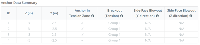
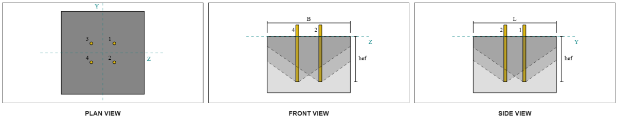
Dados de âncora (a partir de Calculadora Skyciv):
Modelo na ferramenta gratuita SkyCiv
Modele o design da placa de base acima usando nossa ferramenta online gratuita hoje mesmo! Não é necessária inscrição.
Definições
Caminho de carga:
Quando uma placa de base é submetida a elevada (tração) forças, Essas forças são transferidas para as hastes de ancoragem, que por sua vez induzem momentos de flexão na placa de base. A ação de flexão pode ser visualizada como Cantilever dobrando ocorrendo ao redor dos flanges ou da seção da coluna, dependendo de onde as âncoras estão posicionadas.
No Software de design de placa de base SkyCiv, apenas âncoras localizadas dentro do zona de tensão âncora são considerados eficazes para resistir à elevação. Esta zona normalmente inclui áreas próximas aos flanges ou web da coluna. Âncoras fora desta zona não contribuem para a resistência da tensão e são excluídas dos cálculos de elevação.
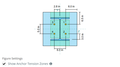
Para determinar a área efetiva da placa de base que resiste, uma 45-dispersão de grau é assumido a partir da linha central de cada haste de ancoragem em direção à face da coluna. Esta dispersão define o Comprimento eficaz da solda e ajuda a estabelecer o largura de flexão eficaz da placa.
A suposição simplifica a análise da placa de base, aproximando -se de como a força de elevação se espalha pela placa.
Grupos de âncora:
A Software de design de placa de base SkyCiv inclui um recurso intuitivo que identifica quais âncoras fazem parte de um grupo âncora para avaliar fuga de concreto e Sid concretoBlowout de e-face falhas.
A grupo âncora consiste em múltiplas âncoras com profundidades de incorporação eficazes semelhantes e espaçamento, e estão próximos o suficiente para que seu As áreas de resistência projetadas se sobrepõem. Quando as âncoras são agrupadas, Suas capacidades são combinadas para resistir à força de tensão total aplicada ao grupo.
Âncoras que não atendem aos critérios de agrupamento são tratadas como âncoras únicas. Nesse caso, Somente a força de tensão na âncora individual é verificada contra sua própria área de resistência efetiva.
Cálculos passo a passo
Verificar #1: Calcule a capacidade de solda
Aplicando Cargas Sísmicas, Precisamos calcular a carga por âncora e o comprimento efetivo da solda por âncora. O comprimento efetivo da solda é determinado pelo menor comprimento a partir do 45° Dispersão, restringido pelo comprimento real da solda e espaçamento âncora.
Para este cálculo, âncoras são classificadas como âncoras finais ou âncoras intermediárias. As âncoras finais estão localizadas nas extremidades de uma fileira ou coluna de âncoras, enquanto âncoras intermediárias estão posicionadas entre eles. O método de cálculo difere para cada um e depende da geometria da coluna. Neste exemplo, Existem duas âncoras ao longo da web, e ambos são classificados como âncoras finais.
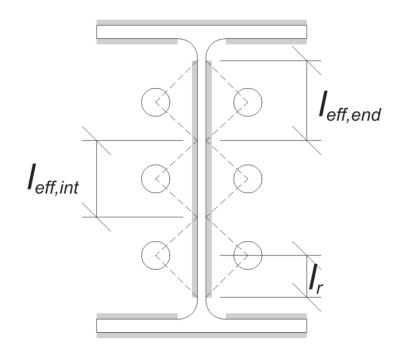
Para âncoras finais, O comprimento efetivo da solda é limitado pela distância disponível da linha central da âncora até o filé da coluna. A dispersão de 45 ° não deve se estender além desse limite.
\(
l_r = frac{d_{col} – 2t_f – 2r_{col} – S_(n_{uma,lado} – 1)}{2} = frac{12.1 \, \texto{no} – 2 \vezes 0.575 \, \texto{no} – 2 \vezes 0.605 \, \texto{no} – 5 \, \texto{no} \vezes (2 – 1)}{2} = 2.37 \, \texto{no}
\)
No lado interno, O comprimento efetivo é limitado pela metade do espaçamento âncora. O comprimento efetivo total da solda para a âncora final é a soma dos comprimentos externa e interna.
\(
eu_{ef,fim} = min(fazer, 0.5S_) + \min(fazer, l_r)
\)
\(
eu_{ef,fim} = min(2.8275 \, \texto{no}, 0.5 \vezes 5 \, \texto{no}) + \min(2.8275 \, \texto{no}, 2.37 \, \texto{no}) = 4.87 \, \texto{no}
\)
Para este exemplo, a Comprimento final eficaz da solda Para a âncora da web é tomada como a duração efetiva da âncora final.
\(
eu_{ef} = L_{ef,fim} = 4.87 \, \texto{no}
\)
A continuação, Vamos calcular o carga por âncora. Para um determinado conjunto de quatro (4) âncoras, A carga por âncora é:
\(
T_{você,âncora} = frac{N_x}{n_{uma,t}} = frac{20 \, \texto{kip}}{4} = 5 \, \texto{kip}
\)
Usando o comprimento efetivo calculado da solda, agora podemos determinar o Força necessária por unidade de comprimento na solda.
\(
r_u = frac{T_{você,âncora}}{eu_{ef}} = frac{5 \, \texto{kip}}{4.87 \, \texto{no}} = 1.0267 \, \texto{kip/in}
\)
Agora, nós vamos usar AISC 360-22, Capítulo J2.4 Para calcular a força do projeto da solda de filete.
Como a carga aplicada é uma tensão puramente axial, o ângulo \(\Theta ) é tomado como 90 °, e o coeficiente de força direcional KDS é calculado de acordo com AISC 360-22 Eq. J2-5.
\(
inclui cálculos detalhados passo a passo{ds} = 1.0 + 0.5(\sem(\theta))^{1.5} = 1 + 0.5 \vezes (\sem(1.5708))^{1.5} = 1.5
\)
Finalmente, nós vamos aplicar AISC 360-22 Eq. J2-4 Para determinar o Força de projeto da solda de filete por unidade de comprimento.
\(
\Phi r_n = phi 0.6 F_{Exx} E_{C,rede} inclui cálculos detalhados passo a passo{ds} = 0.75 \vezes 0.6 \vezes 70 \, \texto{ksi} \vezes 0.177 \, \texto{no} \vezes 1.5 = 8.3633 \, \texto{kip/in}
\)
Desde a 1.0267 KPI < 8.3633 KPI, A capacidade de solda é suficiente.
Verificar #2: Calcule a capacidade de rendimento flexural da placa de base devido à carga de tensão
Usando tele carrega por âncora e o oDistância do centro do centro da âncora para a face da coluna (servindo como excentricidade de carga), O momento aplicado à placa de base pode ser calculado usando um em balanço suposição.
\(
M_u = t_{você,\texto{âncora}} e = 5 \, \texto{kip} \vezes 2.8275 \, \texto{no} = 14.137 \, \texto{kip} \CDOT Text{no}
\)
A continuação, usando o calculard Comprimento eficaz da solda param a verificação anterior como a largura de flexão, Podemos calcular o SkyCiv Foundation é um módulo de projeto para o projeto de sapatas articuladas a partir das cargas da superestrutura da placa de base usando AISC 360-22, Equação 2-1:
\(
\não -m_n = phi f_{Y,\texto{pb}} Z_{\texto{ef}} = 0.9 \vezes 36 \, \texto{ksi} \vezes 0.68484 \, \texto{no}^3 = 22.189 \, \texto{kip} \CDOT Text{no}
\)
Onde,
\(
Z_{\texto{ef}} = frac{eu_{\texto{ef}} (t_{\texto{pb}})^ 2}{4} = frac{4.87 \, \texto{no} \vezes (0.75 \, \texto{no})^ 2}{4} = 0.68484 \, \texto{no}^ 3
\)
Desde a 14.137 frango em < 22.189 frango em, A capacidade de rendimento flexural da placa de base é suficiente.
Verificar #3: Calcule a capacidade de tração à haste de ancoragem
Para avaliar a capacidade de tração da haste de ancoragem, nós vamos usar ACI 318-19 Equação 17.6.1.2.
Primeiro, Nós determinamos o resistência à tração especificada do aço âncora. Este é o menor valor permitido por ACI 318-19 Cláusula 17.6.1.2, com referência às propriedades do material em AISC 360-22 Tabela J3.2.
\(
f_{\texto{uta}} = min left( 0.75 F_{você,\texto{anc}}, 1.9 F_{Y,\texto{anc}}, 125 \direito) = min left( 0.75 \vezes 120 \, \texto{ksi}, 1.9 \vezes 92 \, \texto{ksi}, 125.00 \, \texto{ksi} \direito) = 90 \, \texto{ksi}
\)
A continuação, nós calculamos o Área transversal eficaz da haste de ancoragem. Isso é baseado em ACI 318-19 Cláusula de comentários R17.6.1.2, que explica a geometria de threads. O número de fios por polegada é retirado de ASME B1.1-2019 Tabela 1.
\(
UMA_{eu sei,N} = frac{\pi}{4} \deixou( d_a – \fratura{0.9743}{n_t} \direito)^2 = frac{\pi}{4} \times left( 0.75 \, \texto{no} – \fratura{0.9743}{10 \, \texto{no}^{-1}} \direito)A partir da elevação do solo gerada a partir das elevações do Google 0.33446 \, \texto{no}^ 2
\)
Com esses valores, nós aplicamos ACI 318-19 Equação 17.6.1.2 Para calcular o projetar força de tração da haste de ancoragem.
\(
\phi N_{para} = phi A_{eu sei,N} f_{\texto{uta}} = 0.75 \vezes 0.33446 \, \texto{no}^2 Times 90 \, \texto{ksi} = 22.576 \, \texto{kip}
\)
Lembre -se do calculado anteriormente carga de tensão por âncora:
\(
N_{fazer} = frac{N_x}{n_{uma,t}} = frac{20 \, \texto{kip}}{4} = 5 \, \texto{kip}
\)
Desde a 5 kip < 22.576 kip, A capacidade de tração da haste da ancoragem é suficiente.
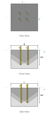
Verificar #4: Calcule a capacidade de fuga de concreto na tensão
Antes de calcular a capacidade de fuga, devemos primeiro determinar se o membro se qualifica como um membro estreito. De acordo com ACI 318-19 Cláusula 17.6.2.1.2, O membro atende aos critérios para um membro estreito. Portanto, Um comprimento efetivo de incorporação modificado deve ser usado nos cálculos.
É determinado que o comprimento efetivo de incorporação modificado, H'ef, do grupo âncora é:
\(
h'_{\texto{ef}} = 5.667 \, \texto{no}
\)
Usando ACI 318-19 Cláusula 17.6.2, nós calculamos o Área máxima de cone de concreto projetado para uma única âncora, com base no comprimento efetivo modificado de incorporação.
\(
UMA_{N_{co}} = 9 \deixou( h'_{ef,G1} \direito)A partir da elevação do solo gerada a partir das elevações do Google 9 \times left( 5.6667 \, \texto{no} \direito)A partir da elevação do solo gerada a partir das elevações do Google 289 \, \texto{no}^ 2
\)
similarmente, Usamos o comprimento efetivo modificado de incorporação para calcular o Área de cone de concreto projetada real do grupo âncora.
\(
UMA_{N_c} = min left( n_{uma,G1} UMA_{N_{co}}, EU_{N_c} B_{N_c} \direito) = min left( 4 \vezes 289 \, \texto{no}^ 2, 22 \, \texto{no} \vezes 22 \, \texto{no} \direito) = 484 \, \texto{no}^ 2
\)
Onde,
\(
EU_{N_c} = min left( c_{\texto{deixou},G1}, 1.5 h'_{\texto{ef},G1} \direito)
+ \deixou( \Min esquerda( S_{\texto{soma},z,G1}, 3 h'_{\texto{ef},G1} \deixou( n_{z,G1} – 1 \direito) \direito) \direito)
+ \Min esquerda( c_{\texto{direito},G1}, 1.5 h'_{\texto{ef},G1} \direito)
\)
\(
EU_{N_c} = min left( 8 \, \texto{no}, 1.5 \vezes 5.6667 \, \texto{no} \direito)
+ \deixou( \Min esquerda( 6 \, \texto{no}, 3 \vezes 5.6667 \, \texto{no} \times left( 2 – 1 \direito) \direito) \direito)
+ \Min esquerda( 8 \, \texto{no}, 1.5 \vezes 5.6667 \, \texto{no} \direito)
\)
\(
EU_{N_c} = 22 \, \texto{no}
\)
\(
B_{N_c} = min left( c_{\texto{figura superior},G1}, 1.5 h'_{\texto{ef},G1} \direito)
+ \deixou( \Min esquerda( S_{\texto{soma},Y,G1}, 3 h'_{\texto{ef},G1} \deixou( n_{Y,G1} – 1 \direito) \direito) \direito)
+ \Min esquerda( c_{\texto{figura inferior},G1}, 1.5 h'_{\texto{ef},G1} \direito)
\)
\(
B_{N_c} = min left( 8.5 \, \texto{no}, 1.5 \vezes 5.6667 \, \texto{no} \direito)
+ \deixou( \Min esquerda( 5 \, \texto{no}, 3 \vezes 5.6667 \, \texto{no} \times left( 2 – 1 \direito) \direito) \direito)
+ \Min esquerda( 8.5 \, \texto{no}, 1.5 \vezes 5.6667 \, \texto{no} \direito)
\)
\(
B_{N_c} = 22 \, \texto{no}
\)
A continuação, Nós avaliamos o Força básica de fuga de concreto de uma única âncora usando ACI 318-19 Cláusula 17.6.2.2.1
\(
N_b = k_c lambda_a sqrt{\fratura{f’_c}{\texto{psi}}} \deixou( \fratura{h'_{\texto{ef},G1}}{\texto{no}} \direito)^{1.5} \, \texto{Detalhes e parâmetros do modelo}
\)
\(
N_b = 24 \vezes 1 \times sqrt{\fratura{4 \, \texto{ksi}}{0.001 \, \texto{ksi}}} \times left( \fratura{5.6667 \, \texto{no}}{1 \, \texto{no}} \direito)^{1.5} \vezes 0.001 \, \texto{kip} = 20.475 \, \texto{kip}
\)
Onde,
- \(inclui cálculos detalhados passo a passo{c} = 24\) para âncoras fundidas
- \(\lambda = 1.0 \) para concreto de peso normal
Agora, Avaliamos os efeitos da geometria calculando o fator de efeito de borda quanto pelo Fator de excentricidade.
A distância da borda mais curta do grupo âncora é determinada como:
\(
c_{uma,\texto{min}} = min left( c_{\texto{deixou},G1}, c_{\texto{direito},G1}, c_{\texto{figura superior},G1}, c_{\texto{figura inferior},G1} \direito)
= min left( 8 \, \texto{no}, 8 \, \texto{no}, 8.5 \, \texto{no}, 8.5 \, \texto{no} \direito) = 8 \, \texto{no}
\)
De acordo com ACI 318-19 Cláusula 17.6.2.4.1, a fuga fator de efeito de borda é:
\(
\Psi_{ed,N} = min left( 1.0, 0.7 + 0.3 \deixou( \fratura{c_{uma,\texto{min}}}{1.5 h'_{\texto{ef},G1}} \direito) \direito)
= min left( 1, 0.7 + 0.3 \times left( \fratura{8 \, \texto{no}}{1.5 \vezes 5.6667 \, \texto{no}} \direito) \direito) = 0.98235
\)
Como a carga de tensão é aplicada no centróide do grupo âncora, A excentricidade é zero. Por isso, a Fator de excentricidade, Também da cláusula 17.6.2.4.1, é:
\(
\Psi_{ec,N} = min left( 1.0, \fratura{1}{1 + \fratura{2 e n}{3 h'_{\texto{ef},G1}}} \direito)
= min left( 1, \fratura{1}{1 + \fratura{2 \vezes 0}{3 \vezes 5.6667 \, \texto{no}}} \direito) = 1
\)
Além disso, ambos fator de rachadura quanto pelo fator de divisão são tomados como:
\(
\Psi_{c,N} = 1
\)
\(
\Psi_{cp,N} = 1
\)
Então, Combinamos todos esses fatores e usamos ACI 318-19 Eq. 17.6.2.1b para avaliar o força de fuga de concreto do grupo âncora:
\(
\phi N_{cbg} = phi esquerda( \fratura{UMA_{N_c}}{UMA_{N_{co}}} \direito) \Psi_{ec,N} \Psi_{ed,N} \Psi_{c,N} \Psi_{cp,N} N_b
\)
\(
\phi N_{cbg} = 0.7 \times left( \fratura{484 \, \texto{no}^ 2}{289 \, \texto{no}^ 2} \direito) \vezes 1 \vezes 0.98235 \vezes 1 \vezes 1 \vezes 20.475 \, \texto{kip} = 23.58 \, \texto{kip}
\)
A carga total de tensão aplicada No grupo âncora está o produto da carga de âncora individual e o número de âncoras:
\(
N_{fazer} = left( \fratura{N_x}{n_{uma,t}} \direito) n_{uma,G1} = left( \fratura{20 \, \texto{kip}}{4} \direito) \vezes 4 = 20 \, \texto{kip}
\)
Desde a 20 kips < 23.58 kips, A capacidade de fuga de concreto é suficiente.
Verificar #5: Calcule a capacidade de extração de âncora
A capacidade de extração de uma âncora é governada pela resistência em sua extremidade incorporada. Aplicando Cargas Sísmicas, Calculamos a área de rolamento da placa incorporada, que é a área líquida após subtrair a área ocupada pela haste da ancoragem.
Para uma placa incorporada retangular, a Área de rolamentos é calculado como:
\(
UMA_{brg} = left( \deixou( b_{incorporar _plate} \direito)^2 certo) – UMA_{haste} = left( \deixou( 3 \, \texto{no} \direito)^2 certo) – 0.44179 \, \texto{no}A partir da elevação do solo gerada a partir das elevações do Google 8.5582 \, \texto{no}^ 2
\)
Onde,
\(
UMA_{haste} = frac{\pi}{4} \deixou( d_a certo)^2 = frac{\pi}{4} \times left( 0.75 \, \texto{no} \direito)A partir da elevação do solo gerada a partir das elevações do Google 0.44179 \, \texto{no}^ 2
\)
A continuação, Nós determinamos o Força básica de extração de âncora usando ACI 318-19 Equação 17.6.3.2.2a.
\(
N_b = 8 UMA_{brg} \deixou( f'_C certo) = 8 \vezes 8.5582 \, \texto{no}^2 Times Esquerda( 4 \, \texto{ksi} \direito) = 273.86 \, \texto{kip}
\)
Em seguida, aplicamos o fator de resistência apropriado e fator de rachaduras de puxar:
- Pra rachado concreto, \(\Psi_{cp} = 1.0\)
- Pra não empurrado concreto, \(\Psi_{cp} = 1.4\)
Usando estes, nós calculamos o projetar força de retirada de âncora na tensão por ACI 318-19 Equação 17.6.3.1.
\(
\phi N_{pn} = Phi psi_{c,p} N_b = 0.7 \vezes 1 \vezes 273.86 \, \texto{kip} = 191.7 \, \texto{kip}
\)
Lembre -se do calculado anteriormente carga de tensão por âncora:
\(
N_{fazer} = frac{N_x}{n_{uma,t}} = frac{20 \, \texto{kip}}{4} = 5 \, \texto{kip}
\)
Desde a 5 kips < 191.7 kips, A capacidade de extração de âncora é suficiente.
Verificar #6: Calcule a capacidade de flexão da placa incorporada
Esta é uma verificação suplementar realizada usando o Software de design de placa de base skyciv Para verificar se a placa incorporada tem capacidade de flexão suficiente e não cederá sob as cargas de retirada aplicadas.
Primeiro, Determinamos o comprimento do grátis (não suportado) final da placa incorporada, medido a partir da borda do apoio à face da haste.
\(
b’ = frac{b_{incorporar _plate} – d_a}{2} = frac{3 \, \texto{no} – 0.75 \, \texto{no}}{2} = 1.125 \, \texto{no}
\)
A continuação, nós calculamos o momentos de flexão induzido pela pressão uniforme do rolamento. Esta pressão representa a força transferida da ação de retirada da âncora para a placa incorporada.
\(
m_f = frac{\deixou( \fratura{T_a}{UMA_{brg}} \direito) \deixou( b’ \direito)^ 2}{2} = frac{\deixou( \fratura{5 \, \texto{kip}}{8.5582 \, \texto{no}^ 2} \direito) \times left( 1.125 \, \texto{no} \direito)^ 2}{2} = 0.36971 \, \texto{kip}
\)
Finalmente, usando o momento calculado e as propriedades do material dadas, Vamos determinar o espessura mínima de placa necessária para resistir rendimento flexural.
\(
t_{min} = sqrt{\fratura{4 m_f}{\Phi f_{sim}}} = sqrt{\fratura{4 \vezes 0.36971 \, \texto{kip}}{0.9 \vezes 36 \, \texto{ksi}}} = 0.21364 \, \texto{no}
\)
Lembre -se de espessura real da placa incorporada:
\(
t_{real} = t_{incorporar _plate} = 0.25 \, \texto{no}
\)
Desde a 0.21364 no < 0.25 no, A capacidade de flexão de placas incorporada é suficiente.
Verificar #7: Calcule a capacidade de explosão lateral na direção y
Este cálculo não é aplicável a este exemplo, Como as condições especificadas em ACI 318-19 Cláusula 17.6.4 não são atendidos. Portanto, A falha de explosão de rosto lateral ao longo da direção y não ocorrerá.
Verificar #8: Calcule a capacidade de explosão lateral na direção z
Este cálculo não é aplicável a este exemplo, Como as condições especificadas em ACI 318-19 Cláusula 17.6.4 não são atendidos. Portanto, A falha de explosão lateral ao longo da direção z não ocorrerá.
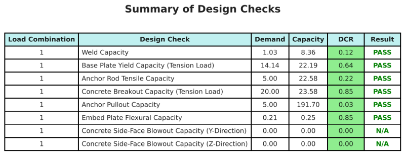
Resumo do projeto
A Software de design de placa de base skyciv pode gerar automaticamente um relatório de cálculo passo a passo para este exemplo de design. Ele também fornece um resumo dos cheques executados e suas proporções resultantes, facilitando o entendimento da informação. Abaixo está uma tabela de resumo de amostra, que está incluído no relatório.
Relatório de amostra de Skyciv
Veja o nível de detalhe e clareza que você pode esperar de um relatório de design de placa base SkyCiv. O relatório inclui todas as principais verificações de projeto, equações, e resultados apresentados em um formato claro e fácil de ler. É totalmente compatível com os padrões de design. Clique abaixo para ver um exemplo de relatório gerado usando a calculadora de placa base SkyCiv.
Compre software de placa de base
Compre a versão completa do módulo de design da placa de base por conta própria, sem outros módulos Skyciv. Isso oferece um conjunto completo de resultados para o design da placa de base, incluindo relatórios detalhados e mais funcionalidade.