Overzicht
IN 1993-1-1: Ontwerp van staalconstructies (Eurocode 3) schetst ontwerprichtlijnen voor constructieve stalen elementen voor gebruik in gebouwen met behulp van de grenstoestandmethode. Het ontwerp van de grenstoestand omvat het vergelijken van de berekende ontwerpbelastingen met de verminderde sectie- en staafcapaciteiten. Deze factoren zijn bedoeld om rekening te houden met de variabiliteit in beladingsomstandigheden en materiaaleigenschappen. Voor de ultieme grenstoestand (ULS) ontwerp om tevreden te zijn, de volgende relatie moet waar zijn:
\(ULS \;Factor * Belasting ≤ Reductie \;Factor * Capaciteit)
Deze ontwerpgids schetst de procedure voor het ontwerpen van een constructiestaalelement in overeenstemming met EN 1993-1-1 de ... gebruiken IN 1993-1-1 Ontwerp van stalen leden module.
Let op onze Eurocode 3 Demo staalontwerp
Inhoud
Materiaaleigenschappen
Fabricage
IN 1993-1-1 biedt ontwerprichtlijnen voor vier soorten constructiestaalfabricage:
- Warmgewalste secties: Warmgewalste profielen worden vervaardigd door stalen knuppels door een molen te verwarmen en te walsen om de gewenste vorm te verkrijgen. Voorbeelden hiervan zijn UB/UC/UBP I-secties, T-secties, Kanalen en hoeksecties.
- Gelaste secties: Gelast (of verzonnen) secties bestaan uit verschillende warmgewalste vlakke platen die in de lengterichting aan elkaar zijn gelast om een stalen vorm te vormen. Op maat gemaakte secties worden doorgaans gelast.
- Heet afgewerkte secties: Heet afgewerkte profielen worden geproduceerd door staal vóór het walsen te verwarmen tot boven de herkristallisatietemperatuur om de sterkte van het eindproduct te verbeteren. Deze profielen zijn vrijwel altijd constructieve holle profielen (RHS/SHS/CHS).
- Koudgevormde secties: Koudgevormde profielen worden vervaardigd door stalen knuppels bij kamertemperatuur door een molen te persen. Koudvervormen kan worden gebruikt om structurele holle profielen en dunnere open profielen te produceren. Opmerking NL 1993-1-1 geeft alleen richtlijnen voor holle koudgevormde profielen.
Staalkwaliteit
Europa en het Verenigd Koninkrijk kennen talrijke staalsoorten (sterke punten) die gebruikt kunnen worden voor ontwerp conform EN 1993-1-1. Er zijn verschillende Europese materiaalnormen voor verschillende soorten staalproductie:
- IN 10025: Warmgewalste producten.
- IN 100210: Warm afgewerkte structurele holle profielen.
- IN 10219: Koudgevormde gelaste structurele holle profielen.
Warmgewalste secties (IN 10025)
De gebruikelijke beschikbaarheid van kwaliteiten en indicatieve vloeisterktes voor warmgewalste staalvormen worden hieronder beschreven:
Minimale vloeigrens (MPa) |
|||||||||
|---|---|---|---|---|---|---|---|---|---|
| Cijfer | ≤16mm | 16-40mm | 40-63mm | 63-80mm | 80-100mm | 100-150mm | 150-200mm | 200-250mm | 250-400mm |
| S 235 | 235 | 225 | 215 | 215 | 215 | 195 | 185 | 175 | 165 |
| S 275 | 275 | 265 | 255 | 245 | 235 | 225 | 215 | 205 | 195 |
| S 355 | 355 | 345 | 335 | 325 | 315 | 295 | 285 | 275 | 265 |
| S 460 | 460 | 440 | 420 | 400 | 390 | 390 | – | – | – |
Minimale treksterkte (MPa) |
||||||
|---|---|---|---|---|---|---|
| Cijfer | ≤3 mm | 3-100mm | 100-150mm | 150-250mm | 250-400mm | |
| S 235 | 360 | 350 | 350 | 340 | 330 | |
| S 275 | 430 | 410 | 400 | 380 | 380 | |
| S 355 | 510 | 470 | 450 | 450 | 450 | |
| S 460 | – | 550 | 530 | – | – | |
Heet afgewerkte structurele holle secties (IN 100210)
De gebruikelijke beschikbaarheid van kwaliteiten en indicatieve vloeisterktes voor warm afgewerkte structurele holle profielen worden hieronder uiteengezet:
Minimale vloeigrens (MPa) |
||||||
|---|---|---|---|---|---|---|
| Cijfer | ≤16mm | 16-40mm | 40-63mm | 63-80mm | 80-100mm | 100-120mm |
| S 235 H. | 235 | 225 | 215 | 215 | 215 | 195 |
| S 275 H. | 275 | 265 | 255 | 245 | 235 | 225 |
| S 355 H. | 355 | 345 | 335 | 325 | 315 | 295 |
Minimale treksterkte (MPa) |
|||
|---|---|---|---|
| Cijfer | ≤3 mm | 3-100mm | 100-120mm |
| S 235 H. | 360 | 360 | 350 |
| S 275 H. | 430 | 410 | 400 |
| S 355 H. | 510 | 470 | 450 |
Opbrengst & Treksterkte
De vloeigrens van een materiaal is de spanningsgrens waarboven plastische vervorming zal optreden. De treksterkte is de maximale spanning die een materiaal kan verdragen voordat het bezwijkt / breekt uit elkaar. Opbrengst- en treksterkten van stalen profielen zijn afhankelijk van de staalkwaliteit en dikte. Normaal gesproken neemt de sterkte toe met de staalsoort, maar neemt af met een grotere staaldikte.
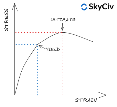
IN 1993-1-1 Tafel 3.1 biedt een vereenvoudigde aanpak voor het berekenen van de rek- en treksterkte van een sectie op basis van de kwaliteit en dikte. Een meer gedetailleerde materiaalsterkteberekening kan worden uitgevoerd door te verwijzen naar de materiaalrelevante materiaalnorm. De SkyCiv NL 1993-1-1 De Steel Member Design-module doet dat wel niet maken gebruik van deze vereenvoudiging en verwijzen in plaats daarvan naar de relevante materiaalnormen voor de berekening van de materiaalsterkte.
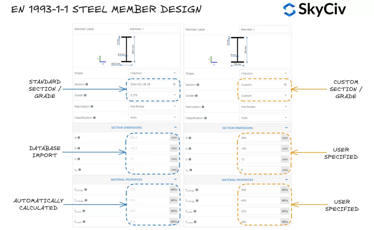
Een sectie selecteren in SkyCiv NL 1993-1-1 Ontwerp van stalen leden
De SkyCiv IN 1993-1-1 Ontwerp van stalen leden Met de tool kunnen gebruikers een standaard stalen sectie uit de SkyCiv-database selecteren of een volledig aangepaste sectie ontwerpen. Het programma berekent automatisch de vloeigrenswaarden voor de sectieflens en het lijf op basis van de geselecteerde staalsoort. Gebruikers kunnen indien nodig ook een aangepaste staalsoort gebruiken en de materiaaleigenschappen handmatig invoeren.
Sectieclassificatie
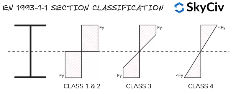
Sectieclassificatie is een systeem dat wordt gebruikt door EN 1993-1-1 om de gevoeligheid van een sectie voor lokaal knikken te identificeren voordat de volledige plastic capaciteit wordt bereikt. Grote, slanke vormen zijn doorgaans gevoeliger voor plaatselijk knikken dan kleine, gedrongen vormen. De SkyCiv IN 1993-1-1 Ontwerp van stalen leden tool berekent automatisch de classificatie van standaard en op maat gemaakte staalprofielen op basis van de toegepaste belastingsomstandigheden. Eurocode 3 heeft vier sectieclassificatiecategorieën:
- Klas 1: Secties die een plastisch scharnier kunnen vormen en hun plastische moment-/axiale weerstand kunnen ontwikkelen, dit betekent dat de gehele sectie zijn vloeigrens kan bereiken onder buiging en/of druk. Klas 1 secties hebben ook een hoge rotatiecapaciteit. Kunststof profieleigenschappen worden gebruikt bij capaciteitsberekeningen.
- Klas 2: Secties met de mogelijkheid om een plastic scharnier te vormen, maar hebben een beperkte rotatiecapaciteit. Eurocode 3 behandelt klasse 1 en Klasse 2 secties op dezelfde manier voor bijna alle capaciteitsberekeningen.
- Klas 3: Secties die vloeigrens kunnen bereiken in hun extreem samendrukkende vezel, maar plaatselijk knikken voordat plastische momentweerstand wordt bereikt. Eigenschappen van elastische secties worden gebruikt bij capaciteitsberekeningen.
- Klas 4: Lokaal knikken zal optreden voordat de vloeigrens in een deel/s van de sectie wordt bereikt. Bij capaciteitsberekeningen worden gereduceerde elastische sectie-eigenschappen gebruikt.
Notitie, Klas 4 secties omvatten extra complexiteit bij de berekening van sectie-eigenschappen / weerstand en worden niet behandeld in deze handleiding.
Compressie-elementen
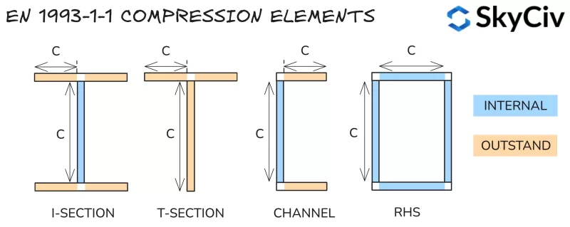
De sectieclassificatie wordt bepaald door een sectie op te delen in een reeks compressie-elementen en hun slankheid te berekenen (vrije lengte ten opzichte van de dikte). Elementen worden als een van beide geclassificeerd:
- Intern: Aan beide uiteinden beschermd tegen knikken – d.w.z. web van een I-sectie.
- Uitstekend: Alleen aan één uiteinde beveiligd tegen knikken – d.w.z. flens van een I-sectie.
De berekende slankheidswaarden worden vergeleken met Tabel 5.2 in EN 1993-1-1 om hun klasse te bepalen. De classificatie van de sectie wordt beschouwd als de minst gunstige classificatie van de compressie-elementen. Notitie, sectieclassificatie verandert afhankelijk van de krachten op de sectie (bijzonder variërende axiale kracht). Methoden voor het classificeren van elk type belasting worden hieronder samengevat.
Classificatieverhoudingen
Onderdelen die onderhevig zijn aan compressie
Elementen met pure compressie worden geclassificeerd op basis van hun slankheid, waarbij alleen gebruik wordt gemaakt van de onderstaande limieten.
| Klas | Interne onderdelen | Uitstekende onderdelen | |
| 1 | c / t ≤ 33ε | c / t ≤ 9ε | |
| 2 | c / t ≤ 38e | c / t ≤ 10ε | |
| 3 | c / t ≤ 42ε | c / t ≤ 14e | |
Waarbij:
\(ε = sqrt{\frac{235}{f_y}}\)
Onderdelen die onderhevig zijn aan buiging
Interne elementen bij puur buigen worden geclassificeerd op basis van hun slankheid, volgens de onderstaande limieten.
| Klas | Interne onderdelen | |
| 1 | c / t ≤ 72ε | |
| 2 | c / t ≤ 83e | |
| 3 | c / t ≤ 124e | |
Uitstaande elementen die onderhevig zijn aan pure buiging worden geclassificeerd op basis van de verhouding tussen druk- en trekspanning onder de waarde van het buigmoment, wat resulteert in een drukspanning die gelijk is aan de vloeispanning bij de uiterste vezel. De methode voor het berekenen van deze verhouding wordt beschreven in het onderstaande gedeelte.
Onderdelen die onderhevig zijn aan compressie & Buigen
Elementen die onderhevig zijn aan gecombineerde compressie en buiging worden geclassificeerd op basis van hun compressie / trekspanningsverdeling onder de toegepaste drukbelasting. Deze verhouding wordt weergegeven door het α-symbool voor de plastische spanningsverdeling en het ψ-symbool voor de elastische spanningsverdeling.
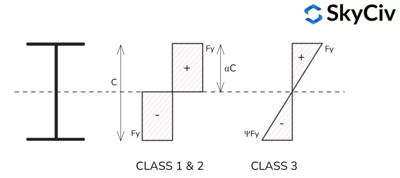
Plastische spanningsverdeling
Formules voor het berekenen van de plastische spanningsverhouding (een) voor verschillende vormprofielen vindt u hieronder.
I-sectie kunststof spanningsverdeling

T-sectie kunststof spanningsverdeling
Let op: de spanningsverdelingen op de kleine as voor T-secties zijn vergelijkbaar met die van een I-sectie.

Kanaal Kunststof sectie Spanningsverdeling
Merk op dat de spanningsverdelingen op de hoofdas voor T-secties vergelijkbaar zijn met die van een I-sectie.

RHS Plastische spanningsverdeling

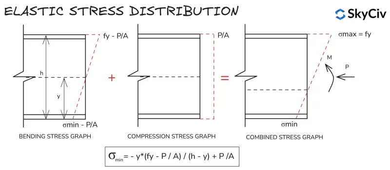
Elastische spanningsverdeling
Berekeningen voor de elastische spanningsverdeling zijn voor alle secties en vormen vergelijkbaar, vanwege de lineaire spanningsverdeling tussen de extreme vezels. De formule voor het berekenen van de minimale spanning in een sectie onder uitgeoefende druk en buiging wordt hieronder weergegeven.
Sectieclassificatie in SkyCiv NL 1993-1-1 Ontwerp van stalen leden
De SkyCiv EEN 1993-1-1 Ontwerp van stalen leden tool bepaalt automatisch de sectieclassificatie van standaard- en aangepaste secties op basis van het laden van gebruikersinvoer. Een voorbeelduitvoer voor een klasse S 275, 430x100x64 Kanaal met 20 kN compressiebelasting wordt hieronder gedetailleerd beschreven.
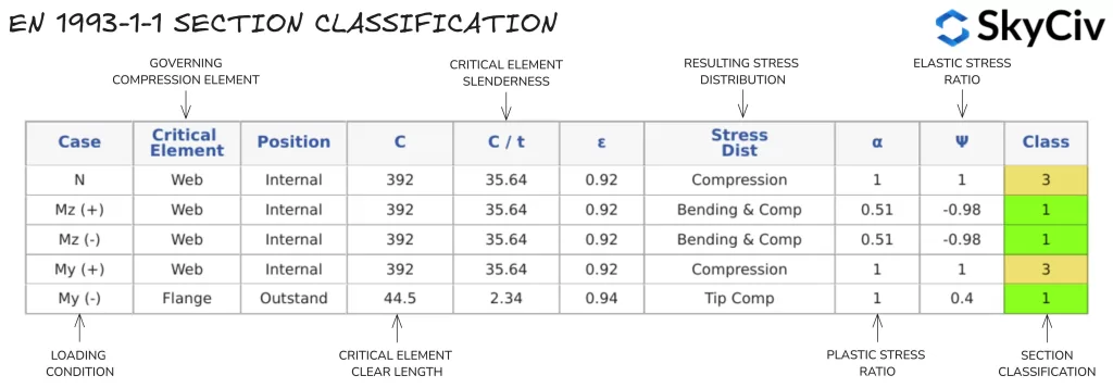
Er wordt één enkele sectieclassificatiewaarde gebruikt voor alle berekeningen op basis van de toegepaste axiale kracht en richting van het toegepaste buigmoment. Als op een staaf een buigmoment wordt toegepast rond beide assen, de meest conservatieve classificatie vanuit elke richting wordt aangenomen. Gebruikers kunnen ook de automatische berekening van sectieclassificatie overschrijven en handmatig een classificatie opgeven.
Notitie, Clausule 5.4.1(3) specificeert dat afzonderlijk symmetrische secties (zoals T-secties en kanalen) kunnen niet worden ontworpen met behulp van plastische analyse wanneer ze om hun niet-symmetrische as worden gebogen. Daarom worden secties van deze aard automatisch aan Klasse toegewezen 3.
Sectie weerstand
Buigen
Sectie Buigweerstand
Het buigmomentvermogen van de sectie wordt berekend met behulp van EN 1993-1-1 Clausule 6.2.5.
\(M_{c,Rd} = W*f_y/γ_{M0}\)
Waar W de plastic sectiemodulus is (WEN1993-1-1) voor Klasse 1 & 2 secties, of de elastische sectiemodulus (WHij) voor Klasse 3 secties, fj is de vloeispanning van het materiaal en γ is de gedeeltelijke veiligheidsreductiefactor.
De sectiemodulus van een vorm is een geometrische eigenschap die de buigweerstand van een vorm kwantificeert. De plastische sectiemodulus gaat ervan uit dat de gehele sectie onder buiging zijn vloeigrens bereikt. De plastische sectiemodulus van een sectie wordt als volgt berekend:
\(W_{EN1993-1-1} = A_{C} * j_{C} + EEN_{T} * j_{T} \)
Waar eenC en eenT zijn de gebieden aan weerszijden van de Plastic Neutrale As (PNA), en yc / jt zijn de afstand van de PNA tot het zwaartepunt van die gebieden. Notitie, de PNA-locatie is gelijk aan de geometrische zwaartepuntlocatie voor symmetrische vormen, maar zal dat wel doen niet gelijk aan de geometrische zwaartepuntlocatie voor asymmetrische vormen.
De elastische sectiemodulus gaat uit van de gehele sectie (vorm) blijft elastisch onder buiging, d.w.z. geen enkel deel van de sectie overschrijdt de vloeigrens (fj) van het materiaal. De elastische sectiemodulus van een sectie wordt als volgt berekend:
\(W_{Hij} = frac{I}{j}\)
Waarbij I het tweede oppervlaktemoment is en y het geometrische zwaartepunt van de vorm. Opmerking voor een asymmetrische vorm, de waarde van de elastische modulus die bij het ontwerp wordt gebruikt, is de kleinere waarde voor positieve en negatieve buiging rond die as.
Berekening van de buigweerstand van secties in SkyCiv EN 1993-1-1 Ontwerp van stalen leden
Zodra de betreffende Sectieclassificatie is berekend, de module berekent de buigmomentcapaciteit van de sectie (Mc) rond elke hoofdas. Resultaten voor hetzelfde 430x100x64-kanaal worden weergegeven in het onderstaande voorbeeld.

Schuintrekken
Sectie schuifweerstand
De schuifweerstand wordt berekend met behulp van EN 1993-1-1 Clausule 6.2.6. Capaciteitsberekeningen zijn afhankelijk van de sectieclassificatie van het stalen element. Capaciteit voor klasse 1 & 2 secties worden berekend op basis van de plastische schuifweerstand, terwijl voor Klasse een elastische schuifweerstand wordt gebruikt 3 & 4 secties.
De plastische schuifweerstand wordt berekend met behulp van de onderstaande formule:
\(V_{EN1993-1-1,Rd}=A_v * (f_y / \sqrt{3}) / C_{M0}\)
Waarbij Av het afschuifoppervlak van de sectie is in de richting van de uitgeoefende afschuifkracht. Voor de meeste secties is dit oppervlak gelijk aan het oppervlak van het lijf voor afschuiving in de hoofdasrichting, en het oppervlak van de flenzen voor de andere richting. Formules voor het berekenen van het afschuifoppervlak zijn te vinden in EN 1993-1-1 Clausule 6.2.6(3).
De elastische schuifweerstand wordt berekend met behulp van de onderstaande relatie, wat ervoor zorgt dat de schuifspanning op het kritische punt van de doorsnede kleiner is dan de vloeispanning.
\(T_{Ed}/(f_y / (\sqrt{3 * C_{M0}})) ≤ 1\)
De schuifspanning op dit kritische punt wordt als volgt berekend:
\(T_{Ed}=(V_{Ed} * S)/(I * t)\)
Waar VEd is de toegepaste schuifkracht, S is het eerste oppervlaktemoment, I is het sectiemoment van het oppervlak en t is de dikte op de kritische spanningslocatie.
De elastische schuifspanningsformule kan vervolgens zo worden ingericht dat deze een weerstandswaarde vertegenwoordigt (in kN):
\(V_{Hij,Rd} = (I * t * \sqrt{3})/(S * f_y)\)
Scheerknik
Lang, Slanke banen kunnen door de uitgeoefende schuifkracht knikken voordat ze hun elastische schuifweerstand bereiken. Vliezen zijn gevoelig voor knikken als ze voldoen aan onderstaande formule uit EN 1993-1-1 Clausule 6.2.6(6):
\(h / t > 72 * j/n \)
Waarbij η is een factor die gewoonlijk als volgt wordt beschouwd 1.0. Vliezen die gevoelig zijn voor knikken door afschuiving moeten worden gecontroleerd in overeenstemming met sectie 5 of EN 1993-1-5. Notitie, afschuifvermogen volgens EN 1993-1-5 valt niet onder de SkyCiv NL 1993-1-1 gereedschap, maar er wordt een waarschuwing weergegeven als een sectie gevoelig is voor schuifknik.
Impact van schuifkracht op buigen & Compressie weerstand
Een hoge uitgeoefende schuifkracht kan een negatieve invloed hebben op het moment en de axiale weerstand van een sectie. In EN 1993-1-1, deze impact wordt opgevangen door de vloeigrens van de sectie te verminderen in verhouding tot de grootte van de toegepaste afschuiving (zie clausule 6.2.8 & 6.2.10). Wanneer de dwarskracht van de sectie is minder dan de helft van zijn plastische schuifweerstand in die richting, deze impact kan worden verwaarloosd. Als de toegepaste afschuiving groter is dan deze waarde, de verminderde vloeigrens wordt als volgt berekend:
\(f_{j,Rd} = (1 -r) * f_y \)
Waarbij:
\(ρ = (2 * V_{Ed} / V_{EN1993-1-1,Rd} – 1)^2)
De SkyCiv EEN 1993-1-1 Ontwerp van stalen leden module berekent automatisch elke vermindering van de vloeigrens als gevolg van hoge uitgeoefende schuifkracht en gebruikt deze verminderde waarde bij berekeningen voor buig- en drukweerstand van secties. Notitie, deze reductie geldt alleen voor de sectieweerstand van een staaf, niet de knikweerstand.
Afschuifweerstand berekenen in SkyCiv NL 1993-1-1 Ontwerp van stalen leden
De SkyCiv EEN 1993-1-1 Ontwerp van stalen leden tool berekent de afschuifcapaciteit van een sectie in beide hoofdasrichtingen. Resultaten van de schuifweerstandsberekeningen voor een 254×102 UB 28 worden hieronder gedetailleerd beschreven.

Compressie
Sectie Compressieweerstand
IN 1993-1-1 Clausule 6.2.4 berekent de compressiecapaciteit (Nc) van een concentrisch geladen klasse 1,2 of 3 sectie als volgt:
\(N_{c,Rd} = A*f_y / C_{M0}\)
Waarbij A het bruto oppervlak van de doorsnede is en fj is de vloeigrens van de sectie.
Berekening van de compressieweerstand van secties in SkyCiv EN 1993-1-1 Ontwerp van stalen leden
De SkyCiv Eén 1993-1-1 Ontwerp van stalen leden tool berekent de drukweerstand van de sectie (Nc,Rd) voor standaard Europese secties en aangepaste, door de gebruiker gedefinieerde secties. Resultaten van de sectie compressieweerstandsberekeningen voor een 254×102 UB 28 worden hieronder gedetailleerd beschreven.

Spanning
Sectiespanningsweerstand
IN 1993-1-1 Clausule 6.2.3 berekent de capaciteit van een trekelement (Nt) om de minste te zijn van de plastische spanningsweerstand en de ultieme spanningsweerstand:
\(N_{t,Rd} = min(A*f_{j}/C_{M0} \; ,\; 0.9*EEN_{n}*f_u /γ_{zodat ingenieurs precies kunnen nagaan hoe deze berekeningen zijn gemaakt})\)
Waarbij A de bruto oppervlakte van de sectie is, An is de netto oppervlakte van de doorsnede (bruto oppervlak exclusief doorvoeringen/gaten), fj is de vloeigrens van de sectie, fu is de treksterkte (ultiem) kracht van de sectie.
Spanningsweerstand berekenen in SkyCiv NL 1993-1-1 Ontwerp van stalen leden
De SkyCiv EEN 1993-1-1 Ontwerp van stalen leden De module gaat ervan uit dat er geen noemenswaardige gaten in de sectie aanwezig zijn, vandaar An wordt gelijkgesteld aan A. Resultaten van de sectie trekweerstandsberekeningen voor een 254×102 UB 28 worden hieronder gedetailleerd beschreven.

Buigen & Axiale kracht
Wanneer een sectie axiale trek- of compressiekracht heeft uitgeoefend, er moet rekening worden gehouden met het effect van deze kracht op de buigmomentweerstand van de sectie. De methode voor het beoordelen van dit effect, beschreven in EN 1993-1-1 Clausule 6.2.9 varieert per klasse 1 & 2 en Klasse 3 secties.
Klas 1 & 2 Secties
De gecombineerde buig- en axiale kracht wordt voor kunststofprofielen beoordeeld door de plastische momentweerstand in elke richting te verminderen met een hoeveelheid die evenredig is met de axiale kracht. Deze verminderde momentweerstand wordt aangeduid met het symbool MN,Rd. Berekening van MN,Rd varieert afhankelijk van de vorm van de sectie en wordt beschreven in EN 1993-1-1 Clausule 6.2.9.1. Zodra het verminderde moment wordt berekend, wordt de weerstand berekend, het volgende criterium wordt gebruikt voor het beoordelen van de gecombineerde buig- en axiale weerstand:
\( (M_{j,Ed} / M_{De,Rd})^ een + (M_{z,Ed} / M_{Nz,Rd})^ b ≤ 1\)
Waarbij α en β zijn constanten die variëren met de vorm van de sectie – Zie NL 1993-1-1 Clausule 6.2.9.1.
Klas 3 Secties
De gecombineerde buig- en axiale kracht in elastische secties wordt in plaats daarvan beoordeeld met behulp van een algemene elastische spanningsformule die hieronder wordt beschreven:
\( N_{Ed} / N_{c,Rd} + M_{z,Ed} / M_{cz,Rd} + M_{j,Ed} / M_{cy,Rd} ≤ 1\)
Houd er rekening mee dat elke verlaging van de vloeigrens die nodig is als gevolg van uitgeoefende schuifkracht moet worden gebruikt bij de berekening van de sectieweerstandswaarden in de bovenstaande formules.
Knikkende weerstand
Buigen
Laterale torsie-knikweerstand
Lang, ongeremde stalen elementen kunnen falen bij laterale torsie-knik voordat ze hun buigmomentweerstand bereiken. Laterale torsie-knik treedt op wanneer de sectie wegdraait van zijn hoofdas naar zijn secundaire as, Dit betekent dat de momentweerstand in de richting van de toegepaste buiging wordt verminderd. Richtlijnen voor het berekenen van de laterale torsie-knikweerstand van een onderdeel worden gegeven in EN 1993-1-1 Clausule 6.3.2.
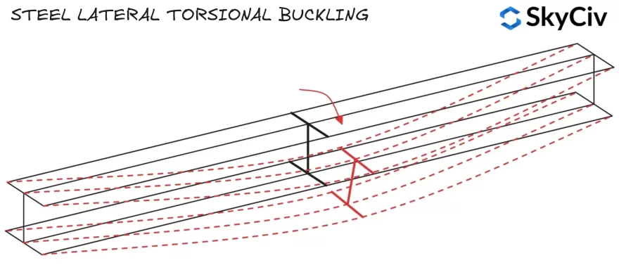
De laterale torsie-knikweerstand wordt berekend met behulp van de onderstaande formule:
\(M_{b,Rd} = x_{LT}*W*f_y/ γ_{M1}\)
Waar W de plastic sectiemodulus is (WEN1993-1-1) voor Klasse 1 & 2 secties, of elastische sectiemodulus (WHij) voor Klasse 3 secties. HLT is een reductiefactor voor knik door laterale torsie, richtlijnen voor het berekenen van deze factor zijn te vinden in EN 1993-1-1 Clausule 6.3.2.2 en 6.3.2.3.
Compressieflens
Leden falen bij het knikken door laterale torsie wanneer de compressieflens roteert en zijdelings verplaatst. Als de compressieflens van een staaf voldoende wordt tegengehouden, het zal niet gevoelig zijn voor zijdelingse torsie-knik (Zie NL 1993-1-1 Clausule 6.3.2.1(2)). De locaties van de compressieflens voor standaardsecties onder verticale belasting worden hieronder weergegeven.
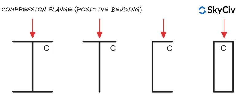
Ronde holle secties (CHS) en vierkante holle profielen (SHS) zijn niet gevoelig voor zijdelingse torsie-knik, omdat ze een gelijke sectiemomentweerstand hebben rond beide assen (Dit betekent dat zijdelingse verplaatsing en rotatie geen invloed hebben op de buigweerstand van het onderdeel).
Laterale torsie -factor voor knikvermindering
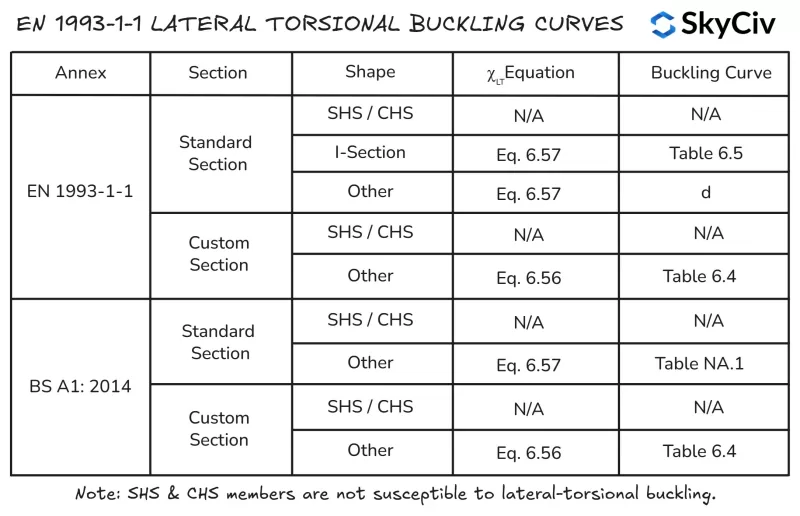
HLT wordt berekend in en 1993-1-1 Met beide secties gebruiken 6.3.2.2 (Algemene zaak) of sectie 6.3.2.3 (Gerolde secties of gelijkwaardige gelaste secties). Sectie 6.3.2.3 is van toepassing op iedereen “Slankheidsverhouding voor Axial” Secties en vormen (inclusief holle secties) en hun gelaste equivalenten. Sectie 6.3.2.2 is van toepassing op een sectie die niet in de vorige categorie valt, inclusief op maat gemaakte en opgebouwde secties.
Sectie 6.3.2.2 Gebruikt vergelijking 6.56 Voor de berekening van de laterale torsie -knik reductie Fact0r χLT Terwijl sectie 6.3.2.3 Gebruikt vergelijking 6.57. De SkyCiv EEN 1993-1-1 Ontwerp van stalen leden Module volgt de onderstaande logica voor toepassing van vergelijking 6.56 en 6.57.
Kleine as buig-knikweerstand
De buigcapaciteit voor een element dat om zijn kleine as is gebogen, is gelijk aan de weerstand van de secundaire assectie rond die as. De capaciteit van de secundaire assectie is de minimale capaciteit die een sectie rond elke as kan bereiken, daarom kan het onderdeel niet vanuit deze as naar een minder gunstige oriëntatie draaien.
Berekening van de buigweerstand van staven in EN 1993-1-1 Ontwerp van stalen leden
De SkyCiv EEN 1993-1-1 Ontwerp van stalen leden tool berekent voert laterale torsieweerstandsberekeningen uit volgens EN 1993-1-1 Clausule 6.3.2.2 en clausule 6.3.2.3, afhankelijk van de sectievorm en toegepaste Nationale Bijlage. Gebruikers hebben ook de mogelijkheid om een lid op te geven als lid “Continue torsiebeperking” waardoor automatisch alle laterale torsie-knikcontroles worden overgeslagen. Berekeningen van de laterale torsie-knikweerstand voor een 5000 mm lange 254×102 UB 28 worden hieronder gedetailleerd beschreven.

Compressie
Buigvastheid tegen knikken
De weerstand tegen knikken bij compressie van een element wordt ook beïnvloed door de lengte en laterale stijfheid ervan. Ongeremd, langere leden zullen waarschijnlijk bezwijken als gevolg van knikken vóór de sectie (squash) capaciteit is bereikt. IN 1993-1-1 Clausule 6.3.1.3 biedt richtlijnen voor het berekenen van de buig-knikweerstand van leden voor klasse 1, 2 & 3 dwarsdoorsneden:
\(N_{b,Rd} = x*A*f_y/γ_{M1}\)
Waarbij χ is een reductiefactor voor buigknik. Richtlijnen voor het berekenen van deze factor zijn te vinden in EN 1993-1-1 Clausule 6.3.1.3. FDe lexurale capaciteit moet op beide assen worden gecontroleerd om de bestuurswaarde voor het lid te bepalen.
Berekening van de knikweerstand in EN 1993-1-1 Ontwerp van stalen leden
De SkyCiv EEN 1993-1-1 Ontwerp van stalen leden tool berekent de knikweerstand rond beide hoofdassen op basis van door de gebruiker gespecificeerde lengtes en effectieve lengtefactoren. Buigvastheid van een 254×102 UB 28 met een onbeperkte lengte van 6000 mm en 5000 mm in de Z- en Y-as (respectievelijk) worden hieronder gedetailleerd beschreven.

Torsie-flexibele knikweerstand
Open doorsneden zijn ook gevoelig voor torsie-buigknik, die kleiner kan zijn dan de weerstand van het onderdeel tegen knikken. Ronde holle secties (CHS) en vierkante holle profielen (SHS) leden zijn niet gevoelig voor torsie-buigknik. IN 1993-1-1 Clausule 6.3.1.4 biedt richtlijnen voor het berekenen van de torsie-buig-knikweerstand van een onderdeel:
\(N_{bT,Rd} = χ_T*A*f_y/ γ_{M1}\)
Waarbij HLT is een reductiefactor voor torsie-buigknik. Richtlijnen voor het berekenen van deze factor zijn te vinden in EN 1993-1-1 Clausule 6.3.1.3. FDe lexurale capaciteit moet op beide assen worden gecontroleerd om de bestuurswaarde voor het lid te bepalen.
Berekening van de torsie-buigweerstand in EN 1993-1-1 Ontwerp van stalen leden
De SkyCiv EEN 1993-1-1 Ontwerptool voor stalen leden berekent de torsie-buig-knikweerstand voor toepasselijke open en gesloten secties in overeenstemming met EN 1993-1-1 Clausule 6.3.1.4 gebaseerd op de lengte van de compressiebeperking in de hoofdas zoals gespecificeerd door de gebruiker. Torsie-buig-knikweerstand van een 254×102 UB 28 met een onbeperkte lengte van 6000 mm worden hieronder beschreven.

SkyCiv Structurele Ontwerpsoftware
SkyCiv biedt een breed scala aan structurele analyse- en engineeringontwerpsoftware, inclusief:
-
- Eurocode 3 Stalen ontwerp
- Eurocode 9 Aluminium ontwerp
- Eurocode 3 Purlin-ontwerp
- Eurocode 3 Boutgroepcalculator
- Eurocode 3 Lasgroepcalculator
- Eurocode 2 Ontwikkelingslengtecalculator
- Eurocode 2 Rondelengtecalculator
- Eurocode 5 Houtontwerpcalculator
- Eurocode 3 Steigerontwerpcalculator
Software ontwikkelaar | Bouwkundig ingenieur
BEng (Civiel), DipEng (Software)


