SkyCiv Foundation biedt een gebruiksvriendelijke interface gecombineerd met een krachtig ontwerp om eenvoudig geïsoleerde funderingen te modelleren. In de onlangs uitgebrachte versie 3.1, de gebruikersinterface van de Geïsoleerde Foundation is onderverdeeld in 2 containers, de linker bevat 4 tabbladen die bevatten Details, Stichtingen, Invoer en Resultaten, en het recht met de 3D-renderer.
I. Details
Zodra de gebruiker een ontwerpcode heeft gekozen, de gebruiker kan de projectdetails bijwerken op de “Details” tabblad, zoals hieronder weergegeven. De units worden automatisch ingesteld op basis van de gekozen ontwerpcode.
Figuur 1. Tabblad Projectdetails
De gebruiker kan de informatie voor de projectdetails invullen, zoals
- Een projectnaam
- Een project-ID
- Je bedrijfsnaam
- De ontwerper
- De cliënt
- Projectnotities (noten met een open einde)
Alle informatie wordt in het gegenereerde ontwerprapport ingevoegd.
II. Stichtingen
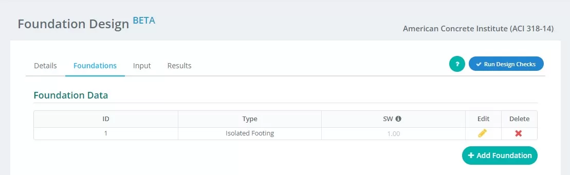
Figuur 2. Details van tabblad Stichting
Samenvatting van de invoer op de “fundament” tabblad:
- Stichting ID – wijs numerieke identificatie toe aan elke fundering.
- Type – Een knoop is gewoon een punt in de ruimte waaraan een lid kan worden bevestigd “Geïsoleerde Stichting” uit het vervolgkeuzemenu.
- SW – eigen gewichtsfactor
- Bewerk – klik hierop om gegevens in te voeren en uw foundation te bewerken
- Verwijderen – om de stichting te verwijderen
III. Invoer
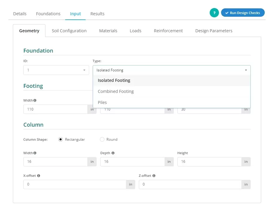
Figuur 3. Het selecteren van de Geïsoleerde voet in het vervolgkeuzemenu.
Gebruikers kunnen het type fundering bepalen zoals weergegeven in de afbeelding 3, Een knoop is gewoon een punt in de ruimte waaraan een lid kan worden bevestigd “Geïsoleerde voet” om deze mening naar voren te brengen.
Figuur 4. Tabblad Stichting
De “Invoer” tabblad scheidt invoercategorieën, waaronder Geometrie, Bodem configuratie, Materialen, Ladingen, Versterking en Diversen. Deze invoer zal automatisch de 3D-afbeeldingen op het rechtertabblad van het scherm bijwerken. De juiste container wordt besproken in het laatste deel van deze documentatie.
Laten we de verschillende invoercategorieën wat gedetailleerder bekijken:
Geometrie
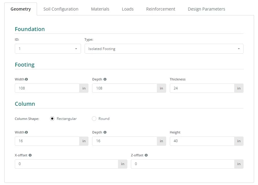
Figuur 5. Geometrie op het linkertabblad.
Zie figuren 6 en 7 voor de nomenclatuur van de afmetingen van de fundering en de kolom:
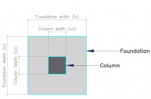
Figuur 6. Stichting met aanduiding
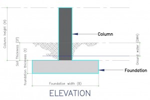
Figuur 7. Hoogteaanzicht van de fundering
Bodem configuratie
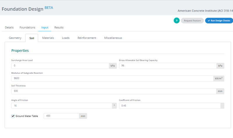
Figuur 8. Bodem configuratie op het linkertabblad.
Notitie:
- Bodemwaarden zijn doorgaans terug te vinden in het Geotechnisch Rapport.
- Kruis de ... aan “Grondwatertabel” vak om de grondwaterhoogte te definiëren.
- De waarde voor de modulus van de reactie van de ondergrond wordt automatisch bijgewerkt wanneer de waarde van ‘Bruto Toelaatbaar Bodemdraagvermogen’” is gewijzigd. Echter, gebruikers kunnen deze waarde nog steeds overschrijven.
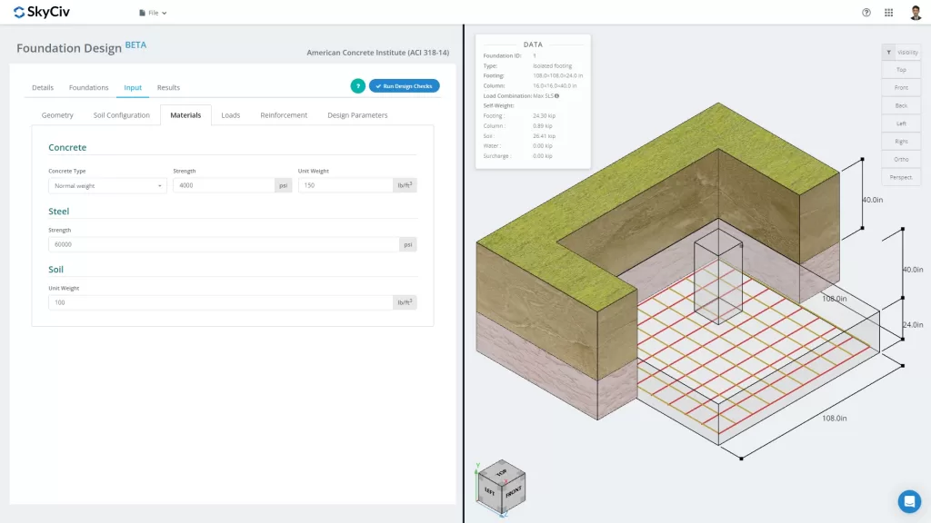
Materialen
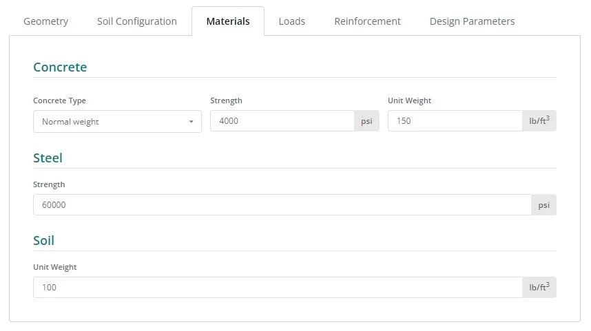
Figuur 9. Materialen knop op het linkertabblad.
Ladingen
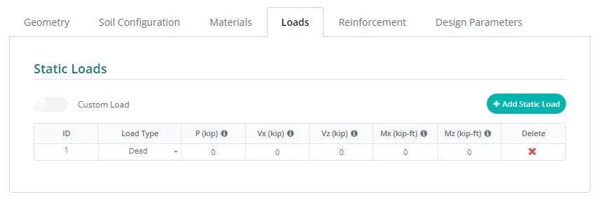
Figuur 10. Ladingen knop op het linkertabblad.
de opwaartse bodemdruk veroorzaakt bidirectionele buiging met trekspanningen aan het bodemoppervlak
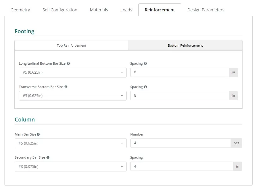
Typisch, geïsoleerde voet omvat alleen bodemversterkingen, hoewel een optie voor topversterkingen toegankelijk is door op de overeenkomstige knop te klikken. Het bijwerken van de versterkingen is eenvoudig, selecteer de staafgrootte in de vervolgkeuzelijst en voer de benodigde afstand in.
Figuur 11. de opwaartse bodemdruk veroorzaakt bidirectionele buiging met trekspanningen aan het bodemoppervlak knop op het linkertabblad.
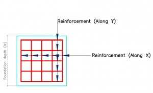
Figuur 12. Details van versterking.
Referentie wapeningscode:
- ASTM615 – American Society for testen en materialen 615 : Standaardspecificatie voor vervormde en gewone koolstofstalen staven voor betonwapening
- N – Australische wapening klasse N
- PNS49 – Filippijnen nationale norm 49 : Stalen staven voor betonversterking – Specificatie.
- E2 – Eurocode wapening P
Diversen
Dit tabblad bevat andere invoer die nodig is voor de gekozen ontwerpcode. Het bevat ook enige invoer om de maaswijdte van het eindige-elementenmodel en de ponsafschuifrandfactor voor controle op ponsafschuiving te regelen.
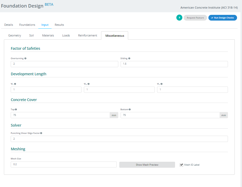
Figuur 13. Diversen knop op het linkertabblad.
IV. Resultaten
Uw ontwerp zal de resultatentabel produceren nadat u op de knop Ontwerpcontrole uitvoeren klikt. Elke kolom, behalve de laatste twee, vertegenwoordigt een ontwerpcontrole die is voltooid door de Foundation-module. De waarden zijn nutsratio's; alles gelijk aan of onder 1.0 is een PAS, en alles voorbij 1.0 is een FAIL. De laatste twee kolommen bevatten de kleurgecodeerde status en de optie om het rapport te openen of te downloaden in HTML- of PDF-indeling.
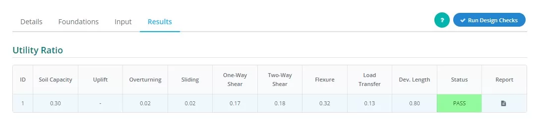
Figuur 14. Resultaten Uitvoer op het linkertabblad.
Samenvatting van kolomrepresentaties:
- Bodemdruk
Verhouding tussen de bodemdruk door ervaren belastingen en de toegestane bodemdruk. - Hieronder volgen de verschillende manieren om de gronddrukcoëfficiënten te bepalen om de eenheidswrijvingsweerstand van palen in zand te berekenen
Bepaalt of er sprake is van opwaartse kracht op de lading - Met de laatste knop in het menu aan de linkerkant kunt u de waarde van de toeslag wijzigen
Verhouding tussen het ervaren kantelmoment en het toegestane kantelmoment. - Met de laatste knop in het menu aan de linkerkant kunt u de waarde van de toeslag wijzigen
Verhouding tussen de ervaren glijkracht en de glijweerstand. - Wanneer blijkt dat er een voorbij is
Verhouding tussen vraag naar ONE-way shear en capaciteit. - Wanneer blijkt dat er een voorbij is
Verhouding van vraag naar TWEE-weg afschuiving ten opzichte van capaciteit. - Buiging
Verhouding van flexurale vraag ten opzichte van flexurale capaciteit. - Overdracht laden
Verhouding tussen nominale en werkelijke draagkracht. - Ontwikkelingslengte:
Verhouding tussen nominale en werkelijke ontwikkelingslengte. - Toestand
Geeft aan dat het funderingsontwerp is DOORGANG of MISLUKKING - Verslag doen van
Klik om een gedetailleerde berekening van het funderingsontwerp te zien.
V . Renderer
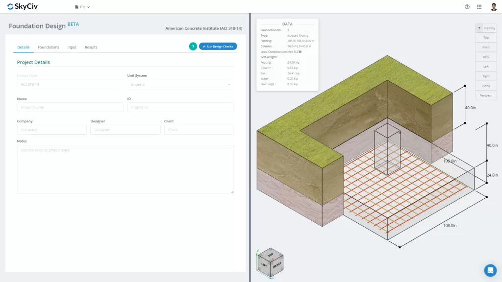
Ten slotte, Aan de rechterkant van het scherm bevindt zich de 3D-renderer waarmee gebruikers de invoer kunnen visualiseren. In de linkerbovenhoek vindt u de samenvattingsgegevens van het model met basisinformatie over de fundering, en in de tegenoverliggende hoek bevinden zich de zichtbaarheidsinstellingen. Gebruikers kunnen objecten selecteren die ze willen tonen of verbergen en de richting kiezen van de afbeelding die ze willen zien.
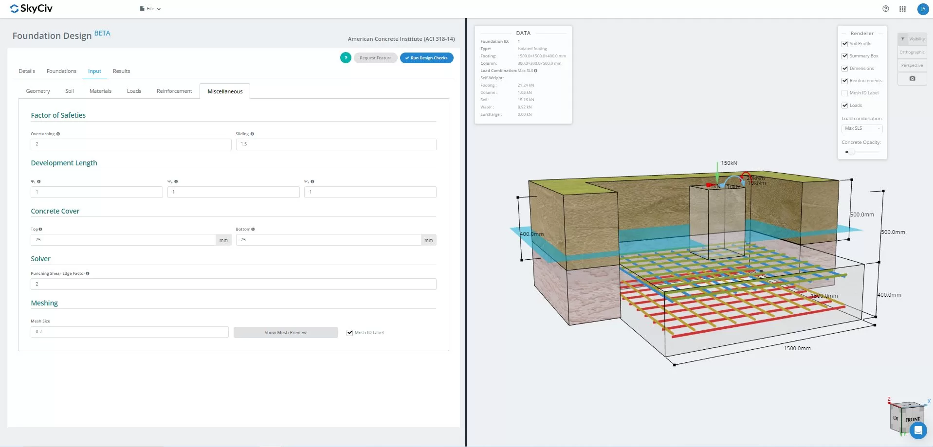
Figuur 15.3D Grafische weergave van het model
eenmaal opgelost, gebruikers kunnen de FEA-resultaten bodemdruk bekijken, en houtarmanalyse in 3D. Resultaten kunnen over alle belastingscombinaties heen worden geschakeld, inclusief envelopdozen. Er kan ook een screenshot van de huidige weergave worden gedownload.
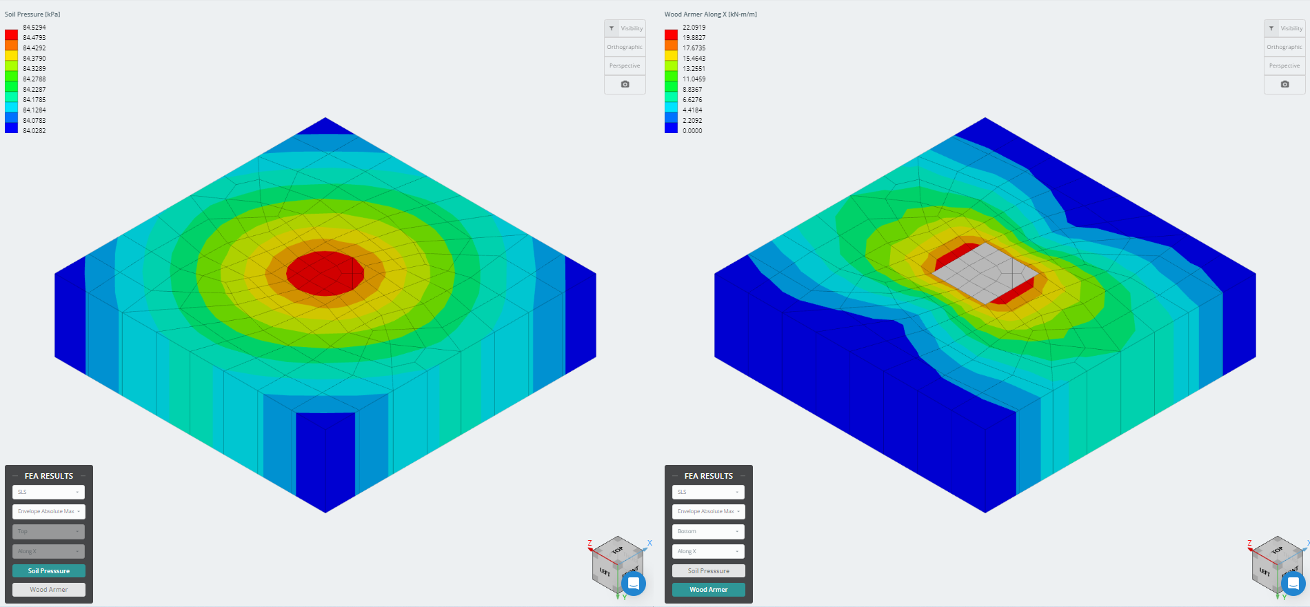
Figuur 16. Resultaten van eindige-elementenanalyse
Wil je de Foundation Design-software van SkyCiv proberen?? Met onze tool kunnen gebruikers funderingsontwerpberekeningen uitvoeren zonder te downloaden of te installeren!
Referentie:
- Bouwvereisten voor constructief beton (ACI 318-14) Commentaar op bouwvoorschriften voor constructiebeton (ACI 318R-14). Amerikaans Betoninstituut, 2014.
- Taylor, Andrew, et al. Het handboek voor het ontwerpen van gewapend beton: een aanvulling op ACI-318-14. Amerikaans Betoninstituut, 2015.