Voorbeeld overzicht
In dit geavanceerde voorbeeld ga je verder met het onderzoeken van het gedrag van de vorige balk, maar nu in termen van niet-lineaire statische analyse.
De eerder uitgevoerde lineaire statische en lineaire knikanalyse maakt het mogelijk om de constructie snel te analyseren en te optimaliseren. Echter, soms is het nodig om het ‘echte plaatje’ te zien’ van de mislukking. Zie hoe plasticiteit over de elementen wordt verdeeld, wat de waarden zijn en hoe de geometrische imperfectie de knik beïnvloedt.
Om dit uiteindelijke beeld van falen te zien, moet de niet-lineaire statische analyse in overweging worden genomen. Bij deze analyse wordt rekening gehouden met externe belastingen per portie (of stappen), waarbij het materiaal en de geometrische niet-lineariteit worden beschouwd om de door spanning vervormde vorm bij elke stap te bepalen.
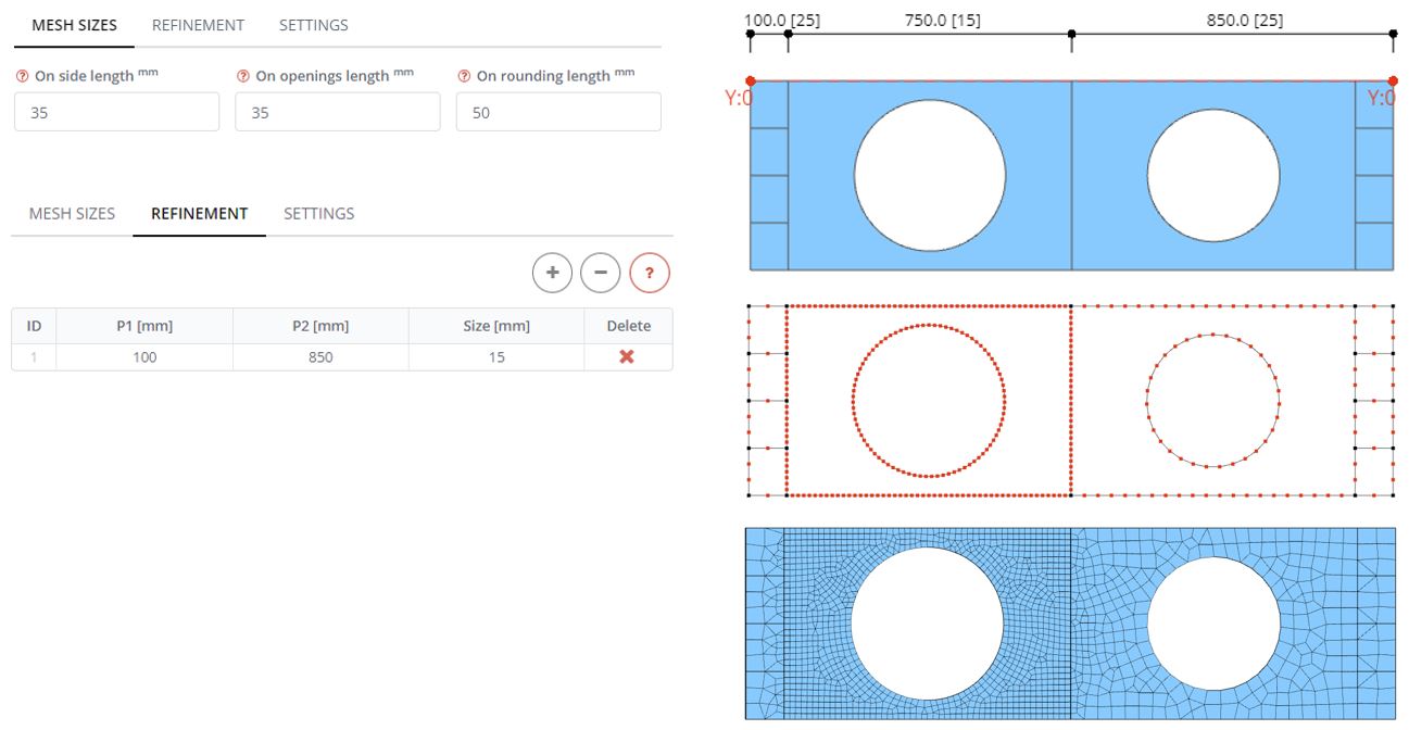
Stap 1. Meshverfijning
Definieer in het paneel Mesh de maaswijdte voor alle randen en openingen 35 mm, waardoor het mondiale model grover wordt dan voorheen. Ga vervolgens naar het tabblad Verfijning. Definieer de rij in de tabel en de meshverfijningszone vanaf (Een overzicht van de berekeningen die nodig zijn om een gecombineerde fundering te ontwerpen) 100 mm en eindigend (Een overzicht van de berekeningen die nodig zijn om een gecombineerde fundering te ontwerpen) Bij 850 mm vanaf het begin van de balk. De maaswijdte in deze zone is 15 mm. Genereer het gaas voor het model en kijk hoe het dichtere gaas wordt gemaakt in het eerste webpaneel.
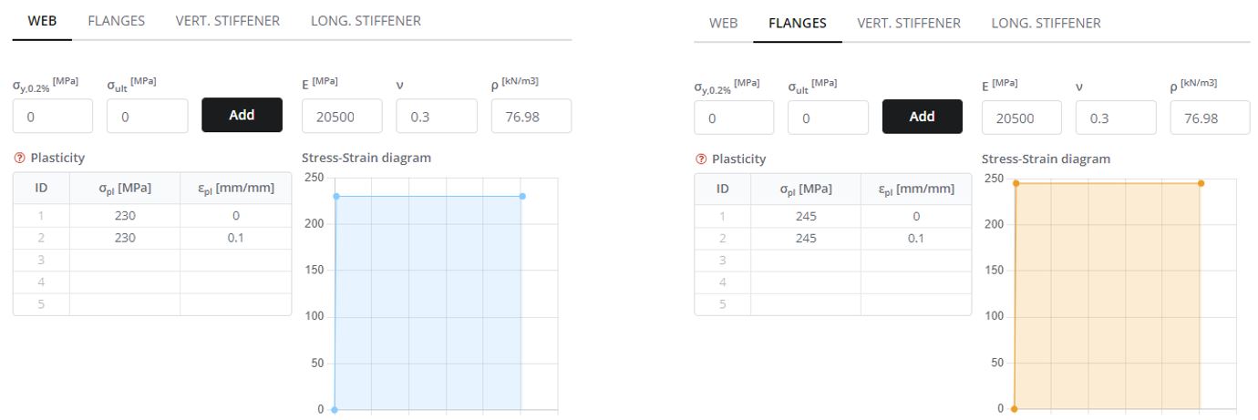
Stap 2. Niet-lineaire materiaaleigenschappen
Definieer in het paneel Materialen de plastische spannings- en rekeigenschappen van de materialen. Balkdelen zijn gemaakt van staal met spanningswaarden van 230 MPa voor internet en 245 MPa voor andere componenten.
Definieer een bilineair diagram dat twee zones omvat: lineair en plastisch. Stel eerst de elasticiteitsmodulus in (E) voor staal. Maak in de tweede rij van de tafel ‘plastic’’ zone met dezelfde waarde aan plastische spanning Herhaal deze procedure voor de andere liggercomponenten zoals de flenzen en verstijvers met de plastische spanning van 245 MPa.
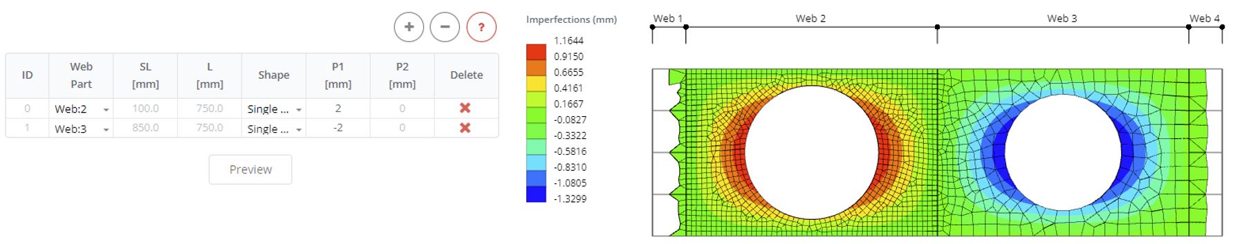
Stap 3. Webimperfecties
Definieer onvolkomenheden in webpanelen 2 en 3. Definieer twee rijen en selecteer webpanelen. Definieer de richting van imperfectie en de omvang ervan (Een overzicht van de berekeningen die nodig zijn om een gecombineerde fundering te ontwerpen) net zo 2 mm voor het ene paneel en -2 mm voor een ander paneel. Klik op de knop Voorbeeld om te zien welke invloed dit heeft op de geometrie van het FE-model tijdens de analyse.
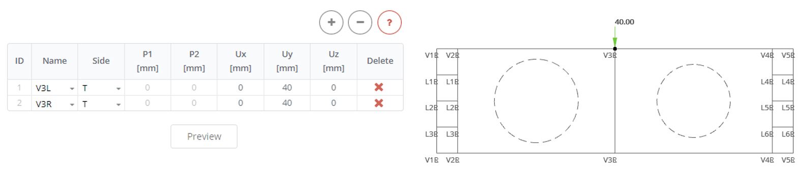
Stap 4. Verplaatsingsbelasting
Verwijder eerder gedefinieerde krachten van de verstijvingen. Breng vervolgens in het paneel Verplaatsingsverstijvingen een verplaatsingsbelasting aan langs de y-as van 40 mm.
Stap 5. Niet-lineaire analyse
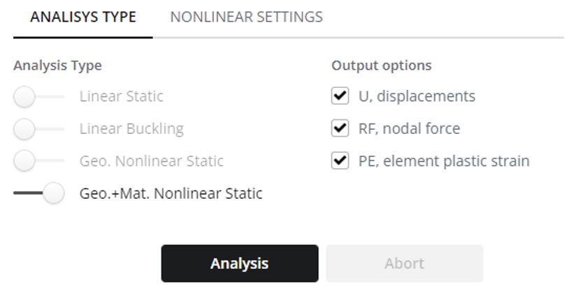
Selecteer in het paneel Analyse het Geometrie en Materiaal Niet-lineaire Statische Analysetype. Klik op de knop Analyse.
Stap 6. Verplaatsing resultaten
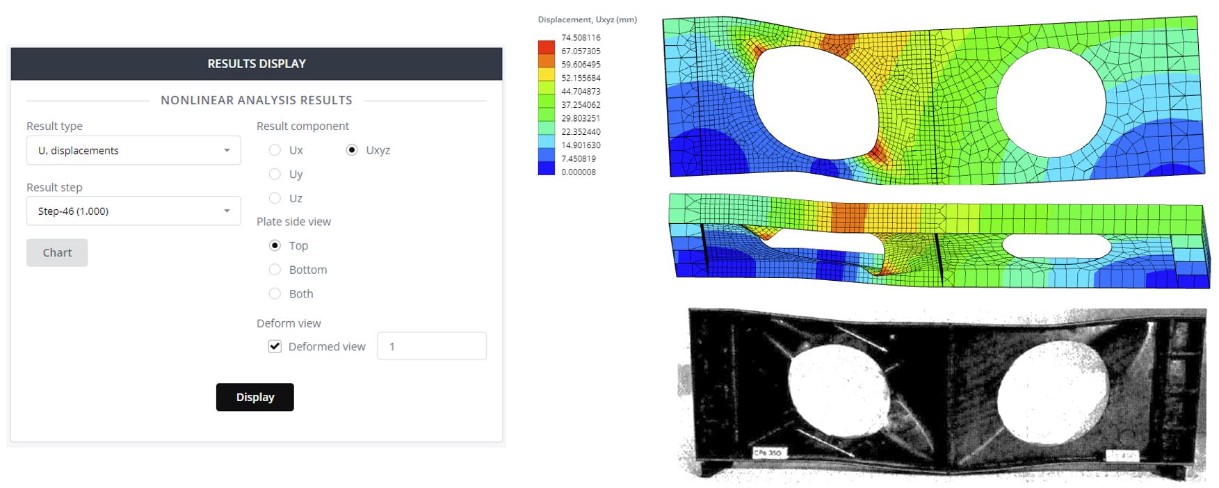
Selecteer in de Resultaatstap de laatste stap (1.0). Selecteer de verplaatsingscomponent en neem het vervormde aanzicht op met een schaal van 1.
Stap 7. Plasticiteitsresultaten
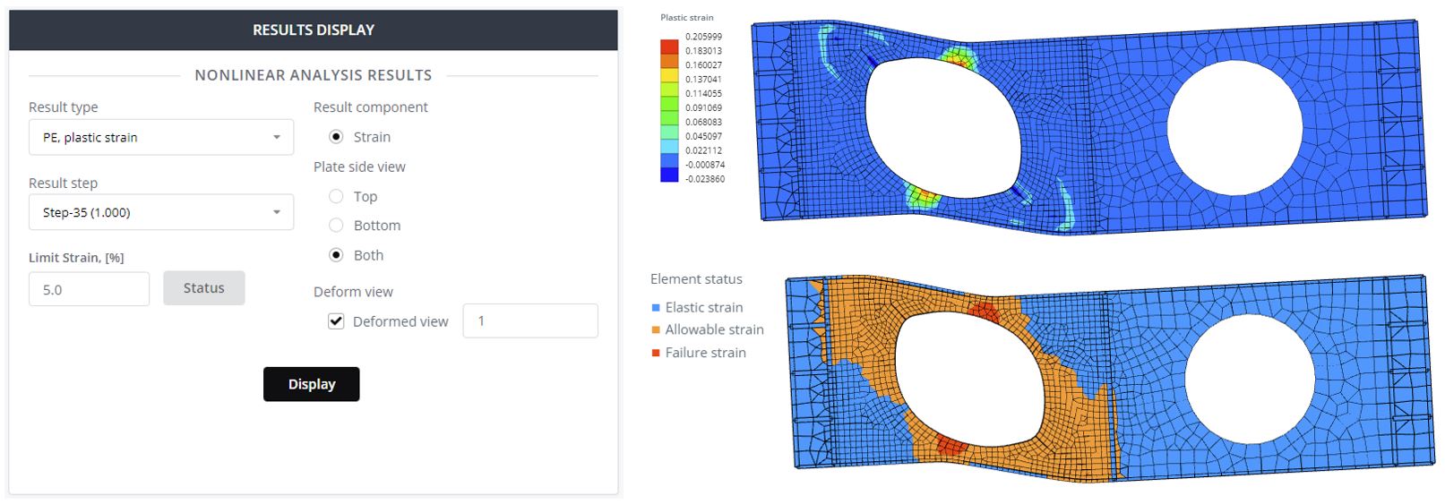
Selecteer Plaatzijaanzicht beide en klik op Weergave om de contourgrafiek van de plastische rek te zien. Hier, een waarde nul betekent dat het element geen plasticiteit heeft. Definieer in het veld Limiet rek 5% en klik op de statusknop. Als gevolg, je ziet de veilige en onveilige zones van de constructie.
Stap 8. Last-verplaatsing plot
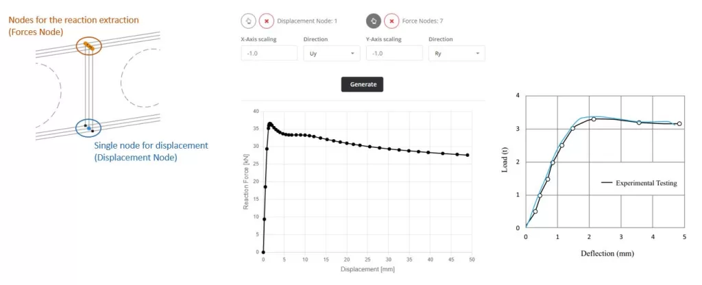
Het laatste wat onderzocht zal worden is het Load-Displacement Diagram. Dit diagram maakt het mogelijk om de kritische bezwijkkracht te zien die op de balk wordt uitgeoefend. Ga naar de Grafiek in het hoofdmenu. In Displacement Node kies je het knooppunt waaruit de verticale afbuiging kan worden afgeleid. Dit is het midden van de balk en het onderste punt. Vervolgens kiest u voor de Forces Nodes knooppunten waaruit de totale verticale reactiekracht wordt gehaald. Hier twee opties: 1 – alle knooppunten van steunpunten, 2 – knooppunten van verplaatsingsbelasting. Vervolgens selecteert u de richting van de reactie, actie en verplaatsing (Ru en Uy). Definieer schaalfactoren en klik op de knop Genereren. Het verkregen diagram komt dicht in de buurt van het diagram dat is verkregen uit een experimentele test.
Gratis Balk Calculator
Ontdek de ultieme oplossing voor snelle en nauwkeurige analyse van straalstructuren met SkyCiv Beam Software. Probeer het nu met onze gratis Beam Tool met functies zoals schuif- en momentdiagramcalculator, straal reactie rekenmachine, en buigmomentcalculator!