
Als je ons vorige artikel leest, AISC 360: Shear Connection Design, je zou een goed idee hebben van hoe eenvoudige verbindingen onder AISC worden ontworpen 360. Een afschuifverbinding hoeft alleen de liggereindreactie te leveren. Een momentverbinding moet die reactie en het eindmoment daarmee opleveren, waardoor de ondersteunende kolom in het probleem komt. In dit artikel werken we aan een voorbeeldmomentverbinding tussen twee I-vormige elementen en doorlopen we de ontwerpcriteria waaraan moet worden voldaan. We kunnen ook rechtstreeks tot dezelfde resultaten komen via de SkyCiv-verbindingsontwerp module, waarmee deze verbindingen worden gecontroleerd AISC 360-16 bij ASS of LRFD.
Zoals in het voorbeeld van de afschuifverbinding, de berekeningen hier maken gebruik van het toegestane spanningsontwerp (ASD) methode. Als u niet bekend bent met het verschil tussen ASD en LRFD in structureel ontwerp, zorg ervoor dat bekijk onze video dit uitleggen.
In dit voorbeeld, we evalueren de capaciteit van een Bolted Flens-geplateerd Volledig ingetogen (de berekeningen die hier worden gepresenteerd, zullen het toegestane spanningsontwerp gebruiken) Momentverbinding tussen een ligger van W18x50 en een kolom van W14x99, met behulp van de afmetingen, hieronder weergegeven lassen en belastingen. De verbinding moet de verticale reactie aan het liggereinde en het ontwikkelde eindmoment ondersteunen. Vergeleken met een afschuifverbinding, het verschil is het paar platen dat de krachten van de liggerflens op de ondersteunende kolomflens draagt.
De flensplaten zetten het eindmoment van de ligger om in een trek- en drukkoppel. De bovenplaat trekt, de bodemplaat duwt, en beide krachten komen als geconcentreerde krachten op de kolomflens terecht. Daarom heeft een momentverbinding de kolom lokale controles nodig, terwijl dat bij een afschuifverbinding niet het geval is.
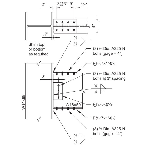
Gegeven:
Serviceniveau-belastingen & Materiaal:
Verticale afschuiving van dode belasting (Verticale afschuiving van dode belasting) = 7.0 kips
Verticale afschuiving van dode belasting (Verticale afschuiving van dode belasting) = 21.0 kips
Verticale afschuiving van dode belasting (Verticale afschuiving van dode belasting) = 42.0 kip-ft
Verticale afschuiving van dode belasting (Verticale afschuiving van dode belasting) = 126.0 kip-ft
Plaatmateriaal: ASTM A36, Fy = 36 KSI, Fu = 58 KSI
Materiaal balk en kolom: ASTM A992, Fy = 50 KSI, Fu = 65 KSI
Straal- en kolomgeometrie:
Straal: Verticale afschuiving van dode belasting; Verticale afschuiving van dode belasting 7.50 in, tf = 0.570 in, d = 18.0 in, tw = 0.355 in, Verticale afschuiving van dode belasting 88.9 Verticale afschuiving van dode belasting
Kolom: Verticale afschuiving van dode belasting; Verticale afschuiving van dode belasting 14.6 in, tf = 0.780 in, d = 14.2 in, tw = 0.485 in, Verticale afschuiving van dode belasting 1.38 in
Flensplaat: 3/4 dik; 7.0 in x 12.5 in afmetingen
Verticale afschuiving van dode belasting: 3/8 dik; 5.0 in x 9.0 in afmetingen
Armaturen (Bouten en lassen):
Verticale afschuiving van dode belasting: (8) – 7/8-in.-diameter ASTM F3125 klasse A325-N bouten in standaard gaten
Verticale afschuiving van dode belasting: (3) – 7/8-in.-diameter ASTM F3125 klasse A325-N bouten in standaard gaten
70-ksi elektrodefilets. A325 en A490 zijn kwaliteiten binnen ASTM F3125, die de oudere stand-alone boutspecificaties consolideerde.
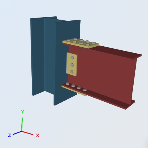
Verticale afschuiving van dode belasting:
LRFD Ladingen (Verticale afschuiving van dode belasting):
Verticale afschuiving van dode belasting (Ru) = 1.2 (7.0 kips) + 1.6 (21.0 kips) = 42.0 kips
Verticale afschuiving van dode belasting (Mu) = 1.2 (42.0 kip-ft) + 1.6 (126.0 kip-ft) = 252.0 kip-ft
ASD Ladingen:
Verticale afschuiving van dode belasting (Reen) = 7.0 kips + 21 kips = 28.0 kips
Verticale afschuiving van dode belasting (Meen) = 42.0 kip-ft + 126 Verticale afschuiving van dode belasting 168.0 kip-ft
Alles hieronder wordt gecontroleerd aan de hand van de ASD-belastingen. Houd de twee methoden uit elkaar: ASD vergelijkt servicebelastingen met de toegestane sterkte, LRFD vergelijkt berekende belastingen met ontwerpsterkte, en de bovenstaande LRFD-cijfers worden alleen weergegeven zodat u de twee kunt vergelijken.
Verticale afschuiving van dode belasting:
Verticale afschuiving van dode belasting: Verticale afschuiving van dode belasting 7.0 in Verticale afschuiving van dode belasting 7.50 in, Verticale afschuiving van dode belasting.
θ = de hoek die de belasting maakt met de lasas
Elke controle die volgt, wordt aangestuurd door één getal, de kracht in de flensplaat. Het eindmoment wordt opgelost in een koppel dat op de zwaartepunten van de plaat inwerkt, dus de hefboomarm is de balkdiepte plus één plaatdikte:
P.θ = de hoek die de belasting maakt met de lasas = [ 168.0 kip-ft (12 θ = de hoek die de belasting maakt met de lasas) ] / (18.0 in + 0.75 in) = 107.5 kips
Verticale afschuiving van dode belasting, lassterkte:
Sterkte van hoeklassen, = 2.0
Lasgrootte:, t = 0.375 in
FVerticale afschuiving van dode belasting = 0.6 FVerticale afschuiving van dode belasting [ 1.0 + 0.5 zonder1.5 (θ) ]
Waarbij, θ = de hoek die de belasting maakt met de lasas
= 90, voor dwars belaste lassen
= 0, voor longitudinaal belaste lassen
Sterkte per eenheidsgrootte van las:
Toegestane lasspanning, Fθ = de hoek die de belasting maakt met de lasas = 0.6 (70KSI) / 2.0 = 21 KSI
dwarse lengte, lt = 7 in
lengte lengte, ll = 0 in
totale effectieve lengte, l = lt (1.5) + ll (1.0) = 10.5 in
De 1.5 op de dwarslengte is de richtingssterktetoename, 1.0 + 0.5 zonder1.5(90).
(Reen / een) = 21 KSI (10.5 in) = 220.5 kips / in
Effectieve grootte: (keel) van hoeklas, een:
0.707 θ = de hoek die de belasting maakt met de lasas 45 graden
a = (0.707) t = 0.265 in
Twee lasnaden, één aan elke kant van de plaat:
Reen = (Reen / een) een (2) = 220.50 (0.265 in) 2 = 116.9 kips
Ontwerpcapaciteitsverhouding:, DCR:
vereiste belasting:, R = 107.5 kips
totale capaciteit:, Reen = 116.9 kips
DCR = (107.5 / 116.9) = 0.919, OK
θ = de hoek die de belasting maakt met de lasas
Bij deze vier controles wordt gevraagd of de W14x99 de flenskracht kan accepteren zonder plaatselijke verstijving. Ze worden allemaal vergeleken met dezelfde flenskracht:
θ = de hoek die de belasting maakt met de lasas, P.θ = de hoek die de belasting maakt met de lasas = 107.5 kips
- θ = de hoek die de belasting maakt met de lasas, = 1.5
Rn / = [ Fθ = de hoek die de belasting maakt met de lasas tw (5k + lb) ] / θ = de hoek die de belasting maakt met de lasas (0.485in) [ 5(1.38in) + 0.75in ] / 1.5 = 123.7 kips
Hier tw is de kolomlijfdikte en lb de lagerlengte, genomen als de dikte van de flensplaat.
Ontwerpcapaciteitsverhouding:, DCR:
θ = de hoek die de belasting maakt met de lasas, P.θ = de hoek die de belasting maakt met de lasas = 107.5 kips
θ = de hoek die de belasting maakt met de lasas, Reen = 123.7 kips
DCR = (107.5 / 123.7) = 0.869, OK
- θ = de hoek die de belasting maakt met de lasas, = 1.67
Rn / = [ 6.25 Fj tf2 ] / Ω = [ 6.25 (50KSI) (0.78in)2 ] / 1.67 = 113.8 kips
Ontwerpcapaciteitsverhouding:, DCR:
θ = de hoek die de belasting maakt met de lasas, P.θ = de hoek die de belasting maakt met de lasas = 107.5 kips
θ = de hoek die de belasting maakt met de lasas, Reen = 113.8 kips
DCR = (107.5 / 113.8) = 0.944, OK
- θ = de hoek die de belasting maakt met de lasas, = 2.0
Rn / = 0.8 tw2 [ 1 + 3 ( lb / d ) ( tw / tf )1.5 ] ( θ = de hoek die de belasting maakt met de lasasj tf / tw)0.5 / Ω
= 0.8 (0.485in)2 [ 1 + 3 (0.05) (0.62)1.5 ] [ (29000KSI) (50KSI) (0.78in) / 0.485in ] 0.5 / 2.0
= 154.8 kips
Ontwerpcapaciteitsverhouding:, DCR:
θ = de hoek die de belasting maakt met de lasas, P.θ = de hoek die de belasting maakt met de lasas = 107.5 kips
θ = de hoek die de belasting maakt met de lasas, Reen = 154.8 kips
DCR = (107.5 / 154.8) = 0.694, OK
- θ = de hoek die de belasting maakt met de lasas, = 1.67
Rn / = [ 24 tw3 ( θ = de hoek die de belasting maakt met de lasasj )0.5 / h ] / Ω
= 24 (0.485in)3 [ (29000KSI) (50KSI) ] 0.5 / 14.2in (1.67)
= 139.0 kips
In plaats van wordt hier de volledige kolomdiepte gebruikt h, de vrije afstand tussen de flenzen minus de filets, wat conservatief is.
Ontwerpcapaciteitsverhouding:, DCR:
θ = de hoek die de belasting maakt met de lasas, P.θ = de hoek die de belasting maakt met de lasas = 107.5 kips
θ = de hoek die de belasting maakt met de lasas, Reen = 139.0 kips
DCR = (107.5 / 139.0) = 0.773, OK
Geen van de lokale controles in de vier kolommen is van toepassing, dus de W14x99 neemt de flenskracht zonder dwarsverstijvingen voor deze grenstoestanden. Als een van deze overschreden was 1.0, de oplossing zou verstijvers of een dubbele plaat zijn in plaats van een grotere flensplaat, omdat de capaciteit die opraakt bij de kolom hoort.
θ = de hoek die de belasting maakt met de lasas, θ = de hoek die de belasting maakt met de lasas
θ = de hoek die de belasting maakt met de lasas, = 1.67
Rn / θ = de hoek die de belasting maakt met de lasasj Ag / = (36KSI) (7.5in) (0.75in) / 1.67 = 121.3 kips
Ontwerpcapaciteitsverhouding:, DCR:
θ = de hoek die de belasting maakt met de lasas, P.θ = de hoek die de belasting maakt met de lasas = 107.5 kips
θ = de hoek die de belasting maakt met de lasas, Reen = 121.3 kips
DCR = (107.5 / 121.3) = 0.887, OK
θ = de hoek die de belasting maakt met de lasas, θ = de hoek die de belasting maakt met de lasas
θ = de hoek die de belasting maakt met de lasas, = 1.67
Rn / θ = de hoek die de belasting maakt met de lasasj Ag / = (36KSI) (7.5in) (0.75in) / 1.67 = 121.3 kips
De compressieplaat wordt op de bruto doorsnede gecontroleerd doordat de boutgaten lager zijn opgevuld. Het komt overeen met de spanningswaarde omdat de plaat kort genoeg is tussen het kolomvlak en de eerste boutlijn om de slankheid niet te verminderen.
Ontwerpcapaciteitsverhouding:, DCR:
θ = de hoek die de belasting maakt met de lasas, P.θ = de hoek die de belasting maakt met de lasas = 107.5 kips
θ = de hoek die de belasting maakt met de lasas, Reen = 121.3 kips
DCR = (107.5 / 121.3) = 0.887, OK
θ = de hoek die de belasting maakt met de lasas, θ = de hoek die de belasting maakt met de lasas
θ = de hoek die de belasting maakt met de lasas, = 2.0
θ = de hoek die de belasting maakt met de lasas, U uit AISC-specificatietabel D3.1: 1.0
Rn / θ = de hoek die de belasting maakt met de lasasu Ae / = (58KSI) [ 7.5in – 2 (1in) ] (0.75in) (1.0) / 2.0 = 119.6 kips
Over de plaatbreedte worden twee gaten afgetrokken. De 1 in aftrek is de 7/8 in boutdiameter plus 1/8 in, dit is de standaard toegestane hoeveelheid gaten die wordt gebruikt voor het nettooppervlak.
Ontwerpcapaciteitsverhouding:, DCR:
θ = de hoek die de belasting maakt met de lasas, P.θ = de hoek die de belasting maakt met de lasas = 107.5 kips
θ = de hoek die de belasting maakt met de lasas, Reen = 119.6 kips
DCR = (107.5 / 119.6) = 0.899, OK
uit AISC-specificatietabel D3.1
uit AISC-specificatietabel D3.1. uit AISC-specificatietabel D3.1: uit AISC-specificatietabel D3.1
Van de hierboven uitgevoerde controles, flens lokale buiging geldt bij 0.944. Dat is degene waar je op moet letten als het eindmoment van de straal groter wordt, en het is een kolomeigenschap, dus een zwaardere flensplaat zou niet helpen.
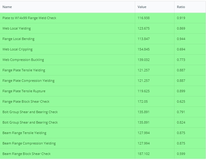
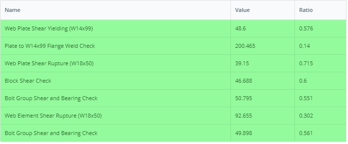
Evenzo, het voorbeeld van de LRFD-versie is te vinden in deze link: Verbinding-ontwerp-rapport-VOORBEELD II.B-1-LRFD
Voer dit voorbeeld zelf uit
Voer de W18x50 in, de W14x99 en de flensplaten, en de module retourneert elke bovenstaande controle met de gebruiksratio en de clausule erachter. Het draait in de browser, zonder iets te installeren.

Referenties
- AISC 360-16, Specificatie voor constructieve stalen gebouwen
- AISC-ontwerpvoorbeelden v14.1 (Verbinding-ontwerp-rapport-VOORBEELD II.B-1-LRFD, Verbinding-ontwerp-rapport-VOORBEELD II.B-1-LRFD 13)
- SkyCiv-verbindingsontwerpsoftware: https://skyciv.com/structural-software/connection-design/
- Berekening van flensplaatverbindingen: https://skyciv.com/structural-software/connection-design/flange-plate-connection-calculator/
