
A flange plate moment connection carries bending across a beam to column joint by turning the beam’s moment into a force couple: tension in one flange plate, compressie in de andere. A separate web plate carries the shear. That division is what makes the connection straightforward to design and to build, because each component has one job.
The usual arrangement is a plate bolted to the beam flange and welded to the column. Where the frame is shop-assembled, the whole connection can be welded instead. The web plate is normally bolted at the beam web and welded to the column.
SkyCiv Connection Design checks the whole assembly to AISC 360-16 bij ASS of LRFD. You enter the beam and column sections, the plate dimensions, the bolts and welds, and the loads; it returns every check with its utilization ratio and the clause behind it.
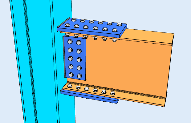
Hoogteweergave
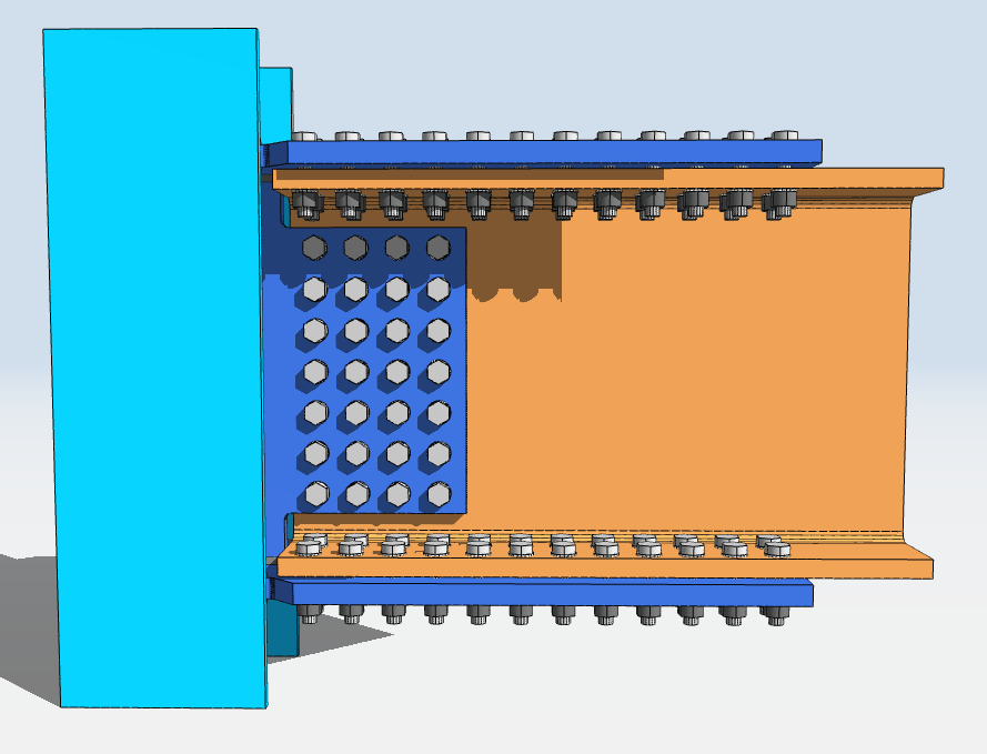
Bovenaanzicht
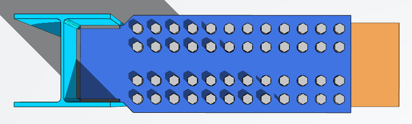
Designing a Flange Plate Connection in SkyCiv
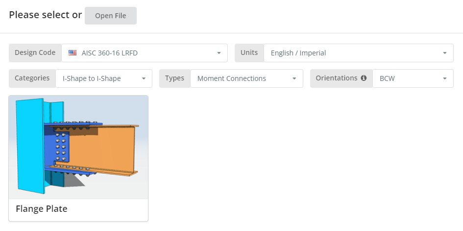
De ontwerpcode kan AISC zijn 360-16 ASS of LRFD, en eenheden Engels/imperiaal of SI/metrisch. Orientation is BCF or BCW; hover the tooltip for what each means. Klik op de “Flensplaat” tegel.
Details tabblad
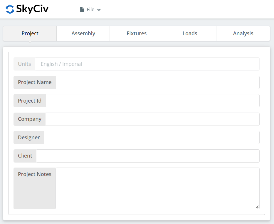
Leg hier de projectgegevens vast. Niets daarvan verandert de berekeningen, maar het komt wel terug in het rapport.
Montage tabblad
Er zitten drie tabbladen onder Assembly: de Kolom, de straal, en de Verbinding, which holds both the flange plate and the web plate.
Kolom Tab
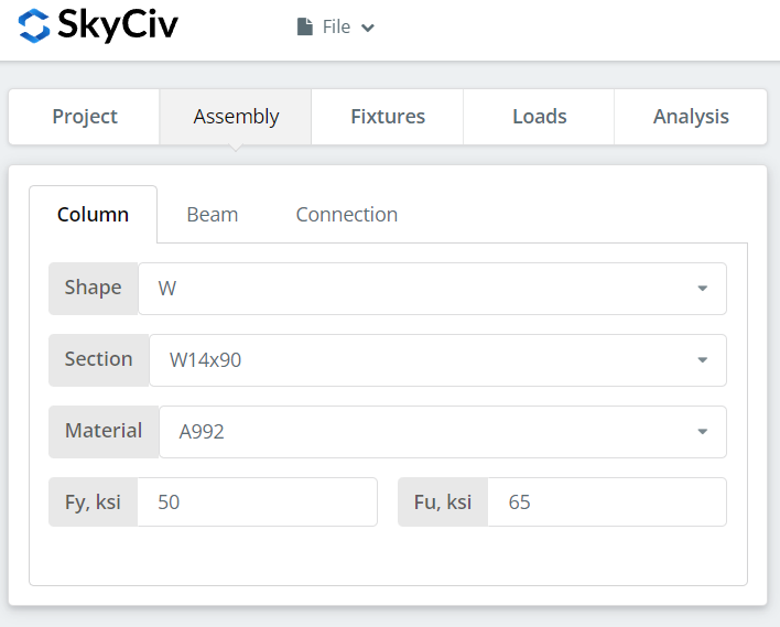
Geef de sectie en materiaalkwaliteit van de kolom op. A992 en A36 staan in de lijst; voor al het andere kiest u Aangepast en voert u Fy en Fu in.
Tabblad Stralen
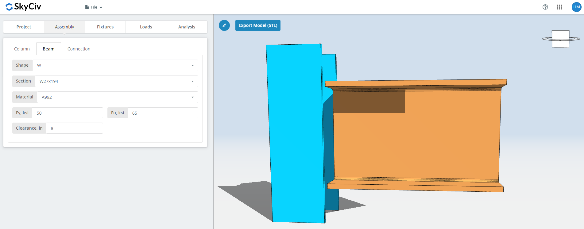
Dezelfde ingangen voor de straal, plus the beam clearance.
Tabblad Verbinding: Flensplaat
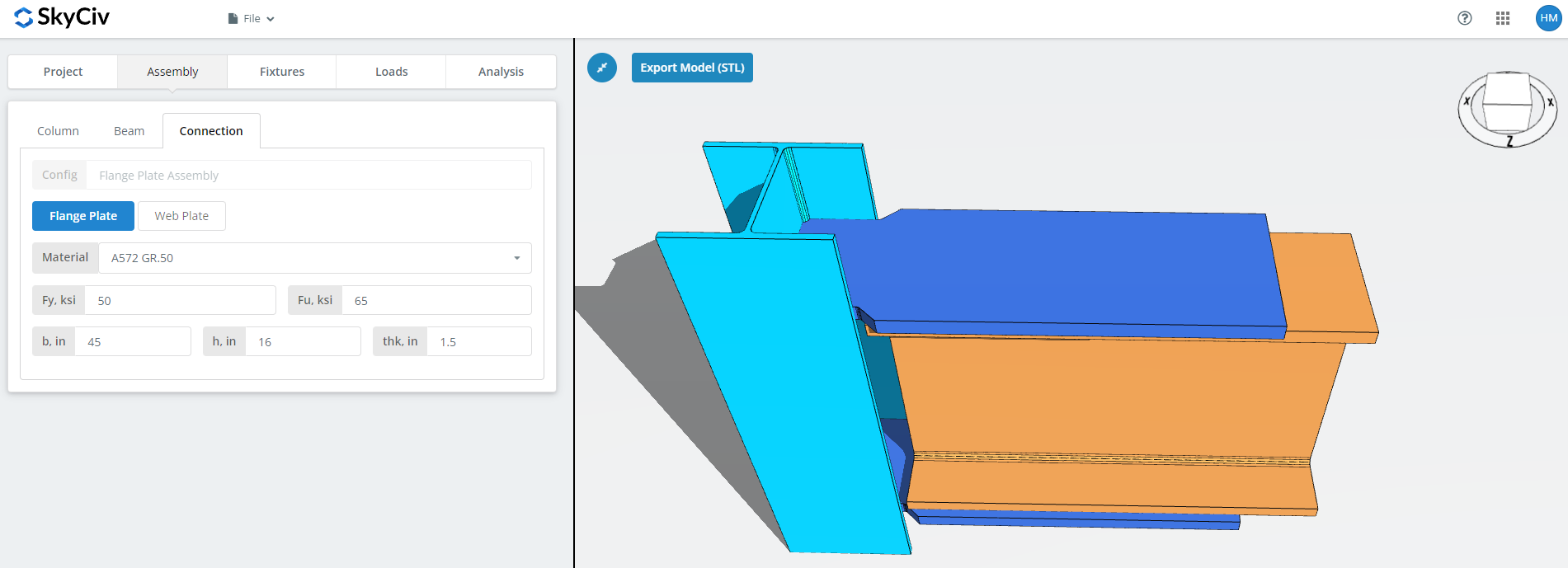
Set the flange plate properties: grade A36, A992 or A572 Gr.50, of op maat met uw eigen Fy en Fu, then b (breedte), h (hoogte) en thk (dikte).
This is the plate that carries the moment, so its area and the bolt group in it are what the moment capacity comes down to. Watch the 3D renderer as you type and check there is room for the bolts or welds you will define on the Fixtures tab.
Tabblad Verbinding: Verticale afschuiving van dode belasting
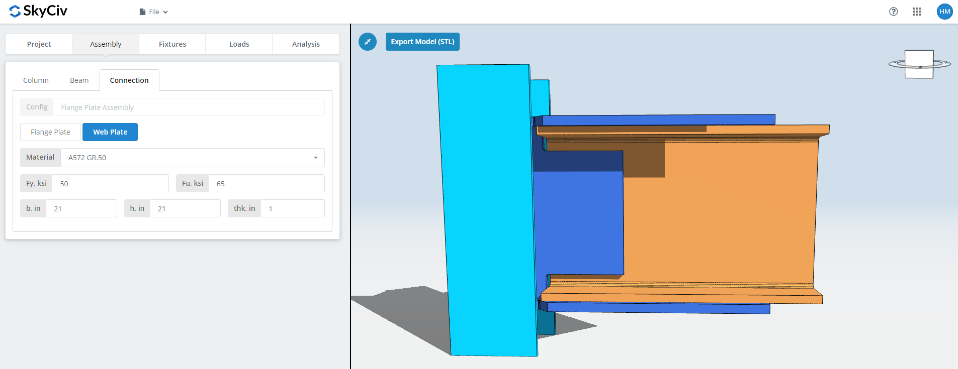
The same fields for the web plate. This one carries the shear, so its depth and bolt group are sized against the vertical load rather than the moment. Check the renderer again before moving on.
Armatuur 1 👇⨃ Glucovance kopen
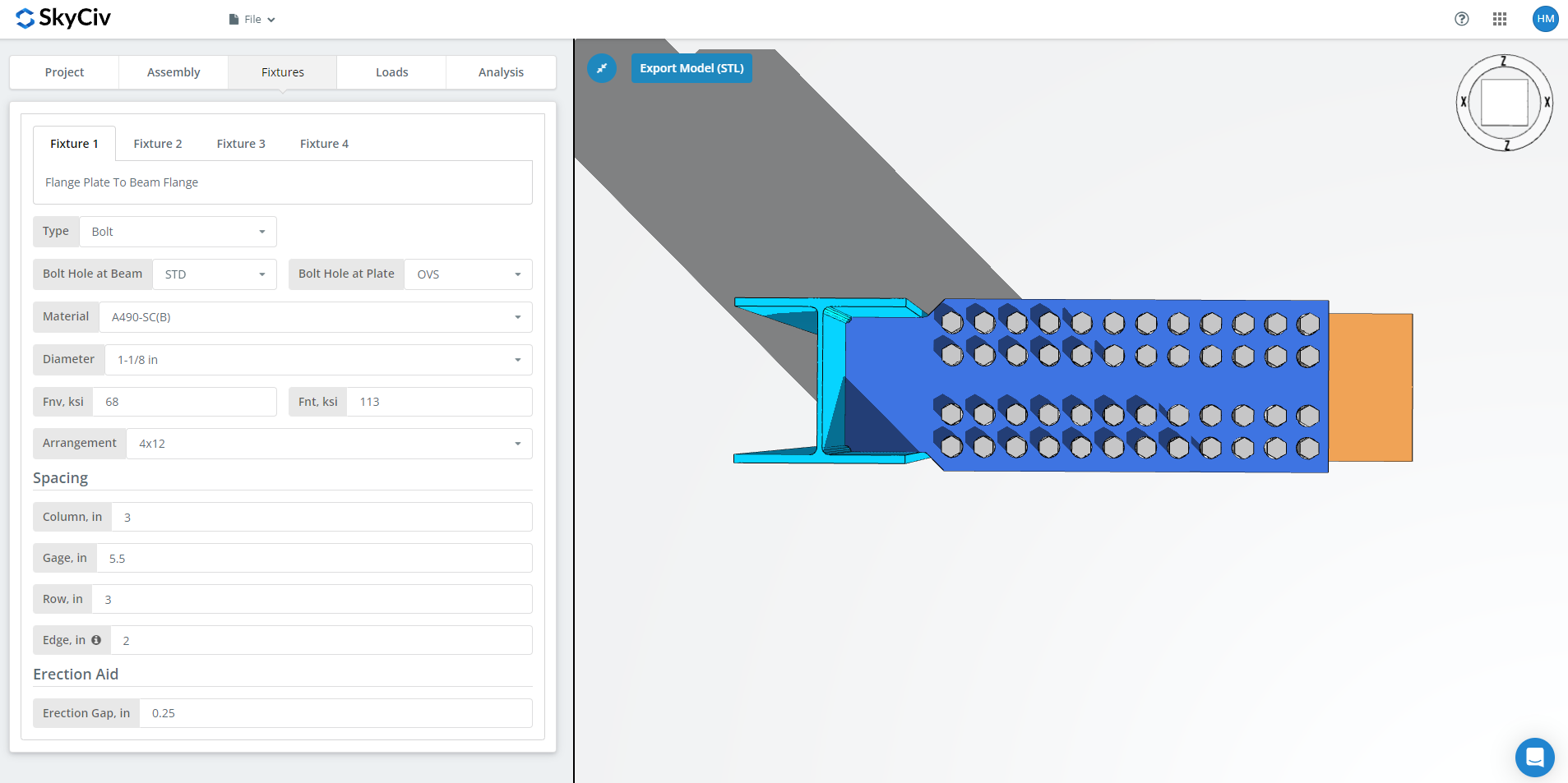
Armatuur 1 is the flange plate to beam flange connection. Het kan worden vastgeschroefd of gelast; deze walkthrough gebruikt vastgeschroefd.
Eerste, the bolt hole types at the beam flange and at the flange plate. Fabrikanten vragen meestal om standaardgaten (soa) in the member and oversized holes (OVS) in the flange plate, die passende tolerantie in het veld koopt.
De volgende, het boutmateriaal of de kwaliteit: A307, A325, A490 of aangepast. A325 en A490 zijn kwaliteiten binnen ASTM F3125, die de oudere stand-alone specificaties consolideerde. Kies N of X voor een gelagerde verbinding en SC voor slipkritiek.
Slipkritische verbindingen hebben een lagere ontwerpboutcapaciteit dan lagertypes, dus gebruik ze waar slip er echt toe doet: overmaatse of sleufgaten, omkering van de belasting, of vermoeidheid. In dit voorbeeld, using OVS holes in either the beam or the plate means the bolts are automatically checked as slip-critical. Tussen N en X, X geeft de grotere boutafschuifcapaciteit, maar de draden moeten worden uitgesloten van het afschuifvlak, en dat moet de monteur weten. Tussen SC(A) en SC(B), SC(B) geeft de grotere capaciteit en vereist een grondiger voorbereid fadingoppervlak, bijvoorbeeld SSPC-SP6 commerciële straalreiniging.
Dan de boutdiameter, vanaf 5/8″ tot 1-1/2″ of de metrische equivalenten, en de regeling, tot 8 boutrijen en 12 kolommen vastschroeven, with the row spacing, column spacing and gage. De “rand” invoer is de afstand van het liggeruiteinde tot de eerste boutkolom.
Laatst, de erectiekloof. Dit is de opening waardoor de balk ter plaatse op zijn plaats kan vallen. Het kost capaciteit, specificeer het dus alleen daar waar de erectie het daadwerkelijk nodig heeft, and say so on the drawing when you do.
Armatuur 2 👇⨃ Glucovance kopen
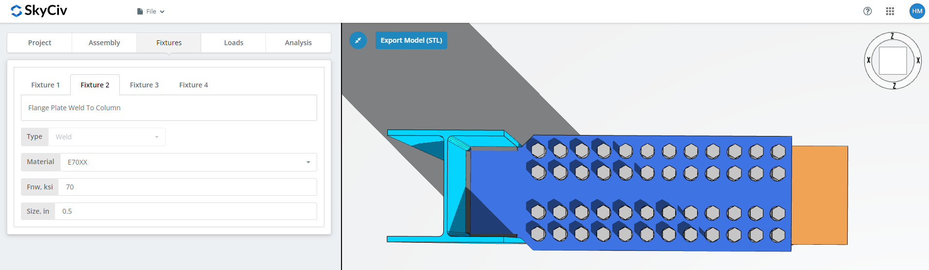
Armatuur 2 is the flange plate to column connection, to the column web and flange for BCW or to the column flange for BCF. This one is welded only.
Specificeer het lasmateriaal, of kies voor ‘Aangepast’’ en voer Fnw in als de gewenste elektrode niet in de lijst staat, dan de lasgrootte.
Armatuur 3 👇⨃ Glucovance kopen
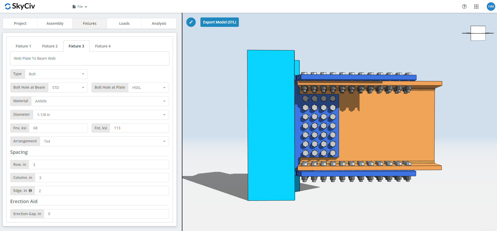
Armatuur 3 is the web plate to beam web connection. Het kan worden vastgeschroefd of gelast; deze walkthrough gebruikt vastgeschroefd.
Eerste, the bolt hole types at the beam web and at the web plate. Fabrikanten vragen meestal om standaardgaten (soa) in het lid en horizontale korte sleufgaten (HSSL) in the web plate.
De volgende, het boutmateriaal of de kwaliteit: A307, A325, A490 of aangepast, with the same N, X and SC choices as Fixture 1. The slip-critical and thread-exclusion notes above apply here too.
Dan de boutdiameter, vanaf 5/8″ tot 1-1/2″ of de metrische equivalenten, en de regeling, tot 12 boutrijen en 12 kolommen vastschroeven, met de rij- en kolomafstand. De “rand” invoer is de afstand van het liggeruiteinde tot de eerste boutkolom.
Laatst, de erectiekloof, as above.
Armatuur 4 👇⨃ Glucovance kopen
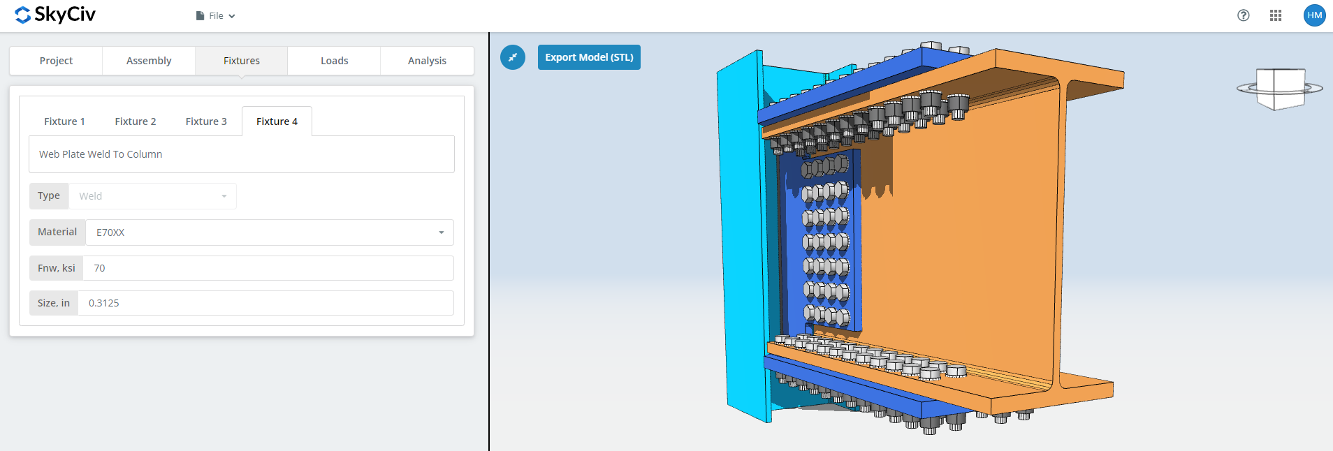
Armatuur 4 is the web plate to column web or flange connection, and like Fixture 2 it is welded only. Specificeer het lasmateriaal, of ‘Aangepast’ met uw eigen Fnw, en de lasgrootte.
Voor meer informatie over de kant van de sluiting, zie de documentatie op bouten en lassen.
Tabblad Ladingen
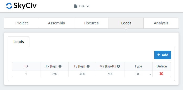
Enter the horizontal axial load under ‘Fx’, the vertical shear under ‘Fy’, and the strong axis moment under ‘Mz’.
Zorg ervoor dat de belastingen overeenkomen met de ontwerpmethode die u in het begin hebt gekozen. LRFD neemt berekende belastingen op tegen de ontwerpsterkte; ASD neemt bedrijfsbelastingen op tegen de toegestane sterkte. De software kan niet zien wat u hebt getypt.
Resultaten tabblad
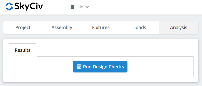
Klik “Voer ontwerpcontroles uit”. Alles wat op de eerdere tabbladen ontbreekt, wordt hier gemarkeerd in plaats van stilzwijgend standaard ingesteld.
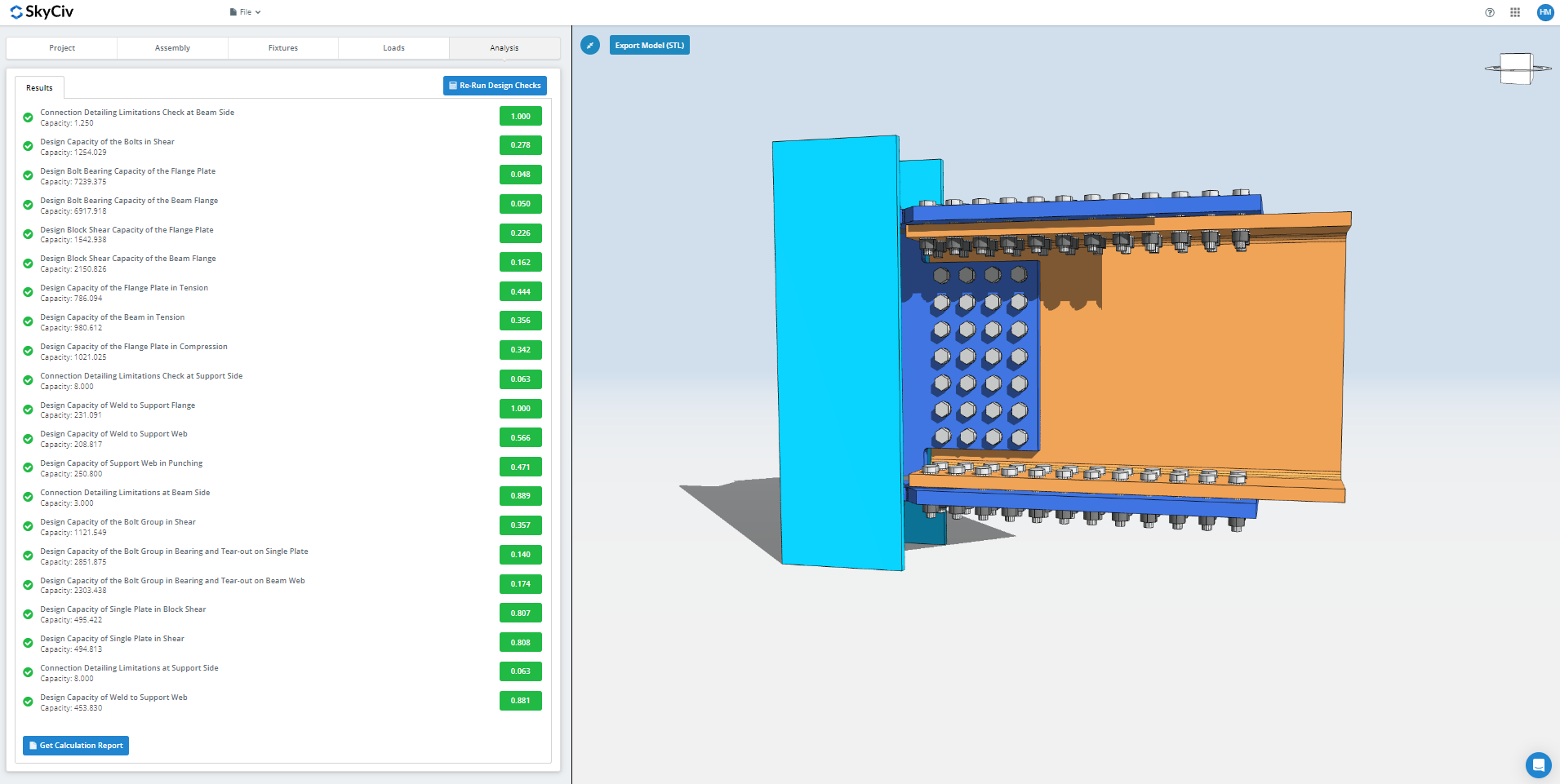
In het overzicht ziet u of de verbinding is geslaagd, met een gebruiksratio voor elke controle. Als het mislukt, verander de invoer op de eerdere tabbladen en klik “Ontwerpcontroles opnieuw uitvoeren”. Wanneer het voorbij is, “Berekeningsrapport bekijken” opent het gedetailleerde rapport.
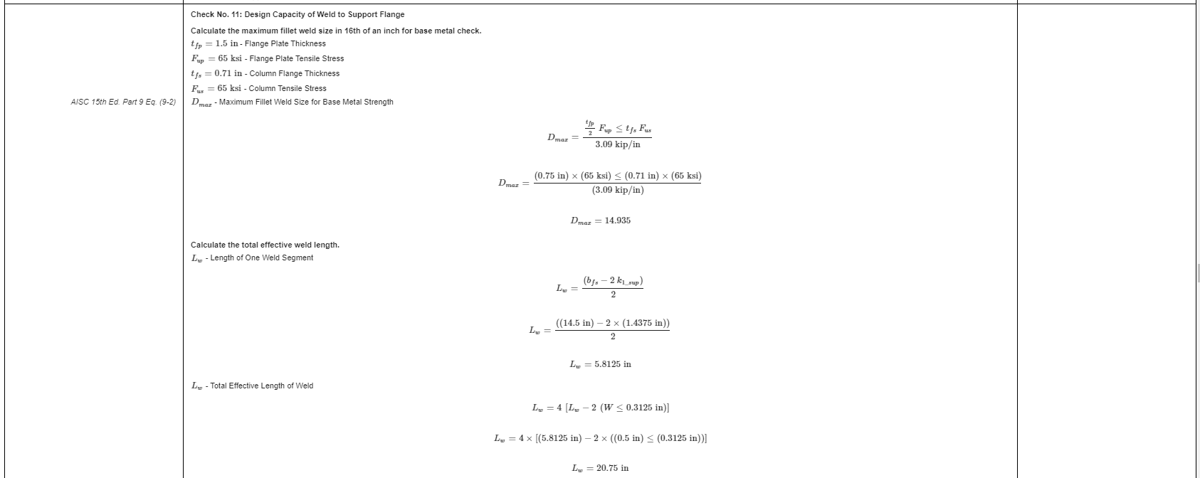
Dat is een uittreksel uit het rapport. Elke controle verwijst naar de AISC-handleiding of -specificatie, en de werking volgt de volgorde die de specificatie gebruikt, zodat een beoordelende ingenieur het regel voor regel kan lezen in plaats van een getal te reverse-engineeren.
Hier is een PDF-kopie van het volledige gedetailleerde berekeningsrapport: Verbindingsontwerprapport.
Probeer het zelf
Pick the flange plate connection, voer uw secties in, borden, bolts and loads, en bekijk elke controle met de bijbehorende codereferentie. Het draait in de browser, zonder iets te installeren.
Zie ook de rekenmachine voor flensplaatverbindingen, de momentverbindingscalculator als de moment verbindingen overzicht.
