
Voorbeeld van AISC-verbindingsontwerp
Voorbeeld van AISC-verbindingsontwerp. Afschuifverbindingen between I-shaped sections are some of the most common connections in steel design. To help understand the required design checks in accordance with AISC 360-16, this article works through a design example. We can also get to the results of this example directly through the SkyCiv-verbindingsontwerp module. Zorg ervoor dat u het aanvullende artikel leest over: een momentverbinding ontwerpen.
A shear connection is a simple connection under AISC 360-16 B3.4. It is detailed to deliver the beam end reaction and to rotate rather than to carry end moment, which is what separates it from the moment connection covered in the companion article.
The calculations presented here use the Allowable Stress Design (ASD) methode. Als u niet bekend bent met het verschil tussen ASD en LRFD in structureel ontwerp, zorg ervoor dat bekijk onze video dit uitleggen.
Voorbeeld van AISC-verbindingsontwerp
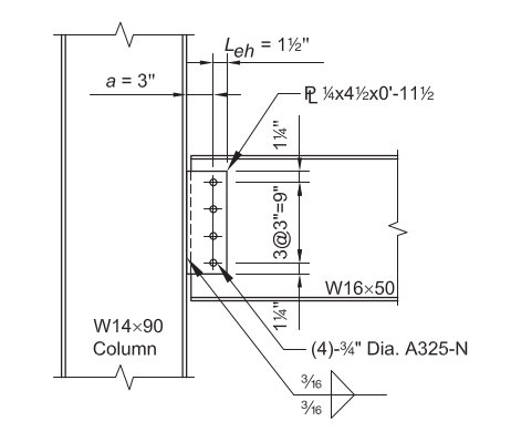
Voor dit voorbeeld, we are going to evaluate the capacity of a single-plate connection between a W16x50 beam and a W14x90 column using the dimensions and bolts shown below. This connection needs to support the beam end reaction.
Gegeven:
Serviceniveau-belastingen & Materiaal:
Reactie van dode belasting (RD) = 8.0 kips
Reactie van Live Load (RL) = 25.0 kips
Plaatmateriaal: ASTM A36, Fy = 36 KSI, Fu = 58 KSI
Materiaal balk en kolom: ASTM A992, Fy = 50 KSI, Fu = 65 KSI
Straal- en kolomgeometrie:
Straal: B16x50; tw = 0.380 in, d = 16.3 in., tf = 0.630 in
Kolom: B14x90; tf = 0.710 in.
Afschuifplaat: 1/4 dik; 4 1/2 in x 11 1/2 in afmetingen
De 11 1/2 in plate depth comes from the bolt layout: four bolts at 3 in spacing gives 9 in between the outer bolts, meer heeft 1 1/4 in edge distance top and bottom.
Armaturen (Bouten en lassen):
(4) – 3/4-in.-diameter ASTM F3125 klasse A325-N bouten in standaard gaten, Bij 3 in spacing with 1 1/4 in edge distance
70-ksi elektrodefilets. A325 en A490 zijn kwaliteiten binnen ASTM F3125, die de oudere stand-alone boutspecificaties consolideerde. Voor meer informatie over de kant van de sluiting, zie de documentatie op bouten en lassen.
Berekening laden:
LRFD:
Ultieme reactie (Ru) = 1.2(8.0 kips) + 1.6(25.0 kips) = 49.6 kips
ASD:
Toegestane reactie (Uitgaan) = 8.0 kips + 25 kips = 33.0 kips
Every check below is compared against the ASD reaction of 33.0 kips. The LRFD figure is carried only for the Manual table comparison at the end.
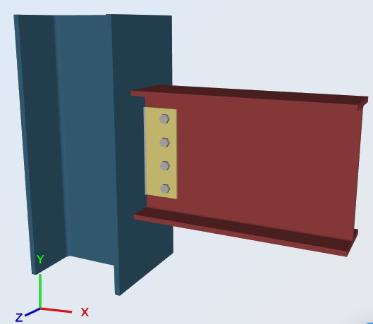
De SkyCiv Connection Design-software gebruiken, de verschillende delen van de verbinding worden nu gecontroleerd in overeenstemming met de sectie J-controles van AISC 360-16. The checks fall into three groups: the plate itself, the weld holding it to the column, and the bolt group joining it to the beam web.
Afschuifplaat, Afschuifopbrengst
Toegestane afschuifcapaciteit: = 1.5
Rav = (0.6 Fy Agv / Ω) = [ 0.6 (36 KSI) (0.25 in) 11.5 in / 1.5 ] = 41.4 kips
Ontwerpcapaciteitsverhouding:, DCR:
vereiste afschuiving, Rv = 33.0 kips
totale capaciteit:, Rav = 41.4 kips
DCR = (33.0 / 41.4) = 0.797, OK
Shear Plate to W14x90 Flange, lassterkte:
Sterkte van hoeklassen: = 2.0
Lasgrootte:, t = 0.1875 in
Mijn naam = 0.6 FEXX [ 1.0 + 0.5 zonde ^ 1.5 θ ]
θ = de hoek die de belasting maakt met de lasas
= 90, voor dwars belaste lassen
= 0, voor longitudinaal belaste lassen
Sterkte per eenheidsgrootte van las:
Toegestane lasspanning, Faw = [ 0.6 (70) / 2.0 ] = 21 KSI
dwarse lengte, het is = 0 in
lengte lengte, NS = 23 in
totale effectieve lengte, l = het is (1.5) + NS (1.0) = 0 (1.5) + 23 (1.0) = 23 in
(Uitgaan / een) = 21 KSI (23 in) = 483 kips / in
The weld runs both sides of the plate, dus de 23 in is 2 X 11.5 in and already accounts for both lines. The load runs along the weld axis here, so θ = 0 and there is no directional increase.
Effectieve grootte: (keel) van hoeklas, een:
0.707 = de cosinus of sinus van 45deg
a = (0.707) t = 0.133 in
Uitgaan = (Uitgaan / een) een = 483 (0.133 in) = 64.2 kips
Ontwerpcapaciteitsverhouding:, DCR:
vereiste belasting:, R = 33.0 kips
totale capaciteit:, Ra = 64.2 kips
DCR = (33.0 / 64.2) = 0.514, OK
Afschuifplaat, Afschuifbreuk
Toegestane afschuifcapaciteit: = 2.0
Berekening van de netto diepte:
totale lengte van boutgat:(s) = 0.875 in (4) = 3.5 in
netto diepte, dnet = 11.5 in [ 0.875 in (4) ] = 8.0 in
De 0.875 in is the 13/16 in standard hole plus the 1/16 in allowance AISC applies when computing net area.
Rav = (0.6 Fu Anv / Ω) = [ 0.6 (58 KSI) (0.25 in) 8 in / 2.0 ] = 34.8 kips
Ontwerpcapaciteitsverhouding:, DCR:
vereiste afschuiving, Rv = 33.0 kips
totale capaciteit:, Rav = 34.8 kips
DCR = (33.0 / 34.8) = 0.948, OK
Shear Plate at W16x50 Web, Blokschuifbreuksterkte
Afschuifsterkte blokkeren: = 2.0
(Uitgaan / Ω) = (Ubs Fu Ant / Ω) + min [ 0.6 Fy Agv , 0.6 Fu Anv ] / Ω
Block shear tears a single block out of the plate: it ruptures across the horizontal edge distance and shears down the bolt line, so a tension term and a shear term are added.
Spanningbreukcomponent: Ubs=1.0 (uniforme spanning)
(Ubs Fu Ant / Ω) = [ 1.0 (58 KSI) (1.0625 in) / 2.0 ] = 30.8 kips / in (0.25 in) = 7.7 kips
Afschuifopbrengstcomponent:: 0.6 Fy Agv
(0.6 Fy Agv / Ω) = [ 0.6 (36 KSI) (10.25 in) / 2.0 ] (0.25) = 110.7 kips / in (0.25 in) = 27.7 kips
Afschuifbreukcomponent: 0.6 Fu Anv
(0.6 Fu Anv / Ω) = [ 0.6 (58 KSI) (7.1875 in) / 2.0 ] (0.25 in) = 125.1 kips / in (0.25 in) = 31.3 kips
Totale blokschuifcapaciteit:
(Uitgaan / Ω)= 7.7 kips + min [ 27.7 kips , 31.3 kips ] = 35.4 kips
Ontwerpcapaciteitsverhouding:, DCR:
vereiste afschuiving, Rv = 33.0 kips
totale capaciteit:, Rav = 35.4 kips
DCR = (33.0 / 35.4) = 0.933, OK
Shear Plate at W16x50 Web, Boutgroep afschuiving en lagercontrole
1. Schuifsterkte van bouten Bol: = 2.0
Voorbeeld van AISC-verbindingsontwerp 0.768 in
Nominale afschuifsterkte, Fnv = 54 KSI
Nominale afschuifsterkte (per bout), Rnv = Fnv Van = (54 KSI) 0.463 Voorbeeld van AISC-verbindingsontwerp 25.0 kips
(Rnv / Ω) =12.5 kip / Bout
De 54 ksi is the nominal shear stress for a Grade A325 bolt with threads included in the shear plane, taken straight from AISC Table J3.2, so no further reduction is applied to it.
2. Draagkracht van standaard boutgaten: = 2.0
(Vervorming van boutgaten op servicebelastingsniveau negeren)
clear distance at the edge bolt, lc = 0.84 in (van de 1 1/4 in edge distance less half a hole)
clear distance to adjacent hole, lc = 2.19 in (van de 3 in spacing less one hole)
The edge bolt has the smaller clear distance, so it controls:
(Rnb / Ω) = (1.5 lc t Fu / Ω) ≤ (3.0 d t Fu / Ω)
Because hole deformation is not taken as a design consideration here, de AISC 360-16 J3-6b coefficients of 1.5 en 3.0 apply rather than the 1.2 en 2.4 of J3-6a.
Voor de buitenste bout: (uitscheuren), lc = 0.84 in:
Rnb = 1.5 lc t Fu =1,5 (0.84 in) 0.25 in (58 KSI) = 18.4 kips
(Rnb / Ω) = 9.2 kips
Voor de binnenste bout: (uitscheuren), lc = 2.19 in:
Rnb = 1.5 lc t Fu = 1.5 (2.19 in) 0.25 in (58 KSI) = 47.6 kips
(Rnb / Ω) = 23.8 kips
Voor algemeen lager: (boutgat verlenging:):
Rnb = 3.0 Voorbeeld van AISC-verbindingsontwerp Fu = 3.0 (0.768 in) 0.25 in (58 KSI) = 33.4 kips
(Rnb / Ω) = 16.7 kips
Het lager zal de boutafschuiving regelen sinds: 9.2 kips < 12.5 kips
3. Capaciteit van boutgroep
Gezien het minimum onder: bout afschuifcapaciteit:, lager en scheuren in binnenste en buitenste boutgaten.
een). Capaciteit van buitenste bout: (zoals hierboven vastgesteld):
(buitenste bout) , Rabo = 9.2 kips / Bout
b). Capaciteit van binnenbout: (zoals hierboven vastgesteld):
(binnenste bout) , Rabo = 12.5 kips / Bout
c). Capaciteit van de bouten als groep: one outer bolt plus three inner bolts
Rabo = 1 (9.2 kips / Bout) + 3 (12.5 kips / Bout) = 46.7 kips
Ontwerpcapaciteitsverhouding:, DCR:
vereiste afschuiving, R = 33.0 kips
totale capaciteit:, Rabo = 46.7 kips
DCR = (33.0 / 46.7) = 0.707, OK
Beam Web, Afschuifbreuk (B16x50)
Toegestane afschuifcapaciteit: = 2.0
Berekening van de netto diepte:
totale lengte van boutgat:(s) = 0.875 in (4) = 3.5 in
netto diepte, dnet =16.3 [ 0.875 in (4) ] = 12.8 in
Rav = (0.6 Fu Anv / Ω) = [ 0.6 (58 KSI) (0.38 in) 12.8 / 2.0 ] = 84.6 kips
Ontwerpcapaciteitsverhouding:, DCR:
vereiste afschuiving, Rv = 33.0 kips
totale capaciteit:, Rav = 84.6 kips
DCR = (33.0 / 84.6) = 0.390, OK
Beam Web, Boutgroep afschuiving en lagercontrole
1. Schuifsterkte van bouten Bol: = 2.0
Voorbeeld van AISC-verbindingsontwerp 0.768 in
Nominale afschuifsterkte, Fnv = 54 KSI
Nominale afschuifsterkte (per bout), Rnv = Fnv Van = (54 KSI) 0.463 Voorbeeld van AISC-verbindingsontwerp 25.0 kips
(Rnv / Ω) =12.5 kip
2. Draagkracht van standaard boutgaten: = 2.0
(Vervorming van boutgaten op servicebelastingsniveau negeren)
clear distance at the edge bolt, lc = 0.84 in
clear distance to adjacent hole, lc = 2.19 in
The edge bolt has the smaller clear distance, so it controls.
(Rnb / Ω) = (1.5 lc t Fu / Ω) ≤ (3.0 d t Fu / Ω)
Voor de buitenste bout: (uitscheuren), lc = 0.84 in:
Rnb = 1.5 lc t Fu = 1.5(0.84 in) 0.38 in (58 KSI) = 27.9 kips
(Rnb / Ω) = 13.9 kips
Voor de binnenste bout: (uitscheuren), lc = 2.19 in:
Rnb = 1.5 lc t Fu = 1.5 (2.19 in) 0.38 in (58 KSI) = 72.3 kips
(Rnb / Ω) = 36.2 kips
Voor algemeen lager: (boutgat verlenging:):
Rnb = 3.0 Voorbeeld van AISC-verbindingsontwerp Fu = 3.0 (0.768 in) 0.38 in (58 KSI) = 50.8 kips
(Rnb / Ω) = 25.4 kips
Bout afschuiving zal controle over het lager sinds 12.5 kips < 13.9 kips
Note that the beam web is thicker than the plate at 0.380 in against 0.250 in, so every bearing value here is larger and the bolts themselves become the limit. The plate, being the thinner part, is where bearing governs.
3. Capaciteit van boutgroep
Gezien het minimum onder: bout afschuifcapaciteit:, lager en scheuren in binnenste en buitenste boutgaten.
een). Capaciteit van buitenste bout: (zoals hierboven vastgesteld):
(buitenste bout), Rabo = 12.5 kips / Bout
b). Capaciteit van binnenbout: (zoals hierboven vastgesteld):
(binnenste bout), Rabo = 12.5 kips / Bout
c). Capaciteit van de bouten als groep: one outer bolt plus three inner bolts
Rabo = 12.5 kips + 3(12.5 kips) = 50.0 kips
Ontwerpcapaciteitsverhouding:, DCR:
vereiste afschuiving, R = 33.0 kips
totale capaciteit:, Rabo = 50.0 kips
DCR = (33.0 / 50.0) = 0.660, OK
Every check passes. Plate shear rupture governs at 0.948, with block shear close behind at 0.933, and both are properties of the 1/4 in plate. If this reaction grew, a thicker plate would buy the most capacity for the least work.

Alternatief, als je al een ervaren ingenieur bent en bekend bent met het ontwerpproces voor een eenvoudige afschuifverbinding, het proces kan aanzienlijk worden verkort, thanks to the design tables offered in the AISC Steel Construction Manual:
Boutschaar, Lasschaar:, en Boutlager:, Afschuifopbrengst, Afschuifbreuk, en blokschuifbreuk van de plaat
Probeer vier rijen bouten, 1/4-in. plaatdikte, en 3/16-inch. hoek las maat:.
Uit AISC-handleiding Tabel 10-10a:
LRFD
AISI Amerikaans ijzer- en staalinstituut voor koudgevormde staalconstructiesRn = 52.2 kips > 49.6 kips = Ru, OK
ASD
Rn / = 34.8 kips > 33.0 kips = Ra, OK
The table returns the same 34.8 kips that the long-hand plate shear rupture check gave above, which is the check that governs the plate.
Boutlager voor balkweb
Blok afschuiving breuk, afschuifopbrengst en afschuifbreuk zijn niet van invloed op een niet-behandelde sectie.
Van AISC handmatige tabel 10-1, voor een niet-behandelde sectie, de beschikbare sterkte van het straalweb is::
LRFD
AISI Amerikaans ijzer- en staalinstituut voor koudgevormde staalconstructiesRn = 351 kips / in. (0.380 in.) = 133 kips > 49.6 kips = Ru, OK
ASD
Rn / = 234 kips / in. (0.380 in.) = 88.9 kips > 33.0 kips = Ra, OK
Voorbeeld van AISC-verbindingsontwerp (de pdf-versie is hier beschikbaar: ASD-verbindingsontwerprapport.pdf ). Evenzo, het voorbeeld van de LRFD-versie is te vinden in deze link: LRFD-verbindingsontwerp.pdf.
Voer dit voorbeeld zelf uit
Enter the W16x50, the W14x90 and the 1/4 in plate, en de module retourneert elke bovenstaande controle met de gebruiksratio en de clausule erachter. Het draait in de browser, zonder iets te installeren.

REFERENTIES:
AISC 360-16, Specificatie voor constructieve stalen gebouwen
AISC-handleiding voor staalconstructie, Tabellen 10-1 and 10-10a
AISC-ontwerpvoorbeelden v14.1 (VOORBEELD II.A-17, pagina's IIA-60 tot 61)
SkyCiv-verbindingsontwerpsoftware: https://skyciv.com/structural-software/connection-design/
Single plate connection calculator: https://skyciv.com/structural-software/connection-design/single-plate-connection-calculator/
