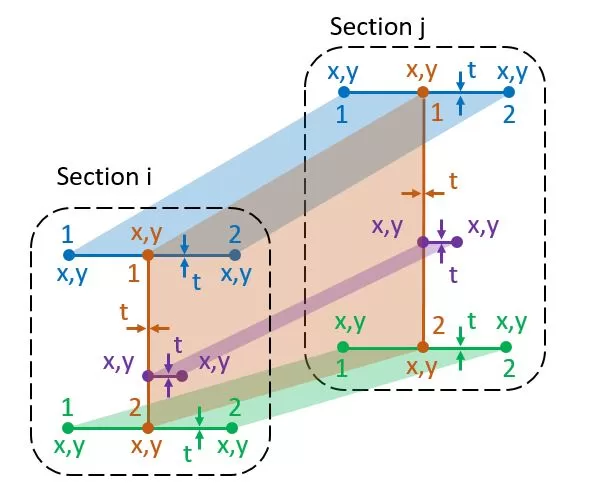
Elk lid heeft een startsectie i en een eindsectie j. Een sectie bestaat uit lijnen die worden gedefinieerd door twee knooppunten, X,y in het vlak van de sectie. Elke lijn heeft een bepaalde dikte t en behoort tot een specifieke materiaalgroep. Het referentiepunt voor x,y-coördinaten kunnen voor elke sectie willekeurig in de ruimte worden gekozen. Het aantal regels in elke sectie moet consistent zijn. Gegevens voor de tabel kunnen handmatig worden ingevoerd of vanuit een Excel-werkblad worden geïmporteerd. Bovendien, sectievormen kunnen worden geïmporteerd uit een DXF-bestand dat op de pc van de gebruiker is opgeslagen.
Update t: De algemene dikte kan voor een geselecteerde groep lijnen worden gewijzigd
Update Mat.: De gemeenschappelijke materiaalgroep kan voor een geselecteerde groep lijnen worden gewijzigd
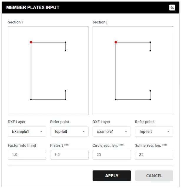
Gegevens van DXF.: Selecteer een DXF-bestand op uw pc. Kies de gewenste laag voor sectie-items. Het referentiepunt bepaalt de oorsprong van de X,j coördinaten. Gebruik de factor om sectiecoördinaten naar millimeters te schalen. Op alle lijnen wordt een standaarddikte toegepast, die later kan worden gewijzigd. Ondersteunde DXF-entiteiten omvatten: Lijnen, Polylijnen, Bogen, en Splines. Voor bogen en splines, De segmentverdeling wordt gespecificeerd zodat deze overeenkomt met de gewenste maaswijdte.
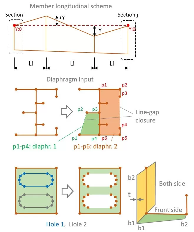
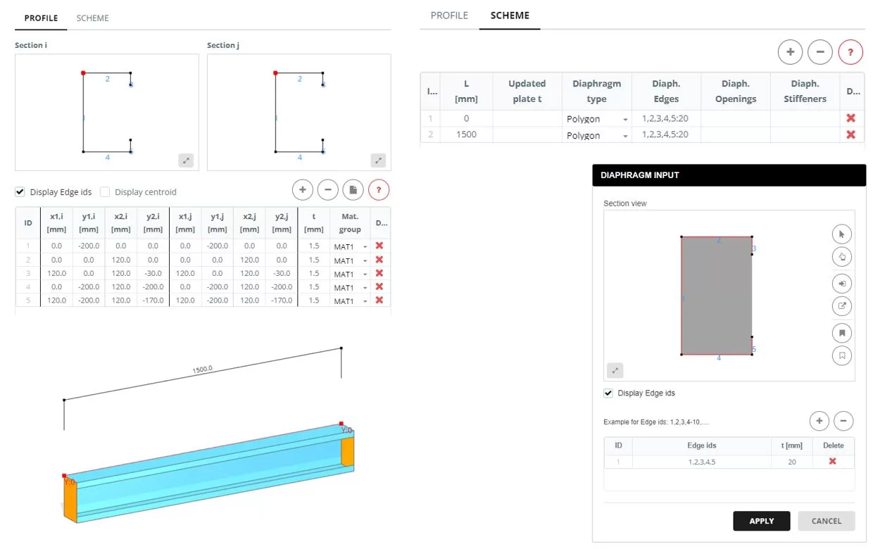
Het gehele onderdeel kan worden weergegeven door een enkele lengte L of door een reeks segmenten Li. Ongeacht het aantal segmenten, de begin- en eindsectielijnen hebben dezelfde coördinaten als gedefinieerd op het tabblad PROFIEL. Elke sectie kan ook een andere Y-positie hebben.
Voor elk segment waar L is niet gelijk aan 0, de dikte voor een groep platen kan worden bijgewerkt in de ‘Bijgewerkte plaat t-kolom’. Enter 0 om de plaat en een waarde groter dan te verbergen 0 om de dikte te wijzigen (t).
Voor segmentsecties, er kan een diafragma worden toegevoegd als de ‘Polygon’ soort is gekozen. Om één of meer diafragma's te specificeren, selecteer de lijnen waaruit de vorm bestaat. Er is slechts één lijnopeningsluiting toegestaan om de vorm te vormen.
Er kunnen ook gaten in het membraan worden aangebracht. Om dit te doen, definieer de gatenvormen door de overeenkomstige lijnen te selecteren die de gaten omsluiten.
Als er een diafragma is gespecificeerd, Vervolgens kunnen flenzen of verstijvers ook worden gedefinieerd door de bijbehorende lijnen te selecteren. Elke flens of verstijver heeft een begin- en eindbreedte (b1,b2), dikte t, en materiaalgroep.
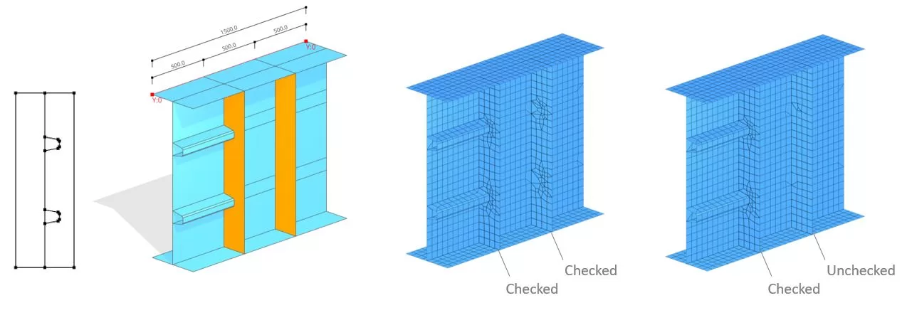
Voorbeeld
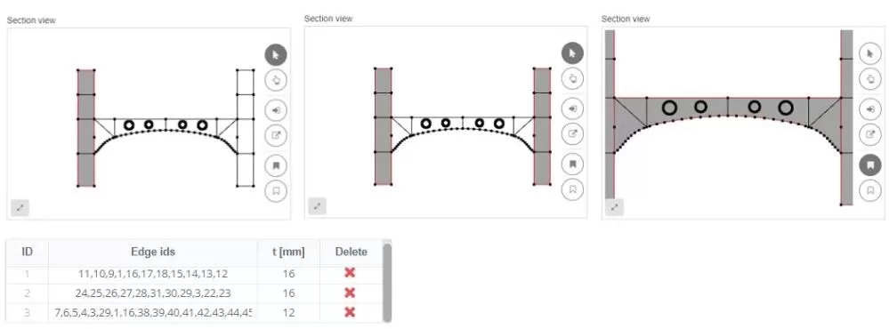
Bij het rangschikken van randen binnen een diafragma, ze kunnen worden meegenomen in het maaspatroon. Bijvoorbeeld, er kan zich een situatie voordoen waarin een longitudinale verstijving wordt verbonden met een verticale verstijver. In dergelijke scenario's, de ‘binnenranden’’ optie moet worden geactiveerd. Echter, als de verticale verstijver nergens aan vastzit, deze optie kan worden uitgeschakeld.