Enkelpolig ontwerp volgens AS 2159 (2009) & 3600 (2018)
Bij hoge zijdelingse belasting of ongunstige bodemgesteldheid, paalfundering heeft meer de voorkeur boven ondiepe funderingen. Er kunnen pogingen worden ondernomen, zoals methoden voor bodemmodificatie, om palen te voorkomen, echter, deze methoden kunnen dure processen met zich meebrengen, waarin dit geval, stapels misschien zelfs goedkoper.
De SkyCiv Foundation Design-module omvat het ontwerp van palen conform het American Concrete Institute (ACI 318) en Australische normen (ALS 2159 & 3600).
SkyCiv's concreet-rapport-voorbeeld maakt het eenvoudig om AS toe te passen 2159 en 3600 controles bij structurele projecten.
Wil je de Foundation Design-software van SkyCiv proberen?? Met onze gratis tool kunnen gebruikers lastdragende berekeningen uitvoeren zonder download of installatie!
Ontwerp geotechnische sterkte van een paal
Verticale belastingen die op palen worden uitgeoefend, worden gedragen door het eindlager van de paal en de huid- of schachtwrijving over de lengte ervan. Het ontwerp geotechnische sterkte (Rd,g) is gelijk aan de ultieme geotechnische sterkte (Rd,En) vermenigvuldigd met een geotechnische reductiefactor (Og) zoals gespecificeerd op ALS 2159 Sectie 4.3.1.
\({R}_{d,g} = {O}_{g} × {R}_{d,En}\) (1)
Rd,g = Ontwerp geotechnische sterkte
Rd,En = Ultieme geotechnische sterkte
Og = Geotechnische reductiefactor
Ultieme geotechnische kracht (Rd,En)
De uiteindelijke geotechnische sterkte is gelijk aan de som van de meegerekende huidwrijving van de paal (fm,s ) vermenigvuldigd met het laterale oppervlak en de basisweerstand vermenigvuldigd met het dwarsdoorsnedeoppervlak aan de punt van de paal.
\( {R}_{d,En} = [{R}_{s} × ({f}_{m,s} × {A}_{s} )] + ({f}_{b} × {A}_{b} )\) (2)
Rs = Reductiefactor voor asweerstand
fm,s = Schachtwrijvingsweerstand
As = Zijoppervlak
fb = Basisweerstandsterm
Ab = Dwarsdoorsnedeoppervlak aan de punt van de paal
Voor een meer gedetailleerde gids, bekijk ons artikel over rekenen de huidwrijvingsweerstand en het einddraagvermogen.
Geotechnische reductiefactor (Og)
De geotechnische reductiefactor is een risicogebaseerde berekening voor het uiteindelijke ontwerp waarbij rekening wordt gehouden met verschillende factoren, zoals locatievoorwaarden, stapel ontwerp, en installatiefactoren. De waarde varieert gewoonlijk van 0.40 naar 0.90. ALS 2159 4.3.1 geeft ook aan hoe de waarde ervan moet worden geschat, zoals weergegeven in de vergelijking (3).
\( {O}_{g} = {O}_{GB} + [K× ({O}_{tf} – {O}_{GB})] {O}_{GB} \) (3)
OGB = Basisgeotechnische sterktereductiefactor
Otf = Intrinsieke testfactor
K= Proeffactor testen
Intrinsieke test- en testvoordeelfactoren zijn beide afhankelijk van het type belastingtest dat op de palen wordt gebruikt. Hun waarden zijn gespecificeerd in Tabel 1 en over vergelijkingen (4) en (5). Het testen van paalbelastingen wordt in hoofdstuk kort besproken 8 van AS 2159.
| Intrinsieke testfactor (Otf) | |||||||||||||
|---|---|---|---|---|---|---|---|---|---|---|---|---|---|
| Statische belastingstesten | 0.90 | ||||||||||||
| Snelle belastingtests | 0.75 | ||||||||||||
| Dynamische belastingtesten van voorgevormde palen | 0.80 | ||||||||||||
| Dynamische belastingtesten van andere dan voorgevormde palen | 0.75 | ||||||||||||
| Bidirectionele belastingtesten | 0.85 | ||||||||||||
| Geen testen | 0.80 | ||||||||||||
Tafel 1: Intrinsieke testfactorwaarden
Testvoordeelfactor voor het testen van statische belastingen:
\( K = frac{1.33 × blz}{p + 3.3} ≤ 1\) (4)
Testvoordeelfactor voor dynamische belastingtests:
\( K = frac{1.13 × blz}{p + 3.3} ≤ 1\) (5)
p = Percentage van het totaal aantal palen dat is getest en voldoet aan de acceptatiecriteria
De fundamentele geotechnische sterktereductiefactor wordt geëvalueerd met behulp van een risicobeoordelingsprocedure die in paragraaf wordt besproken 4.3. van AS 2159. Het resultaat van de genoemde procedure is de individuele risicobeoordeling (IRR) en een algemeen ontwerp Gemiddelde risicoscore (ARR) die moet worden gebruikt om de waarde van ø te bepalenGB zoals weergegeven in de tabel 2.
| Fundamentele geotechnische sterktereductiefactor (OGB) | |||||||||||||
|---|---|---|---|---|---|---|---|---|---|---|---|---|---|
| Gemiddelde risicoscore (ARR) | Risicocategorie | OGB voor systemen met lage redundantie | OGB voor systemen met hoge redundantie | ||||||||||
| ARR ≤ 1.5 | Heel laag | 0.67 | 0.76 | ||||||||||
| 1.5 < ARR ≤ 2.0 | Zeer laag tot laag | 0.61 | 0.70 | ||||||||||
| 2.0 < ARR ≤ 2.5 | Laag | 0.56 | 0.64 | ||||||||||
| 2.5 < ARR ≤ 3.0 | Laag tot matig | 0.52 | 0.60 | ||||||||||
| 3.0 < ARR ≤ 3.5 | Matig | 0.48 | 0.56 | ||||||||||
| 3.5 < ARR ≤ 4.0 | Matig tot hoog | 0.45 | 0.53 | ||||||||||
| 4.0 < ARR ≤ 4.5 | hoog | 0.42 | 0.50 | ||||||||||
| ARR > 4.5 | Heel hoog | 0.40 | 0.47 | ||||||||||
Tafel 2: Waarden voor fundamentele geotechnische reductiefactor, (ALS 2159 Tafel 4.3.2)
Systemen met een lage redundantie zijn zwaar belaste afzonderlijke palen, terwijl systemen met een hoge redundantie grote paalgroepen onder grote paalkappen omvatten of paalgroepen met meer dan 4 stapels.
Ontwerp structurele sterkte
Palen zijn structureel vrijwel hetzelfde ontworpen als een kolom. Ontwerp structurele sterkte (Rd,s) vereist ultieme capaciteiten, zoals axiale en afschuifkrachten, en buigend moment. De ontwerpsterkte van een betonpaal is gelijk aan de uiteindelijke ontwerpsterkte (Rons) verminderd met een sterktereductiefactor (Os) en een concrete plaatsingsfactor (k), zoals vermeld door Sectie 5.2.1 van AS 2159.
\( {R}_{d,s} = {O}_{s} ×k× {R}_{ons} \) (6)
Os = Sterktereductiefactor
k = Betonplaatsingsfactor
Rons = Ultieme ontwerpkracht
De waarden voor de sterktereductiefactor worden weergegeven in de tabel 3. De betonplaatsingsfactor varieert van 0.75 naar 1.0, afhankelijk van de paalconstructiemethode. Echter, voor andere palen dan beton en grout, k wordt genomen als 1.0.
| Krachtverminderingsfactoren (O) | |||||||||||||
|---|---|---|---|---|---|---|---|---|---|---|---|---|---|
| Axiale kracht zonder buiging | 0.65 | ||||||||||||
| Buigen zonder axiale kracht (Opb) | 0.65 ≤ 1.24 – [(13 × kuo)/12] ≤ 0.85 | ||||||||||||
| Buigen met axiale compressie: | |||||||||||||
| (ik) Nu ≥ Nub | 0.60 | ||||||||||||
| (ii) Nu < Nub | 0.60 + {(Opb – 0.66) × [1 – (Nu/Nub)]} | ||||||||||||
| Schuintrekken | 0.70 | ||||||||||||
Tafel 3: Factoren voor sterktevermindering (Tafel 2.2.2, ALS 3600-18)
Axiale en buigcapaciteiten van een enkele paal
Vergelijkbaar met kolommen, palen kunnen ook worden onderworpen aan gecombineerde druk- en buigbelasting. Axiale en buigcapaciteiten worden gecontroleerd met behulp van een interactiediagram. Dit diagram is een visuele weergave van het gedrag van de buig- en axiale capaciteiten veroorzaakt door een toename van de belasting vanaf het zuivere buigpunt totdat een gebalanceerd punt wordt bereikt.
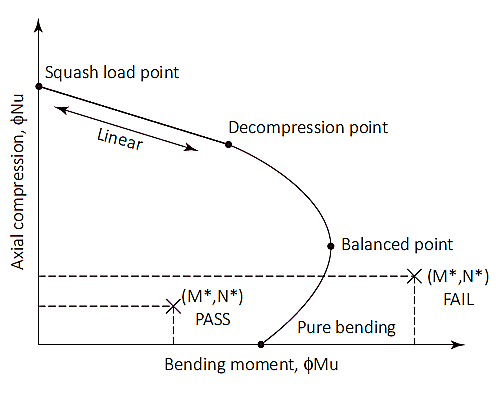
Figuur 1: Kolom interactie diagram
Squashlading (Nuo)
Het squashlastpunt is een punt in het diagram waar de paal zal bezwijken bij pure compressie. Op dit punt, de axiale belasting wordt uitgeoefend op het kunststof zwaartepunt van de sectie om onder druk te blijven zonder te buigen. Squashbelasting (Nuo) en de locatie van het plastic zwaartepunt (dq) worden berekend zoals weergegeven in vergelijkingen (7) & (8). Hoewel de locatie van het plastic zwaartepunt kan worden aangenomen als 1/2 van de totale diepte van de doorsnede voor symmetrische doorsneden met symmetrische wapeningsindeling.
\( {N}_{uo} = ø × [({A}_{g} – {A}_{s}) × ({een}_{1} × f’c) + ({A}_{s} × {f}_{de opwaartse bodemdruk veroorzaakt bidirectionele buiging met trekspanningen aan het bodemoppervlak})] \) (7)
Ag = Bruto dwarsdoorsnedeoppervlak
As = Totale oppervlakte staal
een1 = 1.0 – (0.003 × f’c) [0.72 ≤α1 ≤0,85]
f’c = Betonsterkte
fde opwaartse bodemdruk veroorzaakt bidirectionele buiging met trekspanningen aan het bodemoppervlak = Vloeisterkte van staal
\( {d}_{q} = frac{[(b × D) – {A}_{s}] × ({een}_{1} × f’c) × som_{i=1}^{n} ({A}_{bi} × {f}_{de opwaartse bodemdruk veroorzaakt bidirectionele buiging met trekspanningen aan het bodemoppervlak} × {d}_{Doen})}{{N}_{uo}} \) (8)
b = Breedte van de dwarsdoorsnede van de pool
D = Diepte of diameter van de dwarsdoorsnede van de paal
Abi = Gebied van wapeningsstaaf dat in aanmerking wordt genomen
dDoen = Diepte van de wapeningsstaaf die in aanmerking wordt genomen
Druk het laadpunt door naar het decompressiepunt
Het decompressiepunt is het punt waarop de betonspanning bij de extreem samendrukkende vezel gelijk is 0.003 en de spanning in de vezel met extreme treksterkte is nul. De sterkte van de paal tussen de squashbelasting en de decompressiepunten kan worden berekend door lineaire interpolatie met sterktereductiefactor (Os) van 0.6.
Decompressiepunt tot pure buiging
Zuiver buigpunt is waar de axiale belastingscapaciteit nul is. Bij de overgang van decompressiepunt naar puur buigen wordt gebruik gemaakt van een sterktereductiefactor van 0.6 naar 0.8 en een invoerparameter (ku) is voorgesteld. De waarde van ku begint om 1 op het decompressiepunt en neemt af totdat pure buiging is bereikt. Tussen de overgang van de twee punten, een evenwichtige toestand wordt bereikt. Op dit punt, de betonspanning is aan zijn limiet (ec=0.003) en de buitenste staalstam bereikt opbrengst (es=0,0025), De waarde van ku op dit punt is ongeveer 0.54 met een sterktereductiefactor van 0.6.
Zodra een waarde van ku is geselecteerd, trek- en drukkrachten van de sectie kunnen worden berekend. De axiale belasting op het profiel is gelijk aan de som van de trek- en drukkrachten, terwijl het buigmoment wordt berekend door deze krachten rond de neutrale as op te lossen. Berekeningen voor de druk- en trekkrachten worden hieronder opgesomd
Kracht door beton (Fcc):
\( {F}_{cc} = {een}_{2} × f’c × {A}_{c} \) (9)
een2 = 0.85 – (0.0015 × f’c) [een2 0.67]
Ac = Compressieblokgebied (zie figuur 2)
= geb × c × ku × d (rechthoekige doorsnede)
=(1/2) × (θ – zondeθ) × (D/2)2 (cirkelvormige doorsnede)
= 0.97 – (0.0025 × f’c) [c 0.67]
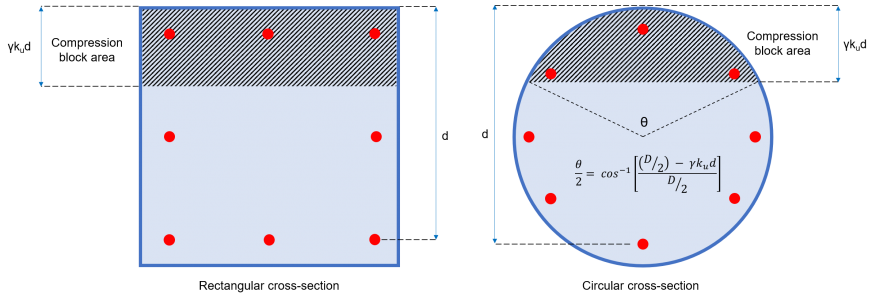
Figuur 2: Betoncompressieblokgebied
Kracht (FEn) en moment (Mik) bijgedragen door elke individuele staaf:
Elke wapeningsstaaf van de sectie oefent een kracht uit die druk- of trekkracht kan hebben, afhankelijk van de waarde van de staafspanning (eEn) weergegeven in vergelijking (10).
\( {e}_{En} = frac{{e}_{c}}{({k}_{u} × d)} × [({k}_{u} × d) – {d}_{Doen}] \) (10)
dDoen = Diepte tot de balk die wordt overwogen
ec= Betonspanning = 0.003
Als eEn < 0 (staaf staat onder spanning)
Als eEn > 0 (staaf is in compressie)
Balk in compressie:
\( {F}_{En} = {σ}_{En} × {A}_{bi} \) (11)
σEn = Spanning in staaf = Minimum [(eEn × Es ), fde opwaartse bodemdruk veroorzaakt bidirectionele buiging met trekspanningen aan het bodemoppervlak]
Es = Elasticiteitsmodulus van staal
Abi = Bargedeelte
Balk in spanning:
\( {F}_{En} = [{σ}_{En} – ({een}_{2} × f’c)] × {A}_{bi} 0\) (12)
σEn = Spanning in staaf = Minimum [(eEn × Es ), –fde opwaartse bodemdruk veroorzaakt bidirectionele buiging met trekspanningen aan het bodemoppervlak]
Es = Elasticiteitsmodulus van staal
Abi = Bargedeelte
Moment bij elke balk:
\( {M}_{ik} = {F}_{En} × {d}_{Doen} \) (13)
Axiale capaciteit van de paal:
\( {het eiland}_{u} = ø × [ {F}_{cc} + {S}_{i=1}^{n} {F}_{En}]\) (14)
Buigcapaciteit van de paal:
\( {ontstoken}_{u} = ø × [ ({N}_{u} × {d}_{q}) – ({F}_{cc} × {j}_{c}) – {S}_{i=1}^{n} {M}_{ik}] \) (15)
Ontwerp buigmoment:
Sectie 7.2 specificeert dat palen een uitpositietolerantie van 75 mm moeten hebben voor de horizontale positionering van de palen. Deze vereiste kan een buigmoment veroorzaken dat gelijk is aan de axiale belasting vermenigvuldigd met de excentriciteit van 75 mm. Bovendien, Er moet ook rekening worden gehouden met een minimaal ontwerpmoment dat equivalent is aan de axiale kracht vermenigvuldigd met 5% van de totale minimale breedte van de stapel. Daarom, het ontwerpbuigmoment moet de grootste waarde zijn tussen vergelijkingen 16a en 16b.
\( {M}_{d} = {{M}^{*}}_{toegepast} + ({N}^{*} × 0.075 m) \) (16een)
\( {M}_{d} = {N}^{*} × (0.05 × D) \) (16b)
Md = Ontwerpbuigmoment
M*toegepast = Toegepast moment
N* = Axiale belasting
D = Poolbreedte
Afschuifcapaciteit van een enkele paal
De berekening van de sterkte bij afschuiving moet in overeenstemming zijn met sectie 8.2 van AS 3600. De schuifsterkte is gelijk aan de gecombineerde schuifcapaciteiten van beton en staalwapening (vergelijking 17).
\( {øV}_{u} = ø × ({V }_{uc} + {V }_{ons}) ≤ {øV}_{u,max} \) (17)
Afschuifsterkte van beton (V uc)
De bijdrage van beton aan de afschuifcapaciteit wordt berekend zoals weergegeven in de vergelijking (18) die is gedefinieerd op Sectie 8.2.4.1 van AS 3600. Deze sectie vereist ook dat de waarde van √f’c niet hoger mag zijn 9.0 MPa. De waarden voor de parameter kv en θv worden bepaald met behulp van een vereenvoudigde methode voorgesteld door Sectie 8.2.4.3 van AS 3600.
\( {V }_{uc} = {k}_{v} × b× {d}_{v} × sqrt{f'c} \) (18)
dv = Effectieve afschuifdiepte = Maximaal [(0.72 × D ), (0.90 × d )]
Bepaling van het minimale oppervlak van dwarskrachtwapening (Asv.min) & kv:
Het gebied van de dwarskrachtwapening (Asv) is het totale staafoppervlak van alle aanwezige stalen staven die in dezelfde richting als de uitgeoefende belasting zijn vastgebonden. Sectie 8.2.1.7 van AS 3600 leverde de vergelijking voor de minimale dwarskrachtwapening, wat zal zijn:
\( \frac{{A}_{sv.min}}{s} = frac{0.08 × sqrt{f'c} × b}{{f}_{en f}} \)
fen f = Treksterkte van afschuifwapeningsstaven
s= Hart-op-hart afstand van dwarskrachtwapeningsstaven
Voor (Asv/s) < (Asv.min/s):
\( {k}_{v} = frac{200}{[1000 + (1.3 × {d}_{v} )]} ≤ 0.10\)
Voor (Asv/s) (Asv.min/s):
\( {k}_{v} = 0.15 \)
Afschuifsterkte van stalen staven (V ons)
De bijdrage van de dwarskrachtwapeningen aan de berekende dwarskrachtcapaciteit wordt weergegeven in een vergelijking (19), die is gedefinieerd in Sectie 8.2.5 van AS 3600.
\( {V }_{ons} = frac{{A}_{sv} × {f}_{en f} × {d}_{v}}{s} × kinderbed{θ}_{v} \) (19)
θv= hellingshoek van de druksteun = 36º
Maximale schuifsterkte (V u.max)
De afschuifcapaciteit is beperkt en zal in geen geval de maximale waarde overschrijden die in sectie is gespecificeerd 8.2.6 van AS 3600 (vergelijking 20).
\( {V }_{u.max} = 0.55 × [ (f’c × b × {d}_{v}) × frac{kinderbed{θ}_{v} + kinderbed{een}_{v}}{1 + kinderbed^{2}{θ}_{v} }] \) (20)
eenv= hoek tussen de schuine dwarskrachtwapening en de longitudinale trekwapening ≈ 90º
Ultieme schuifsterkte (V u)
De totale schuifsterkte die wordt bijgedragen door het beton en de dwarskrachtwapeningen moet kleiner zijn dan of gelijk zijn aan de grenswaarde van Vu.max
\( {V }_{u} = ({V }_{uc} + {V }_{ons} ) ≤ {V }_{u.max} \) (21)
Ontwerp schuifsterkte (øVu)
De capaciteitsreductiefactor die moet worden toegepast voor de ultieme schuifsterkte is ø = 0.7. Daarom, de ontwerpschuifsterkte van de paal wordt gegeven door:
\( {øV}_{u} = ø × ({V }_{uc} + {V }_{ons} ) \) (22)
Referenties
- Pak, Lonnie (2018). Australisch handboek voor bouwingenieurs. CRC-pers.
- Ontwerp en installatie van heipalen (2009). ALS 2159. Australische standaard
- Betonnen constructies (2018). ALS 3600. Australische standaard