Wat is een excentrische belasting?
Een excentrische belasting is elke belasting niet toegepast op het zwaartepunt van het lid. In eindige elementenanalyse, puntbelastingen, verdeelde ladingen, en andere krachten worden over het algemeen uitgeoefend op het zwaartepunt van de sectie (d.w.z. het geometrische middelpunt van de sectie). Echter, in bepaalde scenario's wil je misschien een kracht uit het midden uitoefenen – bijvoorbeeld, het uitoefenen van een belasting op de flens van een I-balk, in plaats van het internet. Ervan uitgaande dat dit een zijdelingse belasting is, dit zal een torsiekracht en een algeheel ander belastingsgedrag in het element veroorzaken.
Hoe excentrische belastingen op een model toe te passen
Hier laten we u een voorbeeld zien van hoe u dit kunt gebruiken Stijve links om een dergelijke excentrische belasting uit te oefenen. Door gebruik te maken van starre koppelingen, we kunnen de belasting van het zwaartepunt van de staaf naar een andere locatie overbrengen. Stijve links zijn uiterst nuttig voor dit soort werk, omdat het automatisch het resulterende moment en andere krachten van de ene locatie naar de andere berekent.
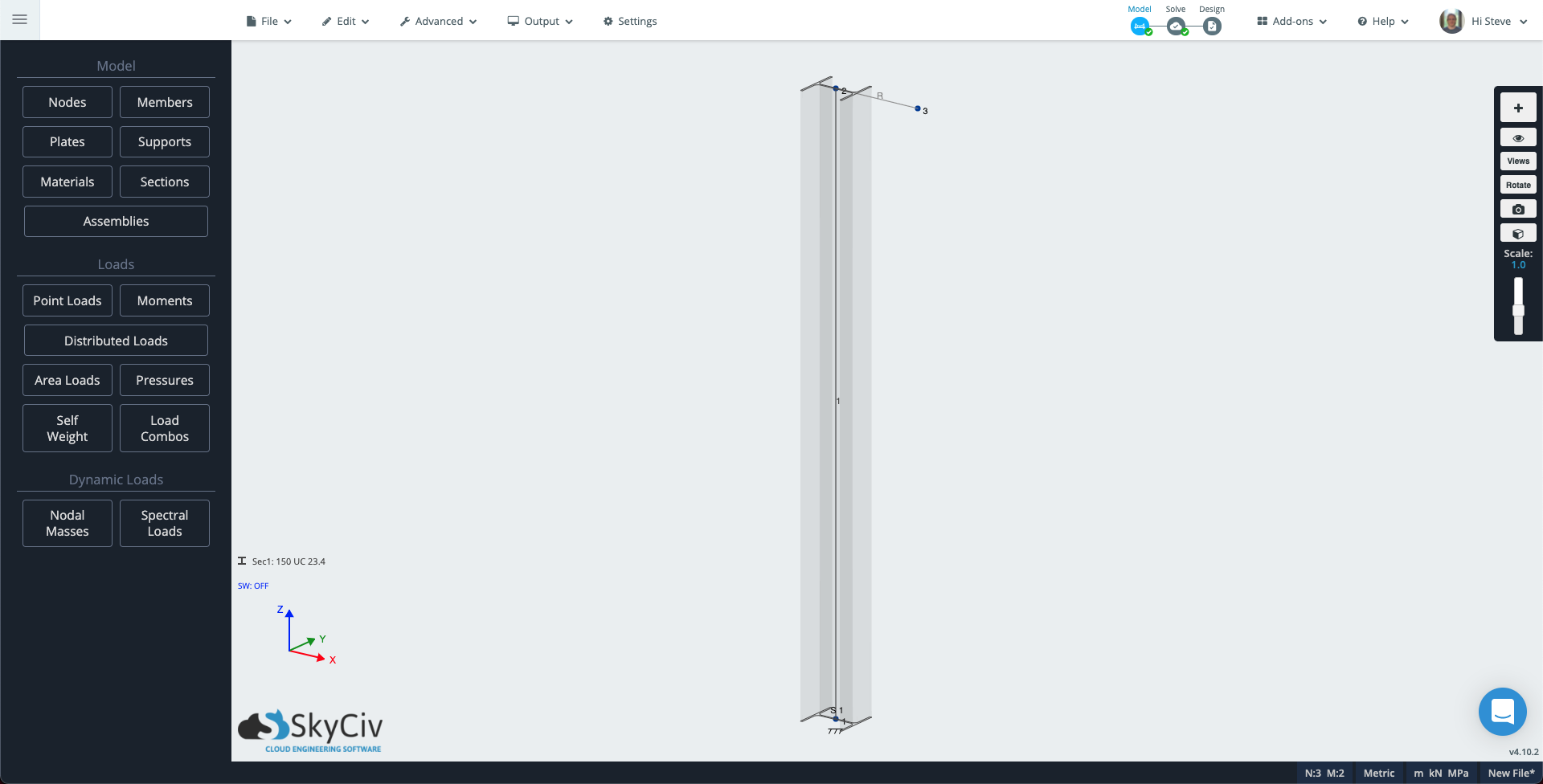
Ga naar S3D en maak een nieuw model. De volgende, selecteer het pengereedschap in het rechterpaneel of door erop te tikken V . Klik eenmaal om het eerste knooppunt op de oorsprong te plaatsen, Trek vervolgens ongeveer 2 meter omhoog (6.5ft) om een kolom te maken.
Beneden in de hoek, bij het coördinatensysteem, Klik Sec1: Niet gedefinieerd, en vervolgens in het linkerpaneel, Klik Bouwer om sectiebouwer te openen. Kies een kolomsectie, voor deze tech-note heb ik een Australische 150UC23.4 geselecteerd, dit is ongeveer een 6×6 Ik sectie voor onze keizerlijke vrienden. In het linkerpaneel, klik op ondersteuningen en voeg vaste ondersteuning toe bij Node 1.
Nu zullen we nog een lid toevoegen, zodat we een excentrische belasting kunnen creëren die torsie veroorzaakt, en een andere die een knikeffect op onze kolom creëert.
Om de oriëntatie van uw kolom te zien, klik op het zichtbaarheidspictogram in het rechterpaneel en selecteer 3D Leden. Gebruik het pengereedschap om een 300 mm te tekenen (1ft) lid in de X-richting vanaf de bovenkant van de kolom. kan worden aangenomen dat “3D-lid” is ingeschakeld, je zult zien dat dit lid de kolomsectie gebruikt. Klik op het nieuwe lid, en vervolgens in het linkerpaneel, verander het type attribuut naar Stijf en klik Van toepassing zijn.
Uw model zou er ongeveer zo uit moeten zien als hieronder:
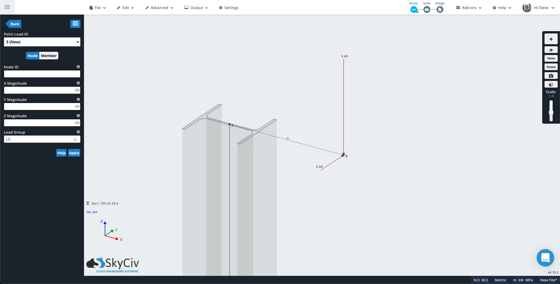
Klik op Puntbelastingen in het linkerpaneel. Vul de attributen in met de volgende waarden:
- Puntbelastingen zijn krachten die kunnen worden uitgeoefend op een knoop of op een punt samen met een staaf: 3
- Puntbelastingen zijn krachten die kunnen worden uitgeoefend op een knoop of op een punt samen met een staaf: -5 (Als uw model de Y-as als verticaal gebruikt, voeg deze waarde in plaats daarvan toe aan Y Magnitude).
- Groep laden: Knikbelasting
Klik op toepassen en de puntlast wordt aan het model toegevoegd. De Puntlast-ID wordt verhoogd naar 2 (Nieuw) voeg dus nog een belasting toe om torsie in de kolom te creëren:
- Puntbelastingen zijn krachten die kunnen worden uitgeoefend op een knoop of op een punt samen met een staaf: 3
- Puntbelastingen zijn krachten die kunnen worden uitgeoefend op een knoop of op een punt samen met een staaf: 2 (Als uw model de Y-as als verticaal gebruikt, voeg deze waarde in plaats daarvan toe aan Z Magnitude).
- Groep laden: Torsiebelasting
Knooppunt 3 van uw model zou er nu ongeveer als volgt uit moeten zien.
Voer de oplosser uit, open vervolgens de rendermodus – het kubuspictogram in het rechterpaneel. Wijzig de vervolgkeuzelijst in het linkerpaneel in Knikbelasting, de doorbuigingsschaal naar Auto, en de vervolgkeuzelijst Ledenresultaten naar Verplaatsingssom. Je kunt nu zien hoe de eerste excentrische belasting een knikeffect veroorzaakt.
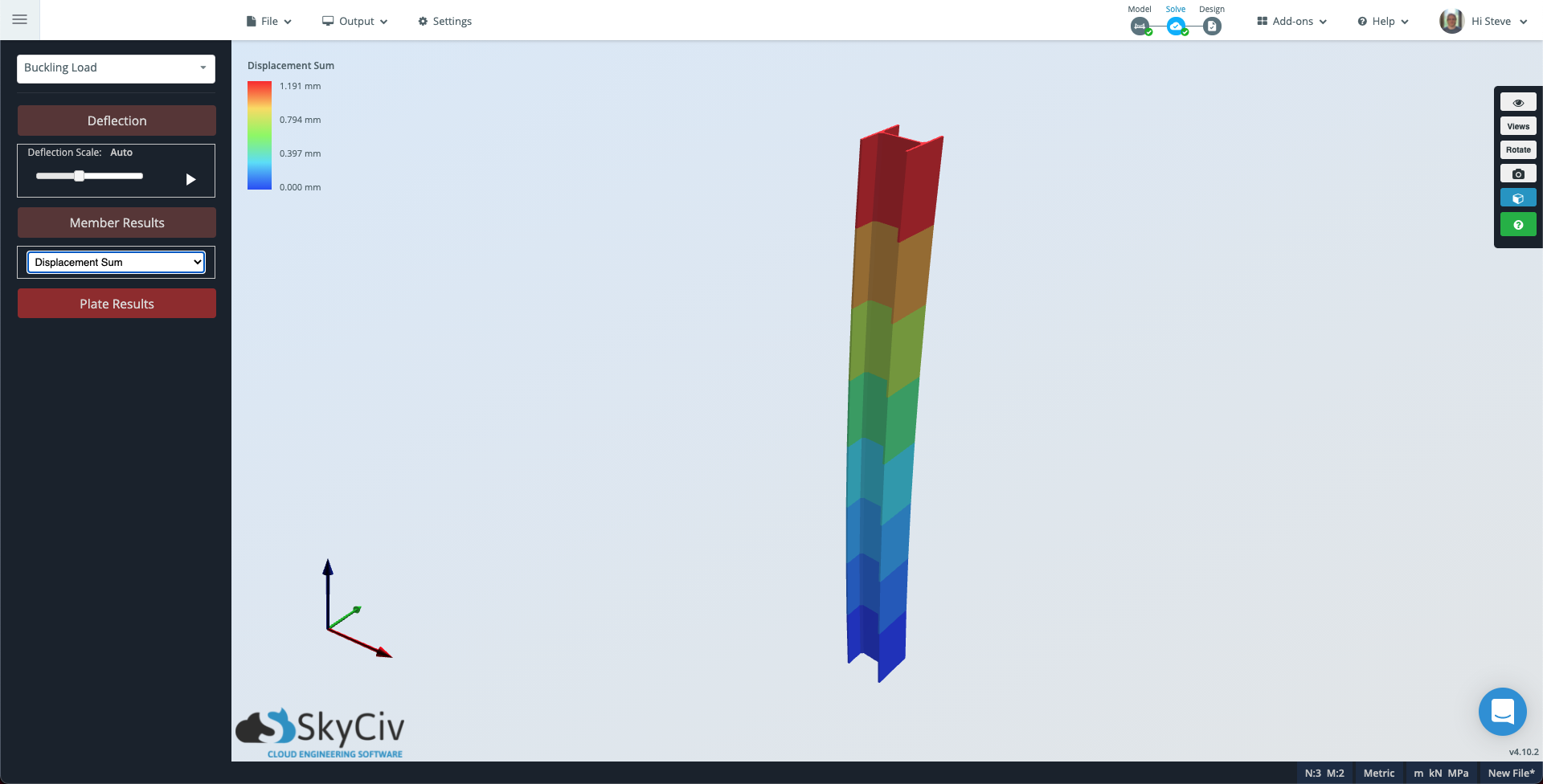
Merk op dat als u een fijnere onderverdeling van het lid wilt zien, u daar naartoe kunt gaan Instellingen Draai de weergave zodat u eenvoudig de twee gemeenschappelijke spanten kunt selecteren met een selectie van links naar rechts Oplosser, verander de Evaluatiepunten per lid naar een geschikt nummer en voer solve opnieuw uit.
Verander nu de vervolgkeuzelijst van Knikbelasting naar Torsiebelasting als de Ledenresultaten naar Torsiespanning. In dit geval, de staaf zal grijs lijken omdat de torsiebelasting overal op de staaf consistent is.
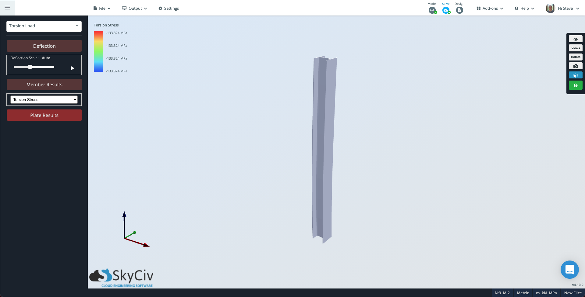
Merk op dat de contourschaal linksboven nog steeds de omvang van de torsie weergeeft die de kolom ervaart.