In dit artikel worden twee ontwerpvoorbeelden van gewapend betonplaten besproken, inclusief een- en tweezijdig buigen. Het belangrijkste doel is om de resultaten te vergelijken die zijn verkregen tussen handmatige berekeningen en de SkyCiv Plate Design Module. Wij zullen Eurocode gebruiken 2 voor constructies van gewapend beton.
Constructiecodes hebben vergelijkbare benaderingen bij het definiëren van de typische gevallen voor platen. Als je wat meer wilt weten over dit onderwerp, we raden u aan de volgende artikelen over plaatontwerp te lezen ACI Slab Design Voorbeeld en vergelijking met SkyCiv en Australische normen AS3600 Slab Design Voorbeeld en vergelijking met SkyCiv
Ontwerpvoorbeeld van eenrichtingsplaat
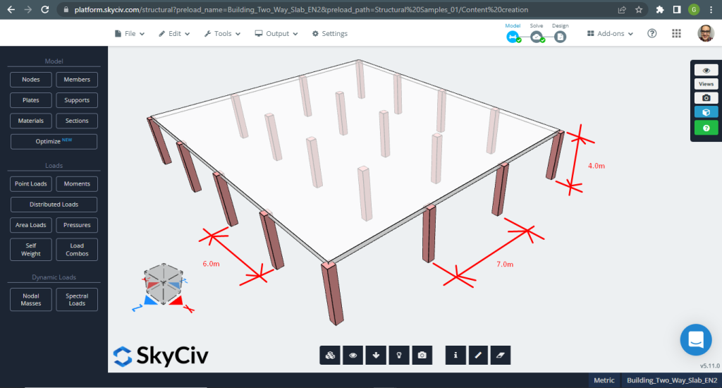
Het eerste geval dat moet worden geanalyseerd, is een klein gebouw van één verdieping (Figuur 1, Figuur 2) die een plaatgedrag heeft dat wordt beschreven als in één richting.
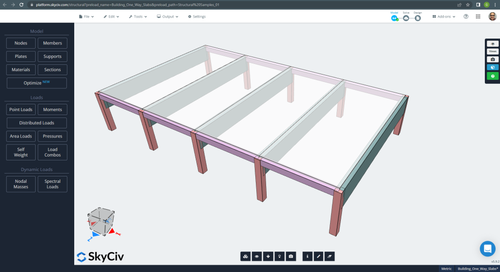
Figuur 1. Eenrichtingsplaten in een klein bouwvoorbeeld. (Structurele 3D, SkyCiv Cloud-engineering).
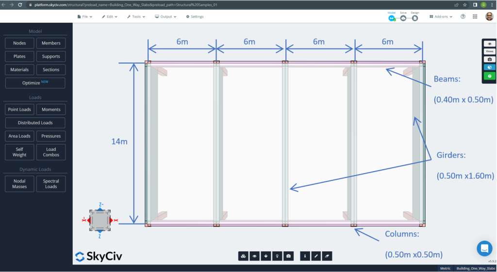
Figuur 2. Eenrichtingsplaten in een klein bouwvoorbeeld (afmetingen plannen). (Structurele 3D, SkyCiv Cloud-engineering).
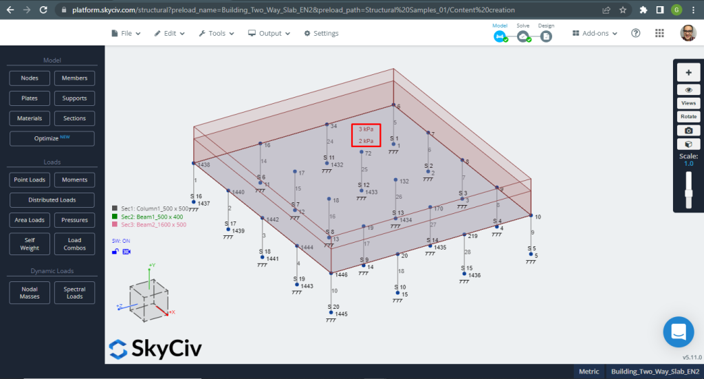
Voor het plaatvoorbeeld, samengevat, het materiaal, elementen eigenschappen, en veel om over na te denken :
- Classificatie van plaattypes: Een – manier gedrag \(\frac{L_2}{L_1} > 2 ; \frac{14m}{6m}=2,33 > 2.00 \) OK!
- Bezetting gebouw: Residentieel gebruik
- Plaatdikte \(t_{plaat}=0,25m)
- Dichtheid van gewapend beton \(\rho_w = 25 \frac{kN}{m^3}\)
- Beton karakteristieke druksterkte bij 28 dagen (C25\30) \(fck = 25 MPa \)
- Eigen gewicht van plaat \(Dead = \rho_w \times t_{plaat} = 25 \frac{kN}{m^3} \maal 0,25m= 6.25 \frac {kN}{m^2}\)
- Superopgelegde eigen last \(SD = 3.0 \frac {kN}{m^2}\)
- Live laden \(L = 2.0 \frac {kN}{m^2}\)
Handberekeningen volgens EN-2
In deze sectie, wij berekenen de benodigde gewapende stalen wapening met behulp van de referentie van de Eurocode-norm. We verkrijgen eerst het totale meegerekende buigmoment dat moet worden uitgevoerd door de strook met eenheidsbreedte van de plaat.
- Dode lading, \(g = (3.0 + 6.25) \frac{kN}{m^2} \keer 1 m = 9.25 \frac{kN}{m}\)
- Live laden, \(q = (2.0) \frac{kN}{m^2} \keer 1 m = 2.0 \frac{kN}{m}\)
- Ultieme lading, \(Fd = 1,35maal g + 1.5\keer q = (1.35\keer 9.25 + 1.5\keer 2.0)\frac{kN}{m} =15,5 frac{kN}{m} \)
Voordat u het stalen wapeningsgebied verkrijgt, we moeten de span-effectieve diepteverhoudingen controleren. Twee hoofdzaken:
| Structureel systeem | Basis overspanning-effectieve diepteverhouding | ||
|---|---|---|---|
| Factor voor structuursysteem K | Beton zwaar belast %(\(\rho = 1.5 )\) | Beton licht belast %(\(\rho = 0.5 )\) | |
| 1. Eindoverspanning van een doorlopende ligger of eenrichtingsdoorlopende plaat of tweerichtingsplaat doorlopend over één lange zijde | 1.3 | 18 | 26 |
| 2. Binnenoverspanning van een doorlopende ligger of eenzijdig of tweezijdig overspannende plaat | 1.5 | 20 | 30 |
Het meest kritieke geval betreft nummer één, Dus, we selecteren een verhouding van 26.
- \(t_{min}= frac{L}{IK WEET}+dekking+0,5puntbalk_{diameter}= frac{6m}{26}+0.025m+0,5maal 12 mm=0,26 m \) ~ \(0.25[object Window]). De totale dikte is nog steeds voldoende, OK!
Nu, het is tijd om de tafel te gebruiken voor doorlopende platen in één richting:
| Einde ondersteuningsvoorwaarde | In eerste instantie interieurondersteuning | In het midden van de binnenoverspanningen | Bij binnensteunen | ||||
|---|---|---|---|---|---|---|---|
| Vastgezet | Continu | ||||||
| Externe ondersteuning | Dichtbij het midden van de eindoverspanning | Einde ondersteuning | Eindspanwijdte | ||||
| Moment | 0 | 0.086FL | – | 0.075FL | – | 0.063FL | – |
| 0.04FL | 0.086FL | 0.063FL | |||||
| Schuintrekken | 0.4F | – | – | – | |||
| 0.46F | 0.6F | 0.5F | |||||
Waarbij:
- L is de effectieve overspanning
- F is de totale ultieme belasting in de overspanning (1.35Gk + 1.5Qk; Gk is de eigen last en Qk de levende last, respectievelijk)
Er zal slechts één geval worden uitgelegd (continue eindondersteuning) en de rest wordt weergegeven in de volgende tabel.
- \(F=Fdmaal L = 15.5 \frac{kN}{m} \maal 6m= 93.0 kN \)
- \(M=0,04FL=0,04 tijden 93.0 kN maal 6m= -22.32{kN}{m}\)
- \(d = 230 mm \)
- \(K=frac{M}{{b}{d^2}{f_{zodat ingenieurs precies kunnen nagaan hoe deze berekeningen zijn gemaakt}}}= frac{22.32\maal 10^6 {N}{mm}}{{1000mm}\keer{(230 mm)^ 2}\keer {25 \frac{N}{mm^2}}}=0,016877)
- \(l_a = 0.95 \)
- \(z=l_a \times d = 0.95\times 230mm = 218.50 mm\)
- \(A_s = frac{M}{{0.87}{f_{ja}}{z}}= frac{22.32\maal 10^6 {N}{mm}}{0.87\keer 500 {N}{mm^2} \keer {218.50mm} = 234.83 mm^2 }\)
- \(EEN_{s,min}=0,0013{b}{d}=0.0013\times 1000mm \times 230 mm =299 mm^2\)
- \(EEN_{de opwaartse bodemdruk veroorzaakt bidirectionele buiging met trekspanningen aan het bodemoppervlak}=max(Als, EEN_{s,min}) = max(234.83, 299) mm^2 = 299 mm^2 \)
| Momenten | Exterieur Negatief Links | Exterieur Positief | Exterieur negatief recht | Binnenlands Negatief Links | Interieur Positief | Binnenlands negatief recht |
|---|---|---|---|---|---|---|
| M-waarde, kN-m | 22.32 | 35.15 | 41.85 | 48.00 | 35.15 | 35.15 |
| K | 0.0168 | 0.0266 | 0.03164 | 0.0362 | 0.0266 | 0.0266 |
| z, mm | 218.50 | 218.50 | 218.50 | 218.50 | 218.50 | 218.50 |
| \(Als, mm^2\) | 234.83 | 369.815 | 440.31 | 505.011 | 369.815 | 369.815 |
| \(EEN_{s,min},mm^2\) | 299.00 | 299.00 | 299.00 | 299.00 | 299.00 | 299.00 |
| \(EEN_{de opwaartse bodemdruk veroorzaakt bidirectionele buiging met trekspanningen aan het bodemoppervlak} {mm^2}\) | 299.00 | 369.815 | 440.31 | 505.011 | 369.815 | 369.815 |
De volgende stap is het berekenen van het wapeningsstaal met behulp van de Plate Design Module in SkyCiv. Alstublieft, blijf het volgende gedeelte lezen!.
Als je nieuw bent bij SkyCiv, Meld u aan en test de software zelf!
Resultaten van de SkyCiv S3D-plaatontwerpmodule
In dit gedeelte wordt het verkrijgen van het staalversterkingsgebied behandeld, maar alleen met behulp van de software, de Plaatontwerpmodule. Op een beknopte manier, we tonen de resultaten of belangrijke informatie alleen via afbeeldingen.
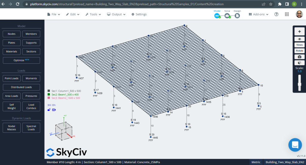
Voordat u het model analyseert, we moeten een plaatmaaswijdte definiëren. Enkele referenties (2) adviseer een maat voor het schaalelement van 1/6 van de korte overspanning of 1/8 van de lange spanwijdte, hoe korter. Deze waarde volgen, wij hebben \(\frac{L2}{6}= frac{6m}{6} = 1 meter \) of \(\frac{L1}{8}= frac{14m}{8}=1,75m \); wij nemen 1m als maximale aanbevolen maat en 0,50m toegepaste maaswijdte.
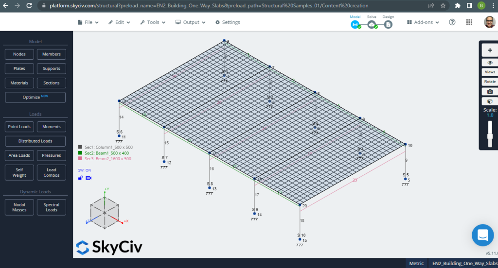
Figuur 3. Plaat met mazen. (Structurele 3D, SkyCiv Cloud-engineering).
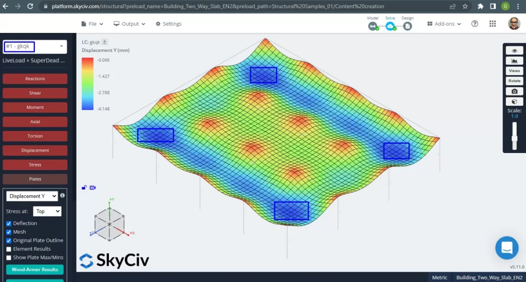
Ooit hebben we ons analytisch structureel model verbeterd, we voeren een lineair-elastische analyse uit. Bij het ontwerpen van platen, we moeten controleren of de verticale verplaatsing kleiner is dan het maximum toegestaan door de code. Eurocode 2 heeft een maximale verticale verplaatsing van onderhoud gerealiseerd van \(\frac{L}{250}= frac{6000mm}{250}=24.0 mm\).
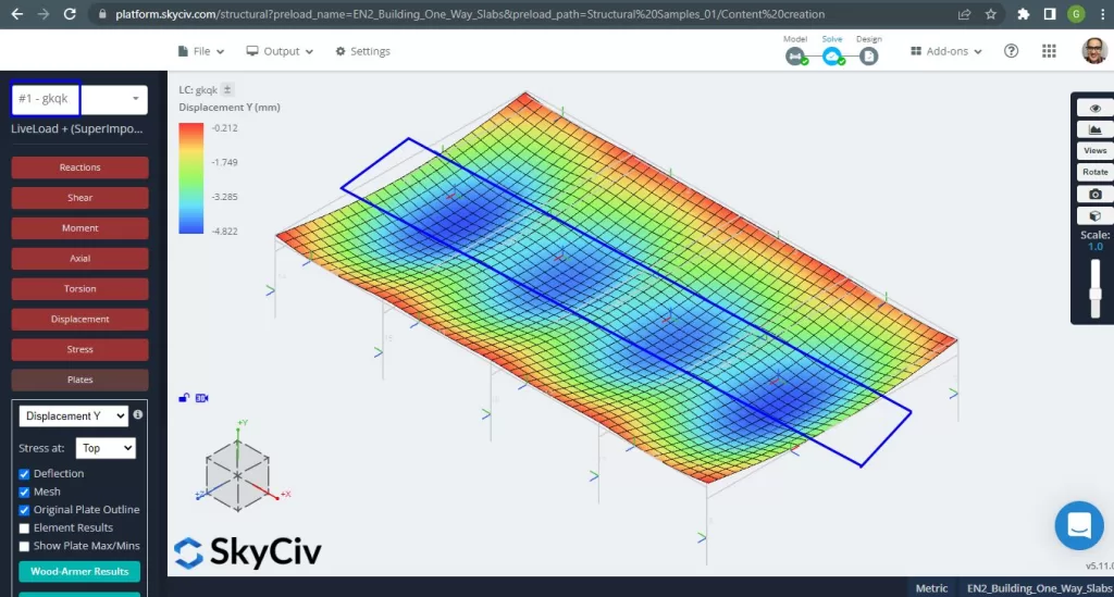
Figuur 4. Verticale verplaatsing, maximale waarden in het midden van de overspanningen. (Structurele 3D, SkyCiv Cloud-engineering).
Vergelijking van de maximale verticale verplaatsing met de code-referentiewaarde, de stijfheid van de plaat is voldoende. \(4.822 mm < 24.00mm\).
De maximale momenten in de overspanningen van de plaat bevinden zich voor positief in het midden en voor negatief aan de buiten- en binnensteunen. Laten we deze momentenwaarden bekijken in de volgende afbeeldingen.
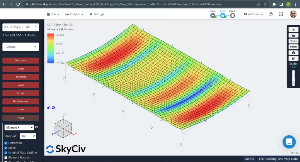
Figuur 5. Buigmomenten in X-richting. (Structurele 3D, SkyCiv Cloud-engineering).

Figuur 6. Buigmomenten in Y-richting. (Structurele 3D, SkyCiv Cloud-engineering).
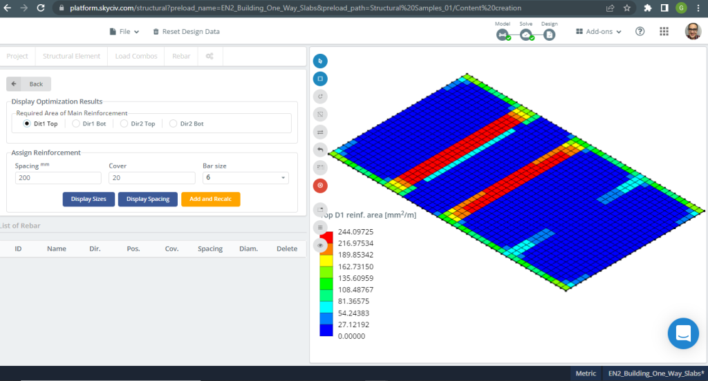
Figuur 7. Stalen versterking voor richting X bovenaan. (Structurele 3D, SkyCiv Cloud-engineering).
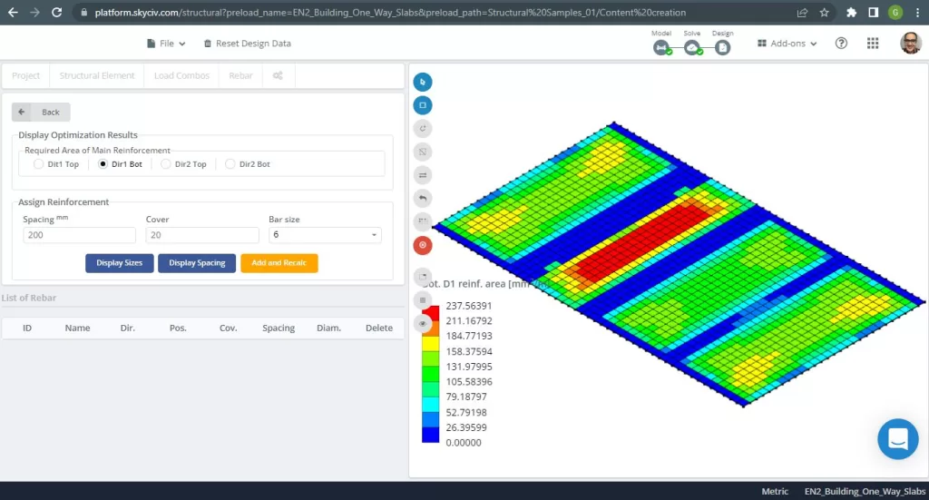
Figuur 8. Stalen versterking voor richting X aan de onderkant. (Structurele 3D, SkyCiv Cloud-engineering).

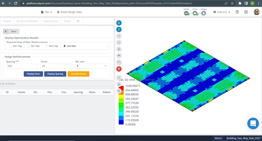
Figuur 9. Stalen versterking voor richting Y bovenaan. (Structurele 3D, SkyCiv Cloud-engineering).
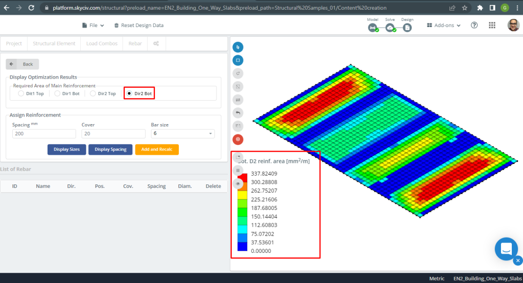
Figuur 10. Stalen versterking voor richting Y aan de onderkant. (Structurele 3D, SkyCiv Cloud-engineering).
Vergelijking van resultaten
De laatste stap in dit ontwerpvoorbeeld van een eenrichtingsplaat is het vergelijken van het gebied van de stalen wapening verkregen door S3D-analyse (lokale assen “2”) en handberekeningen.
| Momenten en staalgebied | Exterieur Negatief Links | Exterieur Positief | Exterieur negatief recht | Binnenlands Negatief Links | Interieur Positief | Binnenlands negatief recht |
|---|---|---|---|---|---|---|
| \(EEN_{de opwaartse bodemdruk veroorzaakt bidirectionele buiging met trekspanningen aan het bodemoppervlak, HandCalcs} {mm^2}\) | 299.00 | 369.82 | 440.31 | 505.011 | 369.82 | 369.82 |
| \(EEN_{de opwaartse bodemdruk veroorzaakt bidirectionele buiging met trekspanningen aan het bodemoppervlak, S3D} {mm^2}\) | 308.41 | 337.82 | 462.61 | 462.61 | 262.75 | 308.41 |
| \(\Delta_{verschil}\) (%) | 3.051 | 8.653 | 4.820 | 8.400 | 28.95 | 16.610 |
We kunnen zien dat de resultaten van de waarden zeer dicht bij elkaar liggen. Dit betekent dat de berekeningen correct zijn!
Als je nieuw bent bij SkyCiv, Meld u aan en test de software zelf!
Ontwerpvoorbeeld van tweerichtingsplaten
SkyCiv 3D Plate Design Module is krachtige software die elk type gebouw dat u in beeld kunt brengen, kan analyseren en ontwerpen. Voor het tweede ontwerpplaatvoorbeeld, we hebben besloten om een vlakplaatsysteem te gebruiken (figuur 11).
Figuur 11. Eenrichtingsplaten in een klein bouwvoorbeeld. (Structurele 3D, SkyCiv Cloud-engineering).
Voor het plaatvoorbeeld, samengevat, het materiaal, elementen eigenschappen, en veel om over na te denken :
- Classificatie van plaattypes: Twee – manier gedrag \(\frac{L_2}{L_1} \de 2 ; \frac{7m}{6m}=1,17 l 2.00 \) OK!
- Bezetting gebouw: Residentieel gebruik
- Plaatdikte \(t_{plaat}=0,30m)
- Dichtheid van gewapend beton \(\rho_w = 25 \frac{kN}{m^3}\)
- Beton karakteristieke druksterkte bij 28 dagen (C25\30) \(fck = 25 MPa \)
- Eigen gewicht van plaat \(Dead = \rho_w \times t_{plaat} = 25 \frac{kN}{m^3} \maal 0,30m= 7.5 \frac {kN}{m^2}\)
- Superopgelegde eigen last \(SD = 3.0 \frac {kN}{m^2}\)
- Live laden \(L = 2.0 \frac {kN}{m^2}\)
Handberekeningen volgens EN-2
De eerste stap is het definiëren van de totale ultieme belasting:
- Dode lading, \(g = (3.0 + 7.5) \frac{kN}{m^2} \keer 7 m = 73.50 \frac{kN}{m}\)
- Live laden, \(q = (2.0) \frac{kN}{m^2} \keer 7 m = 14.00 \frac{kN}{m}\)
- Ultieme lading, \(Fd = 1,35maal g + 1.5\keer q = (1.35\keer 73.50 + 1.5\keer 14.00)\frac{kN}{m} =120.225 \frac{kN}{m} \)
Voor handmatige berekening, de structuur moet worden verdeeld in een reeks gelijkwaardige frames. We kunnen de volgende methoden gebruiken om dit doel te bereiken:
- Momentverdeling (Hardy Cross-methode) voor frameanalyse.
- Stijfheidsmethode voor frameanalyse op computer. Probeer onze Stijfheidsmatrixcalculator.
- Een vereenvoudigde methode waarbij gebruik wordt gemaakt van de momentencoëfficiënten voor eenrichtingsrichting, aangepast aan de volgende vereisten (We hebben voor deze methode gekozen vanwege de eenvoud van het geanalyseerde model):
- De zijdelingse stabiliteit is niet afhankelijk van de plaat-kolomverbindingen (We analyseren het gebouw niet op zijdelingse belastingen);
- Er zijn minimaal drie rijen panelen met ongeveer gelijke overspanning in de beschouwde richting (We hebben vier en drie rijen panelen in beide hoofdrichtingen);
- De baaigrootte is groter dan \(30m^2) (Ons modelgebied is \(42m^2)
De gekozen dikte voor het plaatvoorbeeld is groter dan de maximale minimale waarde voor brandwerendheid aangegeven in onderstaande tabel.
| Standaard brandwerendheid | Minimale afmetingen (mm) | |
|---|---|---|
| Plaatdikte, hs | As afstand, een | |
| REI 60 | 180 | 15 |
| REI 90 | 200 | 25 |
| REI 120 | 200 | 35 |
| REI 240 | 200 | 50 |
In deze sectie, we zullen alleen de berekeningen voor de lengterichting en kolomstrook ontwikkelen (voel je vrij om voor een andere richting te berekenen, de dwarse, en voor middenstroken). Voordat we diep in de cijfers duiken, eerst moeten we het in reepjes verdelen: midden en kolom. (Voor meer details over designstrips, bekijk dit SkyCiv-artikel: Ontwerpplaten met ACI-318).
- Breedte van de kolomstrook: \(6m/4 = 1,50m)
- Breedte middenstrook: \(7m – 2\times 1.50m = 4.0m\)
EC2 maakt het mogelijk om momenten in elke designstrook toe te wijzen volgens de volgende tabel
| Kolomstrook | Middelste strook | |
|---|---|---|
| Negatief moment bij randkolom | 100% maar niet meer dan \(0.17{zijn}{d^2}{f_{zodat ingenieurs precies kunnen nagaan hoe deze berekeningen zijn gemaakt}}\) | 0 |
| Negatief moment op interne kolom | 60-80% | 40-20% |
| Positief moment in spanwijdte | 50-70% | 50-30% |
We hebben de percentages van momenten geselecteerd voor de kolomstrook die wordt geanalyseerd:
- Negatief moment bij randkolom: 100%.
- Negatief moment op interne kolom: 80%
- Positief moment in spanwijdte: 70%
Berekening van de totale ontwerpstripmomenten:
| Einde ondersteuningsvoorwaarde | In eerste instantie interieurondersteuning | In het midden van de binnenoverspanningen | Bij binnensteunen | ||||
|---|---|---|---|---|---|---|---|
| Vastgezet | Continu | ||||||
| Externe ondersteuning | Dichtbij het midden van de eindoverspanning | Einde ondersteuning | Eindspanwijdte | ||||
| Moment | 0 | 0.086FL | – | 0.075FL | – | 0.063FL | – |
| 0.04FL | 0.086FL | 0.063FL | |||||
| Schuintrekken | 0.4F | – | – | – | |||
| 0.46F | 0.6F | 0.5F | |||||
Waarbij:
- L is de effectieve overspanning
- F is de totale ultieme belasting in de overspanning (1.35Gk + 1.5Qk; Gk is de eigen last en Qk de levende last, respectievelijk)
Er zal slechts één geval worden uitgelegd (voortdurende beëindiging van de ondersteuning) en de rest wordt weergegeven in de volgende tabel.
- \(F=Fdmaal L = 120.225 \frac{kN}{m} \maal 6m= 721.35 kN \)
- \(M=0,04FL=0,04 tijden 721.35 kN maal 6m= -173.124 {kN}{m}\)
- \(d = 280 mm \)
- \(K=frac{M}{{b}{d^2}{f_{zodat ingenieurs precies kunnen nagaan hoe deze berekeningen zijn gemaakt}}}= frac{173.124\maal 10^6 {N}{mm}}{{1500mm}\keer{(280 mm)^ 2}\keer {25 \frac{N}{mm^2}}}=0.012637\)
- \(l_a = 0.95 \)
- \(z=l_a \times d = 0.95\times 280mm = 266.0 mm\)
- \(A_s = frac{M}{{0.87}{f_{ja}}{z}}= frac{173.124\maal 10^6 {N}{mm}}{0.87\keer 500 {N}{mm^2} \keer {266.0mm} = 214.0523 mm^2 }\)
- \(EEN_{s,min}=0,0013{b}{d}=0.0013\times 1500mm \times 280 mm =546 mm^2\)
- \(EEN_{de opwaartse bodemdruk veroorzaakt bidirectionele buiging met trekspanningen aan het bodemoppervlak}=max(Als, EEN_{s,min}) = max(234.83, 546) mm^2 = 299 mm^2 \)
| Momenten | Exterieur Negatief Links | Exterieur Positief | Exterieur negatief recht | Binnenlands Negatief Links | Interieur Positief | Binnenlands negatief recht |
|---|---|---|---|---|---|---|
| M-waarde, kN-m | 173.124 | 191.125 | 260.064 | 298.281 | 191.125 | 218.429 |
| K | 0.05897 | 0.06500 | 0.0884 | 0.101 | 0.06500 | 0.0743 |
| z, mm | 266.00 | 266.00 | 266.00 | 266.00 | 266.00 | 266.00 |
| \(Als, mm^2\) | 1498.366 | 1651.761 | 2247.55 | 2577.835 | 1651.761 | 1887.727 |
| \(EEN_{s,min},mm^2\) | 546.00 | 546.00 | 546.00 | 546.00 | 546.00 | 546.00 |
| \(EEN_{de opwaartse bodemdruk veroorzaakt bidirectionele buiging met trekspanningen aan het bodemoppervlak} {mm^2}\) | 1498.366 | 1651.761 | 2247.55 | 2577.835 | 1651.761 | 1887.727 |
De volgende stap is het berekenen van het wapeningsstaal met behulp van de Plate Design Module in SkyCiv. Alstublieft, blijf het volgende gedeelte lezen!
Resultaten van de SkyCiv S3D-plaatontwerpmodule
Figuur 12. Eenrichtingsplaten in een klein bouwvoorbeeld. (Structurele 3D, SkyCiv Cloud-engineering).
Figuur 13. Eenrichtingsplaten in een klein bouwvoorbeeld. (Structurele 3D, SkyCiv Cloud-engineering).
Bij het ontwerpen van platen, we moeten controleren of de verticale verplaatsing kleiner is dan het maximum toegestaan door de code. Eurocode heeft een maximale verticale verplaatsing van \(\frac{L}{250}= frac{6000mm}{250}=24.0 mm\).
Figuur 14. Eenrichtingsplaten in een klein bouwvoorbeeld. (Structurele 3D, SkyCiv Cloud-engineering).
De afbeelding hierboven geeft ons de verticale verplaatsing weer. De maximale waarde is -4,148 mm, wat minder is dan de maximaal toegestane waarde van -24 mm. Daarom, de stijfheid van de plaat is voldoende.
Figuur 15. Eenrichtingsplaten in een klein bouwvoorbeeld. (Structurele 3D, SkyCiv Cloud-engineering).
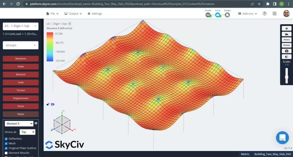
Afbeeldingen 15 en 16 bestaan uit het buigmoment in elke hoofdrichting. Het nemen van de momentverdeling en waarden, de software, SkyCiv, kan dan het totale staalversterkingsoppervlak verkrijgen.

Figuur 16. Eenrichtingsplaten in een klein bouwvoorbeeld. (Structurele 3D, SkyCiv Cloud-engineering).
Stalen versterkingsgebieden:
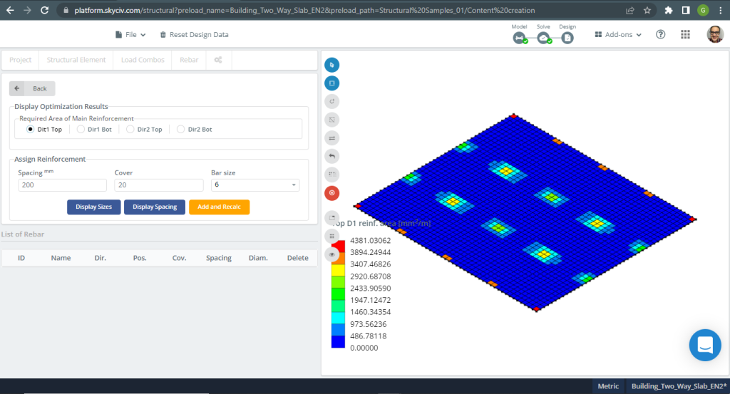
Figuur 17. Eenrichtingsplaten in een klein bouwvoorbeeld. (Structurele 3D, SkyCiv Cloud-engineering).
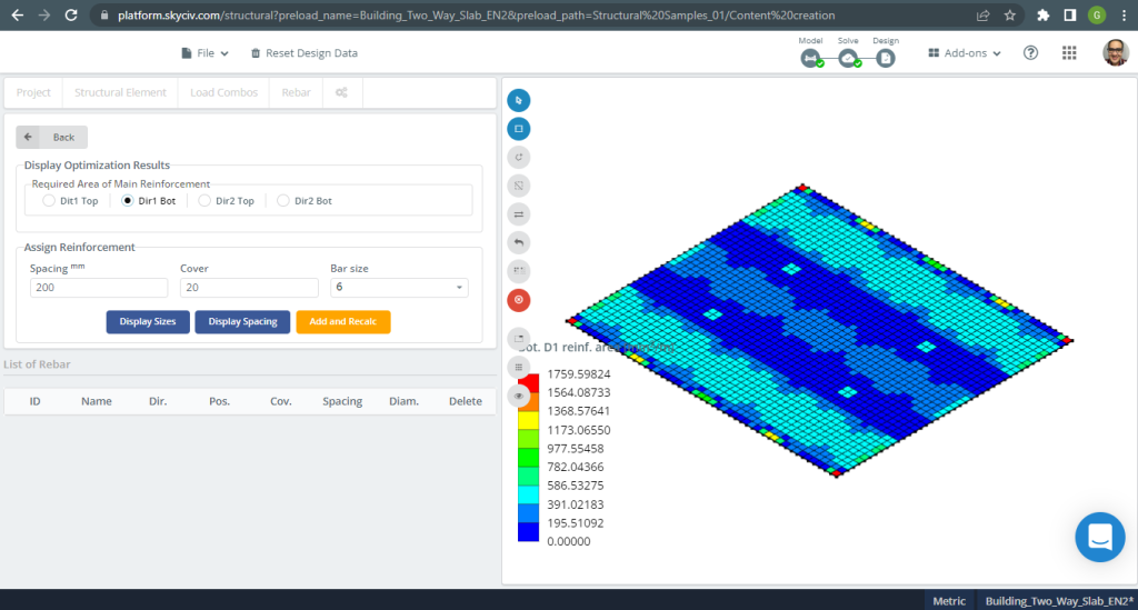
Figuur 18. Eenrichtingsplaten in een klein bouwvoorbeeld. (Structurele 3D, SkyCiv Cloud-engineering).
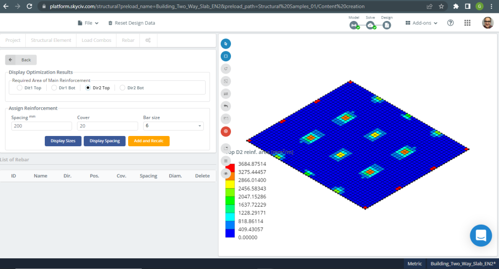
Figuur 19. Eenrichtingsplaten in een klein bouwvoorbeeld. (Structurele 3D, SkyCiv Cloud-engineering).
Figuur 20. Eenrichtingsplaten in een klein bouwvoorbeeld. (Structurele 3D, SkyCiv Cloud-engineering).
Vergelijking van resultaten
De laatste stap in dit voorbeeld van een tweerichtingsplaatontwerp is het vergelijken van het oppervlak van de stalen wapening verkregen door S3D-analyse en handmatige berekeningen.
Wapeningsstaal voor X-richting en kolomstrip
| Momenten en staalgebied | Exterieur Negatief Links | Exterieur Positief | Exterieur negatief recht | Binnenlands Negatief Links | Interieur Positief | Binnenlands negatief recht |
|---|---|---|---|---|---|---|
| \(EEN_{de opwaartse bodemdruk veroorzaakt bidirectionele buiging met trekspanningen aan het bodemoppervlak, HandCalcs} {mm^2}\) | 1498.366 | 1651.761 | 2247.55 | 2577.835 | 1651.761 | 1887.727 |
| \(EEN_{de opwaartse bodemdruk veroorzaakt bidirectionele buiging met trekspanningen aan het bodemoppervlak, S3D} {mm^2}\) | 3889.375 | 1040.00 | 4196.145 | 4196.145 | 520.00 | 3175.00 |
| \(\Delta_{verschil}\) (%) | 61.475 | 37.04 | 46.44 | 38.566 | 68.52 | 40.544 |
Als je nieuw bent bij SkyCiv, Meld u aan en test de software zelf!
Referenties
- B. Mosley, R. Hulse, J.H. Bungee , “Gewapend betonontwerp volgens Eurocode 2”, Zevende editie, Palgrave MacMillan.
- Bazan Enrique & Meli Piralla, “Seismisch ontwerp van constructies”, 1ed, DUIDELIJK.
- Eurocode 2: Ontwerp van betonconstructies.