Continue leden vs. Normale leden – wanneer u ze allemaal moet gebruiken
Invoering
In dit artikel wordt dieper ingegaan op de manier waarop leden lid zijn (of elementen) met elkaar verbinden via knooppunten en hoe dit wordt afgehandeld in de SkyCiv Solver. Knooppunten markeren een verbindingspunt tussen leden, zij zijn de scheiding van de stijfheidsmatrices.
Er kunnen verschillende soorten leden zijn. In feite, Structureel 3D heeft momenteel een totaal van 6 soorten leden. Een korte opmerking over vastgezette verbindingen, we zullen de twee soorten leden onderzoeken, aangezien dit fundamentele lidtypen zijn voor modellering in het algemeen. Er zijn twee hoofdelementtypen in Structural 3D: normale en continue leden. Deze discussie zal dieper ingaan op de manier waarop ze beide worden afgehandeld door de SkyCiv-oplosser, evenals de voordelen van het gebruik van de een van de ander.
Normale leden
Normale leden zijn elementen die ‘normaal’ worden behandeld’ in de zin dat de leden in de traditionele zin worden geanalyseerd.
Traditioneel, eindige elementenanalyse (LELIJK) oplossers werken met behulp van de directe stijfheidsmethode. Gebaseerd op de toegepaste belastingen en stijfheid van de elementen in de constructie, de verplaatsing van de constructie kan worden opgelost zoals weergegeven in de volgende vergelijking:
\(Q=KD\)
Waarbij:
\(Q=\) vector van stijfheid
\(K=\) globale stijfheidsmatrix (samengesteld uit de stijfheidsmatrix van elk lid)
\(D=\) vector van onbekende knoopverplaatsingen die onbekend zijn en opgelost moeten worden
SkyCiv Structurele 3D past deze formules toe op het model en verkrijgt de resultaten van elk knooppunt en lid.
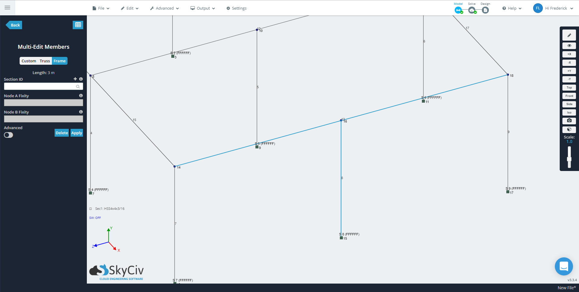
Doorlopende leden
Doorlopende leden in Structureel 3D zijn een type lid dat connectiviteit tussen twee knooppunten met een knooppunt mogelijk maakt(s) dat geen knoopverbinding met het lid heeft. Knooppuntverbindingen vinden plaats wanneer een knooppunt wordt toegewezen om twee of meer leden met elkaar te verbinden.
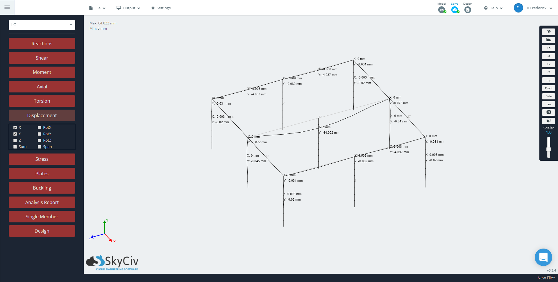
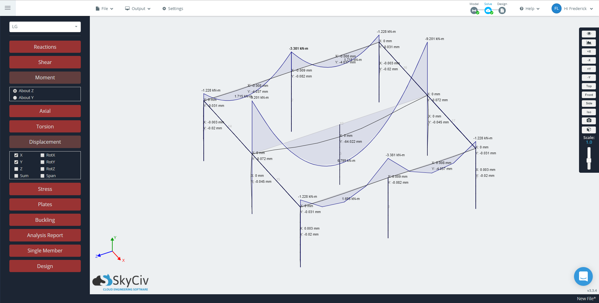
Het element dat in de onderstaande afbeelding het grootste afbuigt, wordt geselecteerd als ‘Normaal’’ lid, daarom herkent het de kolom over zijn lengte niet. Het lid wijzigen in ‘Continu’’ zullen “aansluiten” het lange lid van de kolom, wat het geval is voor de andere twee leden die een beperkte doorbuiging vertonen.
Voor- en nadelen van elk lidtype
Normale leden
Modellen die met normale leden zijn gebouwd, zijn waarschijnlijk compatibel met structurele analysesoftware van derden. Omdat andere programma's doorlopende leden mogelijk niet ondersteunen op de manier waarop Structural 3D dit implementeert, de verstrekte resultaten zijn mogelijk niet correct.
Het is belangrijk om te controleren of het model geen doorlopende leden bevat voordat u het exporteert.
In termen van analyse, omdat het lid is opgesplitst in eenvoudige leden, het aantal evaluatiepunten in het model is groter dan bij continue leden die hetzelfde aantal evaluatiepunten over twee of meer overspanningen dragen, waardoor de resultaten minder gedetailleerd zijn. U kunt het aantal evaluatiepunten verhogen in de Algemene Oplosserinstellingen, maar omdat dit de evaluatiepunten voor alle leden controleert, de analyse zou langer kunnen zijn. Dit kan een nadeel zijn bij het werken met grote en complexe constructies.
Doorlopende leden
Doorlopende leden, anderzijds, zijn erg handig als het gaat om het vergroten van de efficiëntie bij het modelleren. Doorlopende leden verminderen het aantal leden dat nodig is om een soortgelijk model te maken met normale leden. Dit heeft rechtstreeks invloed op de hoeveelheid belastingen die in uw project aanwezig zullen zijn. bijv., Het laden van een continu element met een verdeelde belasting versus het laden van elk normaal element met een verdeelde belasting.
Wat betreft analyse, Het verminderen van het aantal leden vermindert de rommel en maakt het gemakkelijker om de resultaten te interpreteren en te presenteren. Als u minder leden heeft, wordt het aantal volgende modelelementen in uw project kleiner, waardoor het gemakkelijker wordt om het gedrag van leden te zien. Bijvoorbeeld, met doorlopende leden, je kunt het gedrag over een groter bereik controleren, in plaats van een combinatie van normale leden over dezelfde periode.
Als het om ontwerp gaat, doorlopende elementen zijn ideaal voor balken van gewapend beton, omdat ze bedoeld zijn om zich monolithisch te gedragen. Omdat een overspanning gewoonlijk de doorsnede ertussen niet verandert, het is ook nuttig bij het identificeren van het vereiste staalprofiel voor een bepaalde overspanning. Bijvoorbeeld, doorlopende leden worden bijna altijd aanbevolen bij het ontwerpen van liggers of leden die daarin inlijsten, d.w.z., vloer- of dakframe.