In dit artikel, we zullen een plaatontwerpvoorbeeld ontwikkelen met behulp van de laatste versie van ACI-318-19: “Bouwvereisten voor constructief beton,” bestaande uit de modellering in SkyCiv van een laagbouwgebouw van gewapend beton, gericht op de vergelijking van softwareresultaten en handmatige berekeningen volgens een door ACI geaccepteerde methode: “De directe ontwerpmethode voor platen.” Deze procedure bestaat uit het toewijzen van het totale moment aan verschillende stroken langs de hoofdrichtingen en raamwerken van het gebouw door middel van handige factoren om de hoeveelheid wapening en de locatie in de plaat te bepalen..
We hopen dat je het vorige artikel hebt gelezen, Plaatontwerp in S3D, om jezelf voor te stellen aan het modelleren en ontwerpen van platen met SkyCiv. Een ander nuttig stukje informatie dat u kunt overwegen, vindt u in Hoe platen te modelleren? Zodra u beide documenten heeft gelezen, voel je vrij om in het volgende volledig bewerkte plaatvergelijkingsvoorbeeld te duiken!
Algemene gebouwindeling
De volgende afbeeldingen tonen een isometrisch aanzicht en vlakafmetingen van het te berekenen voorbeeld. Het gebouw heeft twee verhoogde vlakke platen zonder balken tussen kolomsteunen.
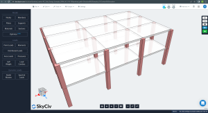
Figuur 1. Isometrische weergave van het voorbeeld van een gebouw
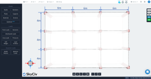
Figuur 2. Afmetingen plaat
Directe ontwerpmethode voor tweerichtingsplaten (DDM)
Beperkingen
ACI 318 maakt het gebruik van de DDM mogelijk om platen van gewapend beton te ontwerpen voor zwaartekrachtbelastingen, die een aantal benodigdheden verzamelen volgens de geometrie, belastingsrelaties, symmetrie, enzovoort. We kunnen deze beperkingen in de volgende lijst samenvatten (PCA-notities):
- “Er moeten drie of meer ononderbroken overspanningen in elke richting zijn.”: Figuur 2 toont drie overspanningen in elke hoofdrichting, longitudinaal en transversaal. OK!
- “Plaatpanelen moeten rechthoekig zijn met een verhouding van langere tot kortere overspanning (hartlijn-naar-hartlijn van steunen) niet groter dan 2.”: Volgens figuur 2, de verhouding is gelijk aan \({\frac{l_1}{4}= frac{6m}{4m}=1,5 < 2}\). OK!
- “Opeenvolgende overspanningen (hartlijn-naar-hartlijn van steunen) in elke richting mag niet meer dan . verschillen 1/3 van de langere spanwijdte”. De overspanningslengtes zijn in elke richting hetzelfde, 6m tot longitudinaal en 4 m tot transversaal. OK!
- “Kolommen mogen niet meer dan . worden verschoven 10% van de overspanning (in de richting van offset) van beide assen tussen hartlijnen van opeenvolgende kolommen”. Het gebouwvoorbeeld heeft geen verschuivingen in kolommen. OK!
- “Belastingen moeten gelijkmatig worden verdeeld, met de niet-factored of service live load niet meer dan twee keer de niet-factored of service dead load (L/D 2)”. Neem de waarden van elke zwaartekrachtbelasting, de verhouding wordt gedefinieerd als \({\frac{L}{D}= frac{2}{7.8}=0,256 < 2}\). OK!.
- “Voor in twee richtingen ondersteunde platen, relatieve stijfheid van liggers in twee loodrechte richtingen moet voldoen aan de minimum- en maximumvereisten die in de code worden vermeld.” Al tevreden; er zitten geen balken in de platen. OK!
- “Herverdeling van negatieve momenten per code is niet toegestaan.” Vanwege de eenvoud van het voorbeeld, het zal niet nodig zijn om negatieve momenten in de platen opnieuw te verdelen. OK!.
Definitie van longitudinale en transversale stroken
De plaat in DDM moet worden verdeeld in twee hoofdstroken voor de analyse en het ontwerp van een bepaald lijnraster: kolom en middelste stroken. De breedte voor kolomstroken is de kleinste van \({\frac {l_1}{4}}\) en \({\frac{l_2}{4}}\), waar \({l_1}\) is de lengte van de overspanning langs het lijnraster en \({l_2}\) is de dwarslengte loodrecht.
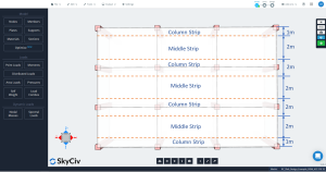
Figuur 3. Lengtekolom en middenstroken.
![]()
Figuur 4. Dwarskolom en middenstroken.
Minimale dikte
ACI-318 stelt voor om de vergelijking te gebruiken: \({t_{min}}= {\frac{l_n}{30}}={\frac{6m-0.50m}{30}}=0,1833m = 0,20m)
Voorafgaande controle van de schuifsterkte
Voordat u de stalen wapeningswapening berekent, Het wordt aanbevolen om het afschuifvermogen van de plaat te controleren, één voor directe afschuiving in de verbinding en één voor de ponsafschuifcapaciteit op de verbindingsplaatkolom.
Om de afschuifvraag te berekenen, wij hanteren de volgende zwaartekrachtbelastingen:
- Eigengewicht plaat: \({ZW={\gamma_c}\keer {t_{plaat}}={24 {\frac{kN}{m^3}}}\keer {0.20m}=4,8{\frac{kN}{m^2}} }\)
- Bovenliggende dode belasting: \({SD={3 {\frac{kN}{m^2}}}}\)
- Totale dode last (SW+SD): \({D={7.8 {\frac{kN}{m^2}}}}\)
- Live laden (Residentiële bezetting) : \({L={2 {\frac{kN}{m^2}}}}\)
- Gefactoriseerde sterktebelasting (1.2D+1,6L): \({q_{u}={12.56 {\frac{kN}{m^2}}}}\)
De eerste afschuifcontrole is de “balk-afschuiving” type, waarbij de volgende afbeelding het gebied aangeeft dat in aanmerking moet worden genomen om de totale afschuiving te verkrijgen. We inspecteren elke richting, het grotere gebied innemen.
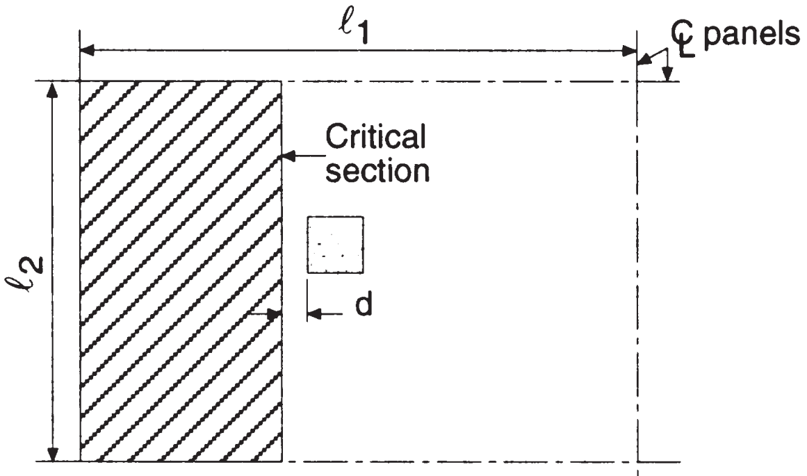
Figuur 5. Balkafschuiving aan de binnenkolom (Nadim Hassoun en Akthem AI-manager, “Structurele betontheorie en ontwerp”)
Waarbij:
- Lengte overspanning in lengterichting, \({l_1 = 6,0 m }\)
- Lengte overspanning in dwarsrichting, \({l_2 = 4,0 m}\)
- Totaal zijriviergebied, afschuiving in lengterichting \({A_t = l_2 tijden (\frac{l_1}{2}-\frac{c_1}{2}-d) = 4,0 m maal (\frac{6.0m}{2}-\frac{0.50m}{2}-0.17m) = 10.32 m^2}\) (geselecteerd)
- Totaal zijriviergebied, afschuiving in dwarsrichting, \({A_t = l_1 tijden (\frac{l_2}{2}-\frac{c_2}{2}-d) = 6,0 m maal (\frac{4.0m}{2}-\frac{0.50m}{2}-0.17m) = 9.48 m^2}\)
- Afmeting vierkante kolommen, \({c_1 = c_2 = 0,50 m}\)
- Afstand D, \({d = h_{plaat} – dekking = 0,20m – 0.03m = 0,17 m }\)
Daarom, de maximale liggerafschuiving in de binnenste kolom is
\({V_u =q_umaal A_t =12,56 {\frac{kN}{m^2}}\keer 10.32 m^2 = 129.62 kN }\)
Dit wordt vergeleken met de schuifweerstand, \({\phi_sV_c}\)
- Betonsterkte, \({f’_c = 25 MPa}\)
- Opbrengst wapeningsstaal sterkte, \({f_y = 420 MPa}\)
- \({\phi_s = 0.75}\)
- \({\phi_sV_c = 0,17phi_slambdasqrt(f'_c) b_w d; b_w=l_2}\)
\({\phi_sV_c = 0,17maal 0,75maal 1maal sqrt(25 MPa) \keer 4000 mmtijden 170 mm= 433.50 kN }\)
We kunnen zien dat de schuifweerstand groter is dan de schuifbehoefte: \({\phi_sV_c = 433.50 kN > V_u = 129.62 kN }\) OK!.
Volgens de volgende afbeeldingen, we moeten de ponsafschuifcapaciteit en de kracht berekenen die het beton moet weerstaan in de interne plaat-kolomverbinding. De bedoeling van de code bij het controleren van de ponsafschuiving is het handhaven van lage schuifspanningswaarden.
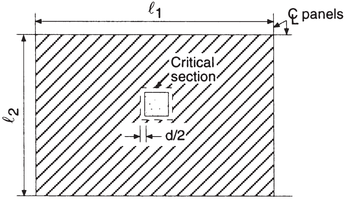
Figuur 6. Tweezijdige afschuiving aan de binnenkolom (Nadim Hassoun en Akthem AI-manager, “Structurele betontheorie en ontwerp”)
- Totaal zijriviergebied, ponsschaar, \({A_t = l_1 maal l_2 – (c_1+d)^2 = 6,0 m maal 4,0 m – (0.50m+0,17m)➔⡔ Koop generieke tadalafil 23.55 m^2}\) (hetzelfde gebied voor beide hoofdrichtingen)
De totale te weerstaan dwarskracht bedraagt
\({V_u =q_umaal A_t =12,56 {\frac{kN}{m^2}}\keer 23.55 m^2 = 295.79 kN }\)
Om de ponsafschuifcapaciteit in een tweerichtingsplaat te verkrijgen, we zullen de empirische methode gebruiken die is vastgelegd in code ACI-318, waarbij rekening wordt gehouden met de maximale schuifspanning die beschikbaar is in de effectieve omtrek van de kritische sectie. De meer conservatieve uitdrukking voor de binnenkolom is
- Ponscapaciteit, \({\phi_sV_c = 0,33phi_slambdasqrt(f'_c) b_0 d; b_0=4keer (c_1+d)}\)
Daarom, we hebben de schuifweerstand van
\({\phi_sV_c = 0,33keer 0.75 \keer 1 \sqrt(25 MPa) \keer (4\keer (500 mm+170 mm)\keer 170 mm) = 563.81 kN }\)
We kunnen zien dat de schuifweerstand groter is dan de schuifbehoefte: \({\phi_sV_c = 563.81 kN > V_u = 295.75 kN }\) OK!.
We hebben de eisen inzake afschuiving in één en twee richtingen bij de interne kolomverbinding geverifieerd. Omdat beide eisen minder zijn dan hun respectievelijke capaciteiten of weerstanden, we gaan nu verder met het berekenen van de hoofdwapening voor het buigen van de plaat.
Als je nieuw bent bij SkyCiv, Meld u aan en test de software zelf!
Totaal meegerekend statisch moment per overspanning.
Het maximale moment dat kan worden ontwikkeld tot een dubbele ligger met vast uiteinde is een isostatisch moment gelijk aan \({M = frac{wtijden {l_1}^ 2}{8}}\) (Zie figuur 6).
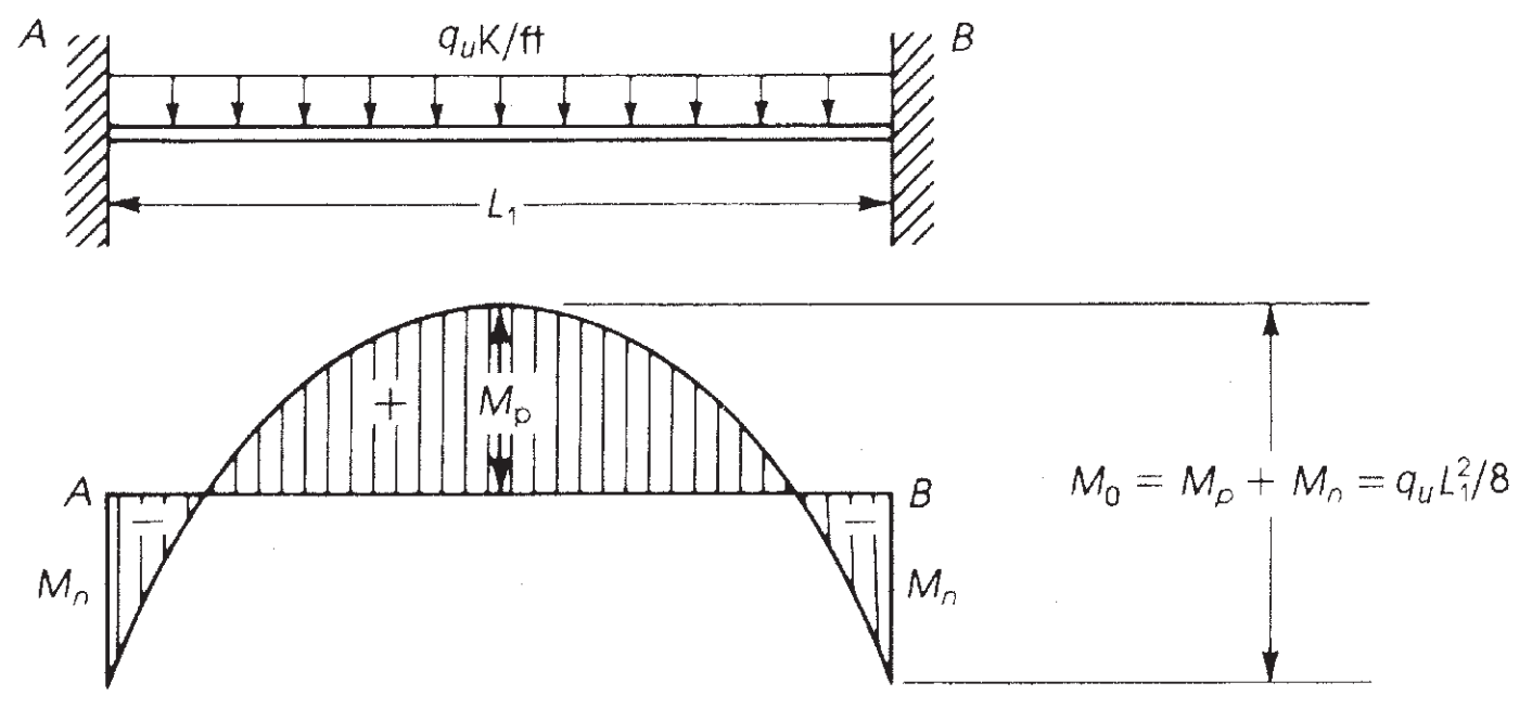
Figuur 7. Buigmoment in een ligger met een vast uiteinde. (Nadim Hassoun en Akthem AI-manager, “Structurele betontheorie en ontwerp”)
ACI-18 neemt dit principe over en, voor de directe ontwerpmethode (DDM), stelt het maximale statische moment vast waarmee per overspanning rekening moet worden gehouden \({M_0}\)
Lengterichting:
- \({M_0 = frac {q_utijden l_2tijden {l_{n,1}}^ 2}{8}}\)
- \({M_0 = frac {12.56 {\frac{kN}{m^2}}\maal 4,0mkeer (6m-0.50m)^ 2}{8}=189,97 kN-m}\)
Omgekeerde richting:
- \({M_0 = frac {q_utijden l_1tijden {l_{n,2}}^ 2}{8}}\)
- \({M_0 = frac {12.56 {\frac{kN}{m^2}}\maal 6,0mkeer (4m-0.50m)^ 2}{8}=115,40 kN-m}\)
De volgende stap is het toekennen van dit totale moment, rekening houdend met het paneeltype, interieur of exterieur. (Zie figuur 7). Daarna, omdat de overspanningen continu zijn, het is noodzakelijk om het moment ook in positief en negatief te verdelen. Dit laatste wordt weergegeven in afbeeldingen 8 en 9.
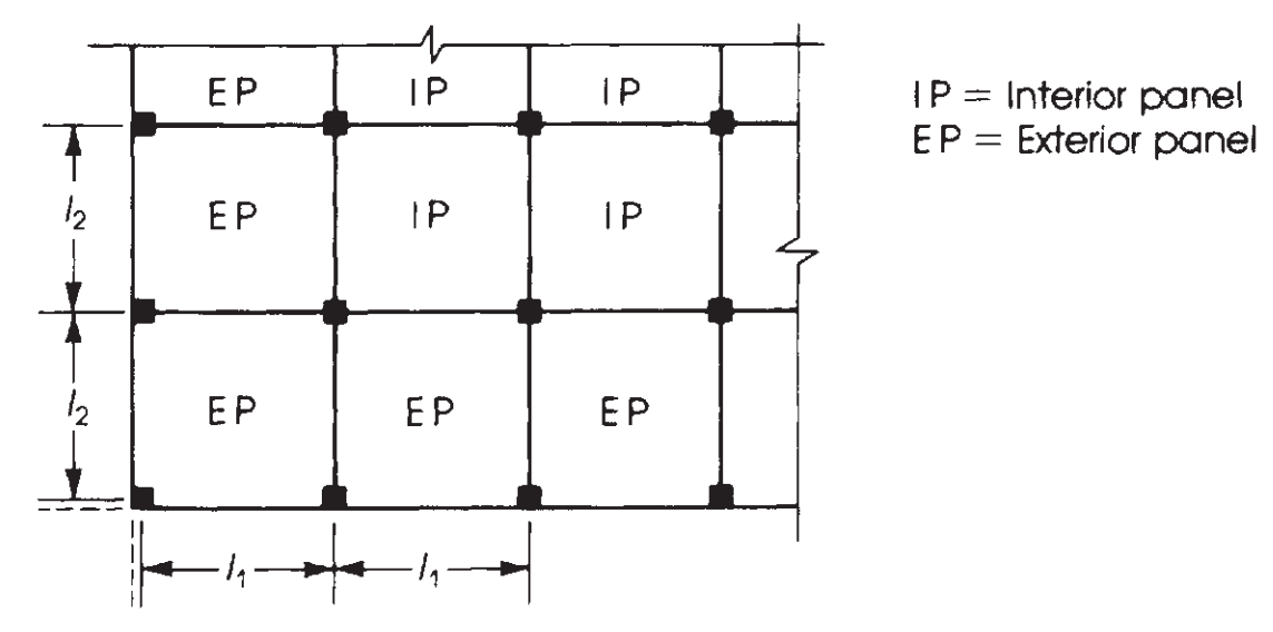
Figuur 8. Definitie van panelen op basis van hun relatieve positie in een plaatplan. (Nadim Hassoun en Akthem AI-manager, “Structurele betontheorie en ontwerp”)
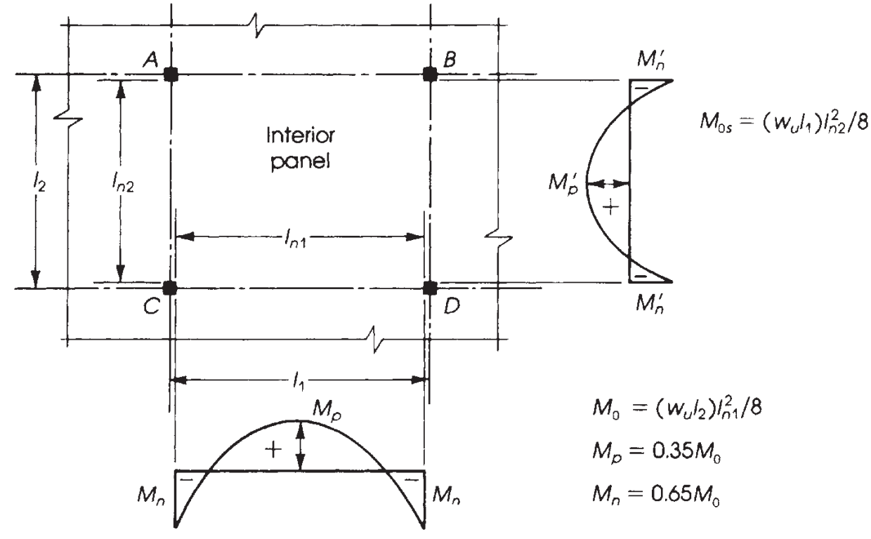
Figuur 9. Verdeling van momenten in een binnenpaneel. (Nadim Hassoun en Akthem AI-manager, “Structurele betontheorie en ontwerp”)
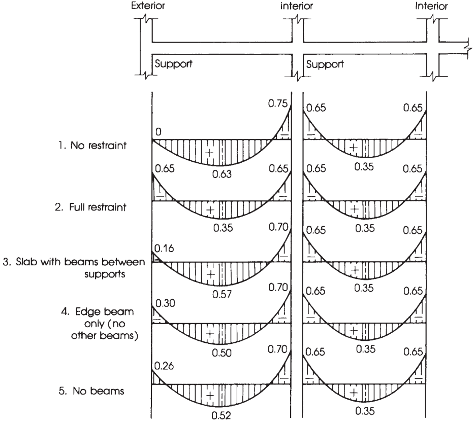
Het is cruciaal om de juiste verdeling van momenten te kennen, afhankelijk van de plaat die we ontwerpen. In dit voorbeeld, we hebben het laatste geval in de volgende afbeelding (figuur 9), “Geen balken,” toegepast op een vlakke plaat of massieve plaat zonder balk, noch op de rand, noch tussen steunen.
Het belangrijkste verschil in de vijf gevallen weergegeven in figuur 9 is de momentfracties die moeten worden toegewezen aan buitenpanelen, waarin de relatieve terughoudendheid aan het einde de te berekenen waarden verandert.
Figuur 10. Verdeling van het totale statische moment in negatieve en positieve spanmomenten. (Nadim Hassoun en Akthem AI-manager, “Structurele betontheorie en ontwerp”)
Verdeling van het totale factormoment \({M_0}\) per span in negatieve en positieve momenten.
Eenmaal \({M_0}\) is berekend, het is tijd om de fractie van momenten in elke ontwerpstrook in positief en negatief in te delen, dat is, kolom en middelste stroken. Voor meer duidelijkheid, figuur 10 helpt bij het specificeren van de juiste factor waarmee rekening moet worden gehouden bij de verdeling van het totale moment.
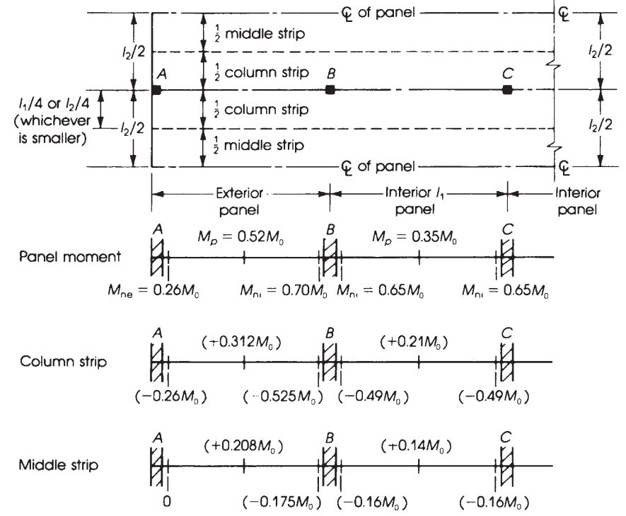
Figuur 11. Breedte van het equivalente stijve frame en verdeling van momenten in vlakke platen. (Nadim Hassoun en Akthem AI-manager, “Structurele betontheorie en ontwerp”)
Gebruikmakend van de voorgaande factoren aangegeven in de figuur 10, we verkrijgen in de volgende tabel het ultieme moment.
Lengterichting: \({M_0 = 189.97 kN-m}\)
| Span (ES:Buitenkant, IS:Interieur) | Totaal moment (kN-m) | Kolomstrookmoment (kN-m) | Middenstrookmoment (kN-m) |
|---|---|---|---|
| Exterieur negatieve ES | 0.26M0=49.39 | 0.26M0=49.39 | 0 |
| Positieve ES | 0.52M0=98.78 | 0.31M0=58.89 | 0.21M0=39.89 |
| Interieur negatieve ES | 0.70M0=132.98 | 0.53M0=100.68 | 0.17M0=32.29 |
| Positieve IS | 0.35M0=66.49 | 0.21M0=39.89 | 0.14M0=26.60 |
| Negatieve IS | 0.65M0=123.48 | 0.49M0=93.09 | 0.16M0=30.40 |
Met het moment eenmaal verdeeld, Het is tijd om te bepalen welke stalen wapening in de plaat moet worden geplaatst. We ontwikkelen slechts één berekening en vervolgens alle resultaten in een tabel.
Moment in de externe negatieve overspanning in de kolomstrook, \({M_u = 49.39 kN-m}\)
- Veronderstelde spanning gecontroleerde sectie. \({\phi_f = 0.9}\)
- Breedte van de kolomstrook, \({b=2,0m}\)
- Stalen versterkingsgebied, \({A_s = frac{M_u}{\phi_ftimes 0.9dtimes fy}= frac{49.39kN-m}{0.9\keer 0.9(0.17m)\keer 420 MPa}=853,996 {mm}^ 2}\)
- \({\de opwaartse bodemdruk veroorzaakt bidirectionele buiging met trekspanningen aan het bodemoppervlak{min} = 0.0018}\). Stalen minimale wapeningsoppervlakte, \({EEN_{s,min}=rho_{min}\maal bmaal d = 0.0018 \maal 2,0 m maal 0,17 m =612 {mm}^ 2}\). Nu, controleer of de sectie zich gedraagt als spanningsgestuurd.
- \({a = frac{A_stimes f_y}{0.85\maal f'cmaal b} = frac{853.996 {mm}^2keer 420 MPa}{0.85\keer 25 MPamaal 2,0 m }= 8.439 mm}\)
- \({c = frac{een}{\bèta_1}= frac{8.439 mm}{0.85} = 9,929 mm }\)
- \({\varepsilon_t = (\frac{0.003}{c})\keer d – 0.003 = (\frac{0.003}{9.929mm})\keer 170 mm – 0.003 = 0.048 > 0.005 }\) OK!, het is een door spanning gecontroleerd gedeelte!.
| Span(ES:Buitenkant, IS:Interieur) | Kolomstrookmoment (kN-m) | \({EEN_{s,berekening} ({mm}^ 2)}\) | \({EEN_{s,min} ({mm}^ 2)}\) | \({een (mm)}\) | \({c (mm)}\) | \({\varepsilon_t > 0.005}\) |
|---|---|---|---|---|---|---|
| Exterieur negatieve ES | 49.39 | 853.996 | 612.0 | 8.439 | 9.929 | 0.048 > 0.005! |
| Positieve ES | 58.89 | 1018.259 | 612.0 | 10.063 | 11.839 | 0.040 > 0.005! |
| Interieur negatieve ES | 100.68 | 1740.844 | 612.0 | 17.204 | 20.24 | 0.022 > 0.005! |
| Positieve IS | 39.89 | 689.733 | 612.0 | 6.816 | 8.019 | 0.06 > 0.005! |
| Negatieve IS | 93.09 | 1609.607 | 612.0 | 15.907 | 18.714 | 0.024 > 0.005! |
Moment in de buitenste positieve overspanning in de middenstrook, \({M_u = 39.89 kN-m}\)
- Veronderstelde spanning gecontroleerde sectie. \({\phi_f = 0.9}\)
- Breedte middenstrook, \({b=2,0m}\)
- Stalen versterkingsgebied, \({A_s = frac{M_u}{\phi_ftimes 0.9dtimes fy}= frac{39.89kN-m}{0.9\keer 0.9(0.17m)\keer 420 MPa}=689,733 {mm}^ 2}\)
- \({\de opwaartse bodemdruk veroorzaakt bidirectionele buiging met trekspanningen aan het bodemoppervlak{min} = 0.0018}\). Stalen minimale wapeningsoppervlakte, \({EEN_{s,min}=rho_{min}\maal bmaal d = 0.0018 \maal 2,0 m maal 0,17 m =612 {mm}^ 2}\). Nu, controleer of de sectie zich gedraagt als spanningsgestuurd.
- \({a = frac{A_stimes f_y}{0.85\maal f'cmaal b} = frac{689.766 {mm}^2keer 420 MPa}{0.85\keer 25 MPamaal 2,0 m }= 6.816 mm}\)
- \({c = frac{een}{\bèta_1}= frac{6.816 mm}{0.85} = 8.019 mm }\)
- \({\varepsilon_t = (\frac{0.003}{c})\keer d – 0.003 = (\frac{0.003}{8.019mm})\keer 170 mm – 0.003 = 0.0605 > 0.005 }\) OK!, het is een door spanning gecontroleerd gedeelte!.
| Span(ES:Buitenkant, IS:Interieur) | Middenstrookmoment (kN-m) | \({EEN_{s,berekening} ({mm}^ 2)}\) | \({EEN_{s,min} ({mm}^ 2)}\) | \({een (mm)}\) | \({c (mm)}\) | \({\varepsilon_t > 0.005}\) |
|---|---|---|---|---|---|---|
| Exterieur negatieve ES | 0 | 0.00 | 612.0 | 6.048 | 7.115 | 0.069 > 0.005! |
| Positieve ES | 39.89 | 689.733 | 612.0 | 6.816 | 8.019 | 0.061 > 0.005! |
| Interieur negatieve ES | 32.29 | 558.322 | 612.0 | 6.048 | 7.115 | 0.069 > 0.005! |
| Positieve IS | 26.60 | 459.937 | 612.0 | 6.048 | 7.115 | 0.069 > 0.005! |
| Negatieve IS | 30.40 | 525.642 | 612.0 | 6.048 | 7.115 | 0.069 > 0.005! |
Omgekeerde richting: \({M_0 = 115.40 kN-m}\)
| Span (ES:Buitenkant, IS:Interieur) | Totaal moment (kN-m) | Kolomstrookmoment (kN-m) | Middenstrookmoment (kN-m) |
|---|---|---|---|
| Exterieur negatieve ES | 0.26M0=30.00 | 0.26M0=30.00 | 0 |
| Positieve ES | 0.52M0=60.00 | 0.31M0=35.77 | 0.21M0=24.23 |
| Interieur negatieve ES | 0.70M0=80.78 | 0.53M0=61.16 | 0.17M0=19.62 |
| Positieve IS | 0.35M0=40.39 | 0.21M0=24.23 | 0.14M0=16.16 |
| Negatieve IS | 0.65M0=75.01 | 0.49M0=56.55 | 0.16M0=18.46 |
Met het moment eenmaal verdeeld, het is tijd om te bepalen welke stalen wapeningswapening in de plaat moet worden geplaatst. We ontwikkelen slechts één berekening en vervolgens alle resultaten in een tabel.
Moment in de externe negatieve overspanning in de kolomstrook, \({M_u = 30.00 kN-m}\)
- Veronderstelde spanning gecontroleerde sectie. \({\phi_f = 0.9}\)
- Breedte van de kolomstrook, \({b=2,0m}\)
- Stalen versterkingsgebied, \({A_s = frac{M_u}{\phi_ftimes 0.9dtimes fy}= frac{30.00kN-m}{0.9\keer 0.9(0.17m)\keer 420 MPa}=518,726 {mm}^ 2}\)
- \({\de opwaartse bodemdruk veroorzaakt bidirectionele buiging met trekspanningen aan het bodemoppervlak{min} = 0.0018}\). Stalen minimale wapeningsoppervlakte, \({EEN_{s,min}=rho_{min}\maal bmaal d = 0.0018 \maal 2,0 m maal 0,17 m =612 {mm}^ 2}\). Nu, controleer of de sectie zich gedraagt als spanningsgestuurd.
- \({a = frac{A_stimes f_y}{0.85\maal f'cmaal b} = frac{518.726 {mm}^2keer 420 MPa}{0.85\keer 25 MPamaal 2,0 m }= 6.048 mm}\)
- \({c = frac{een}{\bèta_1}= frac{6.048 mm}{0.85} = 7,115 mm }\)
- \({\varepsilon_t = (\frac{0.003}{c})\keer d – 0.003 = (\frac{0.003}{7.115mm})\keer 170 mm – 0.003 = 0.069 > 0.005 }\) OK!, het is een door spanning gecontroleerd gedeelte!.
| Span(ES:Buitenkant, IS:Interieur) | Kolomstrookmoment (kN-m) | \({EEN_{s,berekening} ({mm}^ 2)}\) | \({EEN_{s,min} ({mm}^ 2)}\) | \({een (mm)}\) | \({c (mm)}\) | \({\varepsilon_t > 0.005}\) |
|---|---|---|---|---|---|---|
| Exterieur negatieve ES | 30.00 | 518.726 | 612.0 | 6.048 | 7.115 | 0.069 > 0.005! |
| Positieve ES | 35.77 | 618.494 | 612.0 | 6.112 | 7.191 | 0.068 > 0.005! |
| Interieur negatieve ES | 61.16 | 1057.509 | 612.0 | 10.451 | 12.295 | 0.038 > 0.005! |
| Positieve IS | 24.23 | 418.958 | 612.0 | 6.048 | 7.115 | 0.069 > 0.005! |
| Negatieve IS | 56.55 | 977.799 | 612.0 | 9.663 | 11.368 | 0.042 > 0.005! |
Moment in de buitenste positieve overspanning in de middenstrook, \({M_u = 24.23 kN-m}\)
- Veronderstelde spanning gecontroleerde sectie. \({\phi_f = 0.9}\)
- Breedte van de kolomstrook, \({b=4,0m}\)
- Stalen versterkingsgebied, \({A_s = frac{M_u}{\phi_ftimes 0.9dtimes fy}= frac{24.23 kN-m}{0.9\keer 0.9(0.17m)\keer 420 MPa}=418,958 {mm}^ 2}\)
- \({\de opwaartse bodemdruk veroorzaakt bidirectionele buiging met trekspanningen aan het bodemoppervlak{min} = 0.0018}\). Stalen minimale wapeningsoppervlakte, \({EEN_{s,min}=rho_{min}\maal bmaal d = 0.0018 \maal 4,0 m maal 0,17 m =1224 {mm}^ 2}\). Nu, controleer of de sectie zich gedraagt als spanningsgestuurd.
- \({a = frac{A_stimes f_y}{0.85\maal f'cmaal b} = frac{1224 {mm}^2keer 420 MPa}{0.85\keer 25 MPamaal 4,0 m }= 6.048 mm}\)
- \({c = frac{een}{\bèta_1}= frac{6.048 mm}{0.85} = 7.115 mm }\)
- \({\varepsilon_t = (\frac{0.003}{c})\keer d – 0.003 = (\frac{0.003}{7.115mm})\keer 170 mm – 0.003 = 0.069 > 0.005 }\) OK!, het is een door spanning gecontroleerd gedeelte!.
| Span(ES:Buitenkant, IS:Interieur) | Middenstrookmoment (kN-m) | \({EEN_{s,berekening} ({mm}^ 2)}\) | \({EEN_{s,min} ({mm}^ 2)}\) | \({een (mm)}\) | \({c (mm)}\) | \({\varepsilon_t > 0.005}\) |
|---|---|---|---|---|---|---|
| Exterieur negatieve ES | 0.00 | 0.00 | 1224.00 | 6.048 | 7.115 | 0.069 > 0.005! |
| Positieve ES | 24.23 | 418.958 | 1224.00 | 6.048 | 7.115 | 0.069 > 0.005! |
| Interieur negatieve ES | 19.62 | 339.247 | 1224.00 | 6.048 | 7.115 | 0.069 > 0.005! |
| Positieve IS | 16.16 | 279.420 | 1224.00 | 6.048 | 7.115 | 0.069 > 0.005! |
| Negatieve IS | 18.46 | 319.189 | 1224.00 | 6.048 | 7.115 | 0.069 > 0.005! |
Als je nieuw bent bij SkyCiv, Meld u aan en test de software zelf!
SkyCiv S3D-ontwerpmodule
In deze sectie, we beschrijven het ontwerpresultaat met behulp van de module voor plaatontwerp in SkyCiv. We leggen niet uit hoe je de structuur moet modelleren en analyseren (voor deze, zie gerelateerde artikelen over dit onderwerp in onze documentatie: Hoe een structuur te modelleren in SkyCiv?, Hoe belastingen toe te passen in mijn gebouwmodel? en Hoe u een lineair-elastische analyse uitvoert?)
Het is handig om een fijn gaas op de platen aan te brengen om een nauwkeurig ontwerpresultaat te verkrijgen. Bekijk de volgende afbeelding voor meer duidelijkheid.
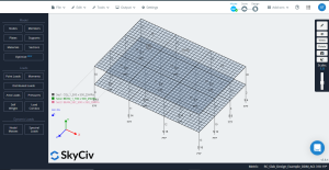
Figuur 12. Fijner gaas toegepast op platen
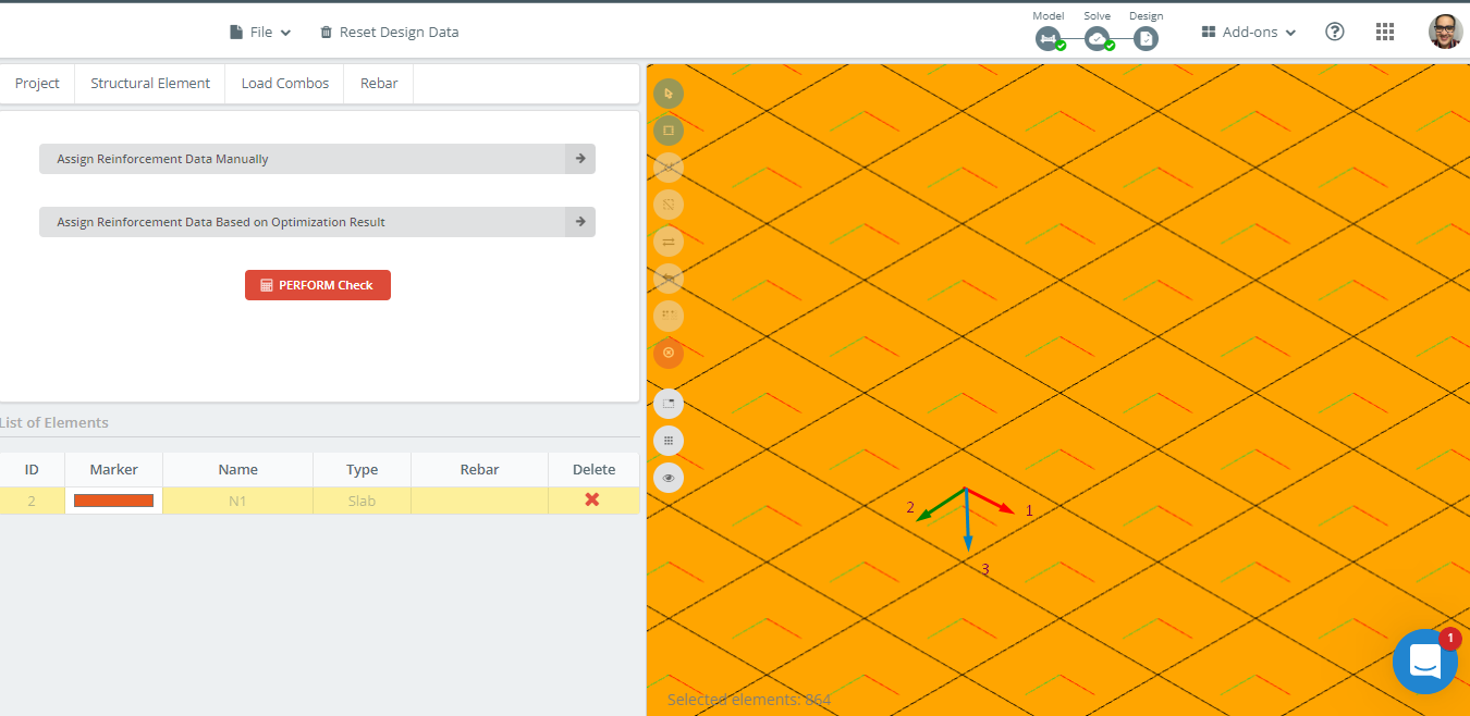
De volgende stap is het uitvoeren van de ontwerpmodule en het selecteren van de opties die een geoptimaliseerd gebied voor stalen wapening berekenen.
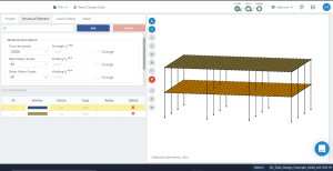
Figuur 13. Definitie van plaatbetoneigenschappen vóór ontwerpoptimalisatie.
Figuur 14 vertegenwoordigt de oriëntatie van de lokale assen van de plaat. Omdat lokale as 3 is naar beneden, de “top” is de bodem, als de “bodem” zal de top zijn, waardoor de gegevens correct uit het ontwerp worden overgenomen.
Een ander belangrijk feit is de maaswijdte van de plaat; het is een vierkant plaatelement met planafmetingen van 500 mm x 500 mm. SkyCiv S3D geeft het wapeningsoppervlak als een geïntegreerde waarde per eindig element. Dus, als we het totale wapeningsoppervlak van een kolom of middenstrook willen verkrijgen, we moeten de gemiddelde waarde berekenen op basis van het aantal elementen dat de te analyseren stripbreedte optelt. Bijvoorbeeld, voor de kolomstrook, vier elementen zullen worden overwogen (4×0.5m = 2 m).
Figuur 14. Oriëntatie van lokale assen in plaatvoorbeeld.
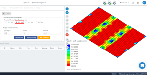
Eerste, we analyseren het benodigde wapeningsgebied in de lengterichting in de as 1.
Kolomstrook
- Extern negatief moment (bovenste versteviging): \({EEN_{s,top} =(119.09\keer 2 + 952.72 + 833.64 )\frac{{mm}^ 2}{m} \maal 0,50m= 1012.27 {mm}^ 2}\)
- Exterieur positief moment (onderste versteviging): \({EEN_{s,bot} = 4*463.90 \frac{{mm}^ 2}{m}\maal 0,50m= 927.80 {mm}^ 2}\)
- Exterieur interieur negatief moment (bovenste versteviging): \({EEN_{s,top} =(1071.82\keer 2 +714.54 \keer 2 )\frac{{mm}^ 2}{m} \maal 0,50m= 1786.36 {mm}^ 2}\)
- Interieur positief moment(onderste versteviging): \({EEN_{s,bot} = 4*309.27 \frac{{mm}^ 2}{m}\maal 0,50m= 618.54 {mm}^ 2}\)
- Innerlijk negatief moment (bovenste versteviging): \({EEN_{s,top} =(714.54\keer 2 +952.73 \keer 2 )\frac{{mm}^ 2}{m} \maal 0,50m= 1667.27 {mm}^ 2}\)
Middelste strook
- Extern negatief moment (bovenste versteviging): \({EEN_{s,top} =(119.09\keer 4)\frac{{mm}^ 2}{m} \maal 0,50m= 238.18 {mm}^ 2}\)
- Exterieur positief moment (onderste versteviging): \({EEN_{s,bot} = (463.90\keer 2 +412.36 \keer 2 ) \frac{{mm}^ 2}{m}\maal 0,50m= 876.26 {mm}^ 2}\)
- Exterieur interieur negatief moment (bovenste versteviging): \({EEN_{s,top} =(357.27\keer 2 +476.36 \keer 2 )\frac{{mm}^ 2}{m} \maal 0,50m= 833.63 {mm}^ 2}\)
- Interieur positief moment(onderste versteviging): \({EEN_{s,bot} = 4*257.72 \frac{{mm}^ 2}{m}\maal 0,50m= 515.44 {mm}^ 2}\)
- Innerlijk negatief moment (bovenste versteviging): \({EEN_{s,top} =(357.27\keer 2 +476.36 \keer 2 )\frac{{mm}^ 2}{m} \maal 0,50m= 833.63 {mm}^ 2}\)

Figuur 15. Optimalisatie resulteert in richting “1” en de bovenzijde (Onderkant, Eigenlijk).
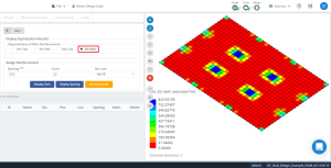
Figuur 16. Optimalisatie resulteert in richting “1” en de onderkant (Bovenkant, Eigenlijk).
Uiteindelijk, we analyseren het vereiste wapeningsgebied langs de dwarsrichting in de as 2.
Kolomstrook
- Extern negatief moment (bovenste versteviging): \({EEN_{s,top} =(91.55\keer 2 + 457.73 + 549.28 )\frac{{mm}^ 2}{m} \maal 0,50m= 595.055 {mm}^ 2}\)
- Exterieur positief moment (onderste versteviging): \({EEN_{s,bot} = (269.68\keer 3+239.72) \frac{{mm}^ 2}{m}\maal 0,50m= 524.38 {mm}^ 2}\)
- Exterieur interieur negatief moment (bovenste versteviging): \({EEN_{s,top} =(823.92\keer 2 +549.28 +457.73)\frac{{mm}^ 2}{m} \maal 0,50m= 1327.43 {mm}^ 2}\)
- Interieur positief moment(onderste versteviging): \({EEN_{s,bot} = (179.79\keer 3+149.82) \frac{{mm}^ 2}{m}\maal 0,50m= 344.60 {mm}^ 2}\)
- Innerlijk negatief moment (bovenste versteviging): \({EEN_{s,top} =(823.92\keer 2 +549.28 +457.73)\frac{{mm}^ 2}{m} \maal 0,50m= 1327.43 {mm}^ 2}\)
Middelste strook
- Extern negatief moment (bovenste versteviging): \({EEN_{s,top} =(183.09\maal 2+91,55maal 6)\frac{{mm}^ 2}{m} \maal 0,50m= 457.74 {mm}^ 2}\)
- Exterieur positief moment (onderste versteviging): \({EEN_{s,bot} = (209.75\keer 2 +179.79 \keer 2 +149.82 \keer 4) \frac{{mm}^ 2}{m}\maal 0,50m= 689.18{mm}^ 2}\)
- Exterieur interieur negatief moment (bovenste versteviging): \({EEN_{s,top} =(274.64\maal 2+91,55maal 6)\frac{{mm}^ 2}{m} \maal 0,50m= 549.29 {mm}^ 2}\)
- Interieur positief moment(onderste versteviging): \({EEN_{s,bot} = (119.86\keer 4 + 89.89\keer 4) \frac{{mm}^ 2}{m}\maal 0,50m= 419.50 {mm}^ 2}\)
- Innerlijk negatief moment (bovenste versteviging): \({EEN_{s,top} =(274.64\maal 2+91,55maal 6 )\frac{{mm}^ 2}{m} \maal 0,50m= 549.29 {mm}^ 2}\)

Figuur 17. Optimalisatie resulteert in richting “2” en de bovenzijde (Onderkant, Eigenlijk).
Figuur 18. Optimalisatie resulteert in richting “2” en de onderkant (Bovenkant, Eigenlijk).
Vergelijking van resultaten
De volgende tabel toont de resultaten voor de DDM (“Directe ontwerpmethode”) en de S3D-optimalisatie van stalen wapening.
| Span (ES:Buitenkant, IS:Interieur) | Kolomstrook (S3D-ontwerp) \({Als ({mm}^ 2)}\) | Kolomstrook (ACI-318DDM) \({Als ({mm}^ 2)}\) | % Verschillend | Middelste strook (S3D-ontwerp) \({Als ({mm}^ 2)}\) | Middelste strook (ACI-318DDM) \({Als ({mm}^ 2)}\) | % Verschillend |
|---|---|---|---|---|---|---|
| Exterieur negatieve ES | 1012.27 | 853.996 | 15.636 | 238.18 | 0 (612.0) | 100.00 |
| Positieve ES | 927.80 | 1018.259 | 9.75 | 876.26 | 689.733 | 21.287 |
| Interieur negatieve ES | 1786.36 | 1740.844 | 2.48 | 833.63 | 558.322 (612.0) | 26.586 |
| Positieve IS | 618.54 | 689.733 | 11.51 | 515.44 | 459.937 (612.0) | 18.734 |
| Negatieve IS | 1667.27 | 1609.607 | 3.459 | 833.63 | 525.642 (612.0) | 26.586 |
Omgekeerde richting
| Span (ES:Buitenkant, IS:Interieur) | Kolomstrook (S3D-ontwerp) \({Als ({mm}^ 2)}\) | Kolomstrook (ACI-318DDM) \({Als ({mm}^ 2)}\) | % Verschillend | Middelste strook (S3D-ontwerp) \({Als ({mm}^ 2)}\) | Middelste strook (ACI-318DDM) \({Als ({mm}^ 2)}\) | % Verschillend |
|---|---|---|---|---|---|---|
| Exterieur negatieve ES | 595.055 | 518.726 | 12.827 | 457.74 | 0 (1224) | 100.00 |
| Positieve ES | 524.38 | 618.494 | 17.948 | 689.18 | 418.958 | 39.209 |
| Interieur negatieve ES | 1327.43 | 1057.509 | 20.334 | 549.29 | 339.247 | 38.239 |
| Positieve IS | 344.60 | 418.958 | 21.578 | 419.50 | 279.42 | 33.392 |
| Negatieve IS | 1327.43 | 977.799 | 26.339 | 549.29 | 319.189 | 41.891 |
Gevolgtrekking
We hebben in dit artikel gedemonstreerd dat de SkyCiv-module voor plaatontwerp de stalen wapening voor het buigen van platen berekent volgens de code ACI-318-19. Vergelijking van de resultaten van de analyse in de kolomstroken, waar vanwege hun relatieve stijfheid, de momenten zijn zeer geconcentreerd, de verschillen tussen handmatige berekeningen en optimalisatie door S3D ronden een waarde van af 10 – 15%. Deze praktische aspecten duiden op een uitstekende match tussen analyse- en ontwerpprocedures.
Voor middenstroken, de resultaten verschillen iets meer omdat de code alleen de rest van het moment toewijst na het nemen van de overeenkomstige kolomstroken. Dit heeft invloed op de match als we deze vergelijken met de analyse van de software, wat nauwkeuriger is.
Nieuw bij SkyCiv? Meld u aan en probeer de software zelf!