Bij het modelleren van een structuur in SkyCiv Structural 3D, leden en verbindingen zijn vereenvoudigd met knooppunten en lijnen voor leden. Deze lijnen tussen knooppunten lopen altijd door het zwaartepunt van elk lid voor eenvoud en continuïteit. In werkelijkheid, Er doen zich situaties voor waarin de belasting die op een staaf inwerkt, niet kan worden gerechtvaardigd door het zwaartepunt ervan, dit is een excentrische belasting. Ingenieurs moeten bij het ontwerpen van staven rekening houden met excentrische belastingen, vanwege de toevoeging van rotatie in de dwarsdoorsnede, of Torsie, kan, en dat zal hoogstwaarschijnlijk ook gebeuren, invloed hebben op de grenstoestand van de doorsnede.
Bijvoorbeeld: een puntbelasting bovenop een vrijdragende vloer van bovenaf, of een hangende last aan de zijkant van een balk die aan verstijvingen is bevestigd. Een eenvoudige afbeelding van excentrische belastingen en hoe deze moeten worden geïnterpreteerd, wordt weergegeven in Figuur 1.
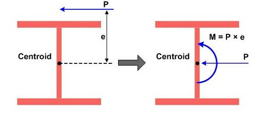
Figuur 1: Voorbeeld van excentrische belasting op een I-vormige doorsnede
Bron: http://manual.midasuser.com
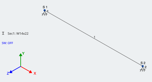
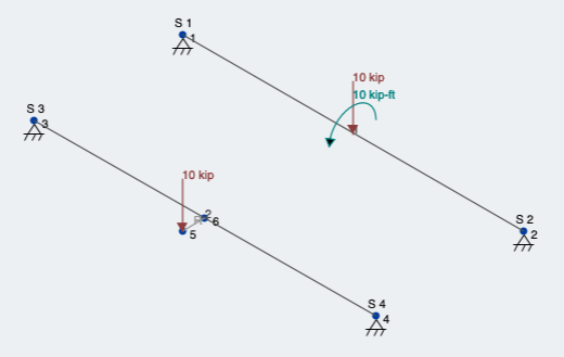
Laten we een voorbeeld bekijken in SkyCiv Structurele 3D en een excentrische puntbelasting op twee verschillende manieren toepassen. Eerste, laten we aannemen dat we een W14x22-balk hebben 15 meter lang met een excentrische puntbelasting in het midden van de overspanning 10 kips, acteren 12 centimeter verwijderd van het zwaartepunt. We nemen aan dat de belasting naar beneden werkt (-Y-richting) en naar de linkerkant (+Z-richting) van het lid. Ook, we gaan ervan uit dat het eigengewicht niet aanwezig is, voor de eenvoud.
Bij het modelleren van één enkel lid, zorg ervoor dat uw steunen correct zijn bij het modelleren van een excentrische belasting. De analyse wordt niet uitgevoerd met beide steunen van uw balkset als 3D-pinnen, omdat geen van beide steunen de rotatie van de dwarsdoorsnede zal weerstaan. In ons geval, de steun verder van de oorsprong is slechts een 2D-pin die rotatie in de X- en Y-richting mogelijk maakt, afkomstig van verticale en horizontale doorbuiging. Laten we eens kijken naar ons voorbeeldelement in de 3D-modelleringsruimte:
Nu, Laten we eens kijken naar de twee methoden om rekening te houden met de excentriciteit van onze lading. Verwijzend naar figuur 1, in ons geval:
\({P.} = {10} kips)
\({e} = 12 inch = 1 voet)
Methode 1: Rekening houden met excentriciteit door een Moment toe te passen
Zoals te zien in figuur 1, we kunnen rekening houden met de excentriciteit van de belasting door een extra moment toe te passen op het zwaartepunt van de staaf. Dit moment wordt gevonden door de puntbelasting te vermenigvuldigen met de momentarm, of “e”. We moeten nog steeds rekening houden met de puntbelasting zelf, dat zal er dus wel zijn (2) ladingen op de geïdentificeerde locatie.
In ons geval:
\({M} = {P.}*{e}\)
\({M} = 10 kips * 1 voet = 10 kip-ft\)
Zoals genoemd, dit moment wordt nu op dezelfde locatie langs de staaf aangebracht als de excentrische puntbelasting. SkyCiv herkent een positief moment als tegen de klok in rond de as die wordt toegepast, wat in ons geval rond de globale X-as ligt. Zie figuur 3 van deze belastingen toegepast in SkyCiv 3D:
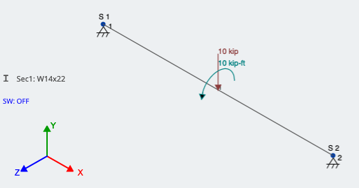
Figuur 3: Modelleren van excentrische belasting door een extra moment toe te passen
Methode 2: Het gebruik van starre verbindingen
Een andere methode is het gebruik van starre verbindingen. Stijve links worden gezien als denkbeeldige leden die roteren en vertalen met waar het ook mee verbonden is. Ze buigen niet af tussen hun knooppunten en zijn volledig stijf. Starre koppelingen worden in de 3D-modelleringsruimte geïdentificeerd als lichtgrijs en hebben een “R” naast hun, zoals te zien in figuur 4. Omdat ze meer worden gebruikt voor het verbinden van elementen en belastingen, ze hebben wel een maat- of sectie-ID nodig.
Voor ons voorbeeld, Knooppunt 6 bevindt zich in het midden van de staaf. Knooppunt 5 bevindt zich op dezelfde X-coördinaat, maar 1.0 voet in de +Z-richting; Knooppunt 5 is de werkelijke locatie van de excentrische belasting.
Maak/teken een lid tussen de twee knooppunten, en wijs deze toe als een starre link. Dit kunt u doen door op de te drukken Geavanceerd schakelen in het ledenvenster, dan gaan we naar Type en verander het in Stijve schakel. Eenmaal toegepast, het lid moet er uitzien zoals hierboven beschreven. Waarbij het ene uiteinde de werkelijke locatie van de excentrische belasting aangeeft en het andere uiteinde in de loodrechte richting met het element is verbonden, de belasting kan eindelijk worden aangebracht. Dit wordt weergegeven in figuur 4; de rode pijl wijst naar de Rigid Link:
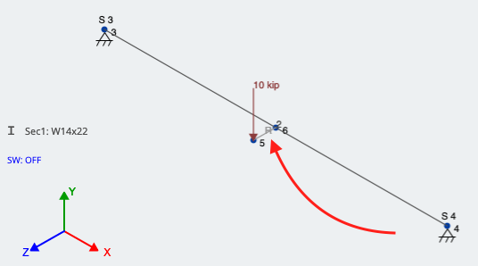
Figuur 4: Een starre verbinding gebruiken om rekening te houden met de excentriciteit van een puntbelasting
Laatste vergelijking en analyse:
Laten we een lineaire statische analyse uitvoeren en de resultaten bekijken. We zouden de neerwaartse kracht ervan moeten zien 10 kips naast een torsiecomponent op de laadlocatie. Beide
Figuur 5: Beide belastingsvoorwaarden voor excentrische belasting
Eerste, laten we eens kijken naar de reactie- en momentresultaten (Figuur 6):
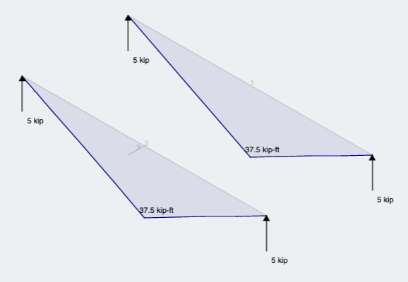
Figuur 6: Reacties en Moment-resultaten voor beide methoden
Zoals verwacht zien we wat we zouden verwachten van een belasting en locatie van dezelfde omvang langs de staaf, maar door het middelpunt.
Hierop volgend, vanwege de excentriciteit, we kunnen waarnemen dat beide leden hetzelfde resultaat opleveren en laten zien dat het lid dat is OOK torsie ervaren (Figuur 7):
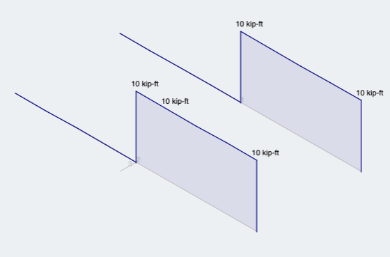
Figuur 7: Resultaten van torsieanalyse voor beide methoden

Bouwkundig ingenieur
BEng (Civiel)