
In stalen verbindingsuitvoering, bouten zijn meestal ontworpen als een boutgroep die als één lichaam fungeert om een bepaalde belasting te weerstaan. De sterkte van een boutgroep wordt normaal gesproken bepaald door de controlerende sterkte van de meest kritische bout. De directe belastingen worden verdeeld over het totale aantal bouten, terwijl het geïnduceerde moment als gevolg van de excentriciteit van de belasting wordt verdeeld in verhouding tot het traagheidsmoment van de boutgroep en de afstand tot het zwaartepunt. Dit heet elastische analyse. Vanwege de vereenvoudigde en conservatieve aannames over de verdeling van de belasting, het levert vaak overontworpen boutverbindingen op.
Als we het hebben over value engineering en economische ontwerpen, de inelastische benadering heeft de voorkeur van de meeste fabrikanten. Er zijn minder bouten nodig voor dezelfde belasting. Om de inelastische benadering te doen, het momentane rotatiecentrum (ICOR) methode met behulp van iteraties is de beste manier.
In dit artikel, we laten zien hoe je de sterkte van a kunt berekenen geboute verbinding volgens de ICOR-methode. De reacties per bout worden berekend met behulp van vergelijking (7-1) op pagina 7-7 van de AISC 15e editie-handleiding. Daarmee wordt vervolgens gecontroleerd of de veronderstelde locatie van het momentane middelpunt van de boutgroep juist is. Uiteindelijk, zodra we de juiste IC-locatie hebben, we berekenen de boutgroepcoëfficiënt C om de sterkte ervan te bepalen.
Met de hand gewerkt, de ICOR-methode is een lang proces, omdat het vinden van het momentane centrum (IC) is vallen en opstaan. Met een computeroplosser wordt het IC van een boutgroep gevonden door geprogrammeerde iteraties. De SkyCiv Bolt Group-oplosser gebruikt een snelle iteratiemethode om de IC-locatie en de boutgroepcoëfficiënt in seconden te bepalen. Het wordt gebruikt door zowel de AISC als AS 4100 aansluitmodules.
Het uitgewerkte voorbeeld hieronder is dezelfde berekening die de oplosser uitvoert, met de lange hand weergegeven, zodat u kunt volgen wat hij doet.
De eigenschappen van de boutgroep verkrijgen
Laten we beginnen met een eenvoudige analyse van een boutgroep van vier bouten belast met een excentrische verticale schuifbelasting van 10 kips. De excentriciteit van de belasting langs de x-as is 4 inches rechts van de boutgroep. De hoek vanaf de verticaal is nul en de excentriciteit langs de y-as is nul.
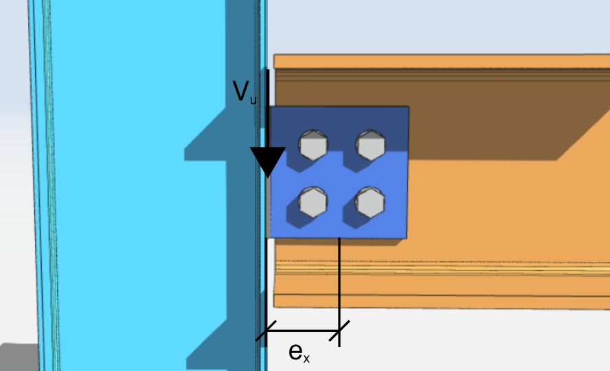
[math] V_{u} = 10\,kips [math]
[math] \theta = 0\,deg [math]
[math] e_{x} = 4\,in [math]
[math] e_{y} = 0\,in [math]
Het eerste dat u moet doen, is de coördinaten van alle bouten in de groep verkrijgen. Visuele hulplijnen en tabellen worden ten zeerste aanbevolen.
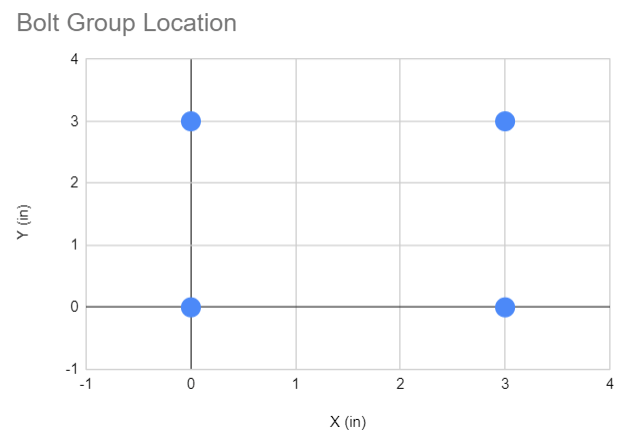
| Winkel-ID | X (in) | EN (in) |
| 1 | 0 | 0 |
| 2 | 0 | 3 |
| 3 | 3 | 0 |
| 4 | 3 | 3 |
Om het zwaartepunt van de boutgroep langs de x- en y-as te verkrijgen, we hebben de onderstaande formule nodig.
Laten [mathin] n [mathin] = totaal aantal bouten
[math] X_{CG} = \frac{\sum X}{n} [math]
[math] Y_{CG} = \frac{\sum Y}{n} [math]
Vervolgens, onze oplossing is::
[math] X_{CG} = \frac{\sum X}{n} = \frac{0\,in + 0\,in + 3\,in + 3\,in}{4} = 1.5\,in [math]
[math] Y_{CG} = \frac{\sum Y}{n} = \frac{0\,in + 3\,in + 0\,in + 3\,in}{4} = 1.5\,in [math]
Neem de locatie van de I.C.
Na het krijgen van het zwaartepunt, we nemen de locatie van het momentane centrum aan (IC). Als eerste poging, we kunnen aannemen dat de IC zich in het geometrische zwaartepunt van de boutgroep bevindt.
Dus, aannemen
[math] X_{IC} = X_{CG} = 1.5\,in [math]
[math] Y_{IC} = Y_{CG} = 1.5\,in [math]
Vervolgens brengen we de verplaatsing van elke bout van het IC in kaart. Bereken eerst de afstand langs x en de afstand langs y, dan de resulterende verplaatsing.
| Winkel-ID | cx (in) | cy (in) | c (in) |
| 1 | -1.5 | -1.5 | 2.121 |
| 2 | -1.5 | 1.5 | 2.121 |
| 3 | 1.5 | -1.5 | 2.121 |
| 4 | 1.5 | 1.5 | 2.121 |
Waarbij,
[math] c_{x} = X_{i} – X_{IC} [math]
[math] c_{y} = Y_{i} – Y_{IC} [math]
[math] c = \sqrt{ {\left( c_{x} \right)}^{2} + {\left( c_{y} \right)}^{2} } [math]
Voor bout nr. 1, onze oplossing is:
[math] c_{x} = 0\,in – 1.5\,in = -1.5\,in [math]
[math] c_{y} = 0\,in – 1.5\,in = -1.5\,in [math]
[math] c = \sqrt{ {\left( -1.5\,in \right)}^{2} + {\left( -1.5\,in \right)}^{2} } = 2.121\,in [math]
Bereken de vervorming per bout tov afstand van IC
Na het verkrijgen van de boutafstanden vanaf de veronderstelde IC-locatie, we berekenen de vervorming van elke bout als functie van de afstand.
De maximale vervorming per bout, [mathin] \Delta_{max} = 0.34\,in [mathin], is gebaseerd op experimentele gegevens voor een ASTM-bout zoals beschreven op de AISC-pagina 7-8. Volgens lineaire proporties, en instelling [mathin] \Delta_{max} = 0.34\,in [mathin], we kunnen de vervorming van een individuele bout berekenen in verhouding tot zijn aandeel in de maximale afstand [mathin] c_{max} [mathin]. De vergelijking voor het krijgen van [mathin] \Delta [mathin] wordt hieronder weergegeven:.
[math] \Delta_{1} = 0.34\,in \times \left( \frac{c}{c_{max}} \right) [math]
Voor bout nr. 1, de vervorming is
[math] \Delta_{1} = 0.34\,in \times \left( \frac{2.121\,in}{2.121\,in} \right) = 0.34\,in [math]
Omdat de IC in het zwaartepunt werd verondersteld, alle vier de bouten bevinden zich op dezelfde afstand ervan, dus alle vier bereiken dezelfde vervorming. De berekende vervormingen worden hieronder weergegeven.
| Winkel-ID | [mathin] \Delta [mathin] (in) |
| 1 | 0.34 |
| 2 | 0.34 |
| 3 | 0.34 |
| 4 | 0.34 |
Krijg de reacties per bout
Zodra we de vervorming per bout hebben:, wij gebruiken AISC 15e Ed. Eq (7-1) om de reacties per bout te krijgen.
[math] R = R_{ult} \left( 1 – e^{-10\Delta} \right)^{0.55} [math]
De [mathin] R_{ult} [mathin] in de vergelijking is de veronderstelde uiteindelijke belasting op een bout, die we kunnen instellen als de afschuifsterkte van de bout.
[math] R_{ult} = \phi R_{n} [math]
Voor ons voorbeeld, Wij hanteren een boutschuifsterkte van [mathin] 24.4\,kip [mathin]. Een andere waarde is even geldig, omdat deze teniet wordt gedaan als we de boutgroepcoëfficiënt berekenen [mathin] C [mathin] later.
Voor bout nr. 1, de berekende reactie is
[math] R = R_{ult} \left( 1 – e^{-10\Delta} \right)^{0.55} [math]
[math] R = 24.4\,kip \left( 1 – e^{-10 \times \left( 0.34\,in \right)} \right)^{0.55} [math]
[math] R = 23.949\,kip [math]
Voor de rest van de bouten, de berekende reacties zijn als volgt:. De componenten van de boutreactie [mathin] R [mathin] langs x en y worden ook getoond.
| Winkel-ID | R (kip) | Rx (kip) | Ry (kip) |
| 1 | 23.949 | 16.937 | -16.937 |
| 2 | 23.949 | -16.937 | -16.937 |
| 3 | 23.949 | 16.937 | 16.937 |
| 4 | 23.949 | -16.937 | 16.937 |
| ⅀Rx = 0 | Ry = 0 |
Elke boutkracht werkt loodrecht op de lijn die die bout met het IC verbindt, dat is wat het teken van de twee componenten bepaalt. Voor Bout No.1, de oplossingen voor de x- en y-componenten worden hieronder weergegeven.
[math] R_{x} = -R \left( \frac{c_{y}}{c} \right) = -23.949 \times \left( \frac{-1.5\,in}{2.121\,in} \right) = 16.937\,kip [math]
[math] R_{y} = R \left( \frac{c_{x}}{c} \right) = 23.949 \times \left( \frac{-1.5\,in}{2.121\,in} \right) = -16.937\,kip [math]
Vervolgens hebben we het moment nodig dat elke boutreactie produceert rond het IC. Gebruik de componenten [mathin] R_{x} [mathin] en [mathin] R_{y} [mathin] met de hefboomarmen [mathin] c_{y} [mathin] en [mathin] c_{x} [mathin].
[math] M_{r} = -R_{x} c_{y} + R_{y} c_{x} [math]
Voor Bout No.1, het moment dat de reactie over de IC is
[math] M_{r} = -16.937\,kip \times \left( -1.5\,in \right) + \left( -16.937\,kip \right) \times \left( -1.5\,in \right) [math]
[math] M_{r} = 50.811\,kip\text{-}in [math]
Als cheque, hetzelfde moment is [mathin] R \times c = 23.949 \times 2.121 = 50.8\,kip\text{-}in [mathin], omdat de kracht loodrecht op de straal staat.
Elke bout bevindt zich hier op dezelfde afstand van het veronderstelde IC en heeft dezelfde kracht, dus elke bout keert op hetzelfde moment terug. De momentreacties worden hieronder weergegeven.
| Winkel-ID | Dhr (kip-in) |
| 1 | 50.811 |
| 2 | 50.811 |
| 3 | 50.811 |
| 4 | 50.811 |
| ⅀Mr = 203.244 |
De IC-locatie verifiëren
Nu we de afschuif- en momentreacties per bout hebben, we gebruiken ze om de belasting te bepalen die deze boutgroep kan weerstaan. Neem de resultante van de som van alle reacties langs x en de som van alle reacties langs y.
Uit het vorige gedeelte, dat hebben wij berekend
[math] \sum R_{x} = 0\,kip [math]
en
[math] \sum R_{y} = 0\,kip [math]
Dus,
[math] P_{u} = \sqrt{ {\left( \sum R_{x} \right)}^{2} + {\left( \sum R_{y} \right)}^{2} } = 0\,kip [math]
De resulterende belasting is [mathin] P_{u} = 0\,kip [mathin]. Een groep bouten die om zijn eigen zwaartepunt draait, draagt puur moment en geen netto kracht met zich mee, dus het kan de toegepaste afschuiving niet weerstaan. Dat vertelt ons al dat de eerste veronderstelde IC-locatie verkeerd is, en we zouden hier kunnen stoppen. Voor het doel van deze discussie, we zullen doorgaan met de resterende stappen.
[math] P_{ux} = -P_{u}\sin\left( \theta \right) = 0\,kip [math]
[math] P_{uy} = -P_{u}\cos\left( \theta \right) = 0\,kip [math]
[math] M_{u} = -P_{ux}\left( Y_{CG} + e_{y} – Y_{IC} \right) + P_{uy} \left( X_{CG} + e_{x} – X_{IC} \right) = 0\,kip\text{-}in [math]
Sinds,
[math] P_{ux} \neq \sum R_{x} [math]
[math] P_{uy} \neq \sum R_{y} [math]
[math] M_{u} \neq \sum M_{r} [math]
Het toegepaste moment is nul, terwijl de boutreacties optellen 203.244 kip-in, dus het evenwicht is niet vervuld. De veronderstelde locatie van de I.C. is onjuist, en we gaan naar de volgende veronderstelde locatie.
SkyCiv heeft de berekening van de boutgroep ingebouwd in de verbindingsontwerpmodules. Wilt u onze software voor het ontwerpen van verbindingen uitproberen?
Tweede iteratie
Voor onze tweede iteratie, laten we aannemen dat de I.C. bevindt zich op de onderstaande coördinaten. Omdat de belasting een neerwaartse schuifkracht is die rechts van de groep wordt uitgeoefend, het echte IC ligt links van het zwaartepunt, dus het proces beweegt zich in die richting.
Aannemen
[math] X_{IC} = 0.062\,in [math]
[math] Y_{IC} = 1.5\,in [math]
Herhaal vervolgens de stappen uit de eerste iteratie. Onderstaande tabel toont de coördinaten, de afstand van elke bout tot de veronderstelde I.C., en de overeenkomstige vervorming ten opzichte van die afstand.
| Winkel-ID | X (in) | EN (in) | cx (in) | cy (in) | c (in) | [mathin] \Delta [mathin] (in) |
| 1 | 0 | 0 | -0.062 | -1.5 | 1.501 | 0.155 |
| 2 | 0 | 3 | -0.062 | 1.5 | 1.501 | 0.155 |
| 3 | 3 | 0 | 2.938 | -1.5 | 3.299 | 0.34 |
| 4 | 3 | 3 | 2.938 | 1.5 | 3.299 | 0.34 |
Deze keer bevinden de bouten zich niet allemaal op dezelfde afstand van het IC, dus alleen het verre paar bereikt de 0.34 binnen de limiet. Het dichtstbijzijnde paar vervormt minder en draagt daarom minder belasting.
Merk op dat het berekende zwaartepunt van de bout groep is onveranderd, omdat de boutcoördinaten niet zijn verplaatst.
[math] X_{CG} = 1.5\,in [math]
[math] Y_{CG} = 1.5\,in [math]
Vervolgens berekenen we de reacties langs x, de reacties langs y, en het bijbehorende moment. De waarden zijn hieronder weergegeven:.
| Winkel-ID | R (kip) | Rx (kip) | Ry (kip) | Dhr (kip-in) |
| 1 | 21.4 | 21.4 | -0.9 | 32.1 |
| 2 | 21.4 | -21.4 | -0.9 | 32.1 |
| 3 | 23.9 | 10.9 | 21.3 | 79.0 |
| 4 | 23.9 | -10.9 | 21.3 | 79.0 |
| ⅀Rx = 0 | Ry = 41 | ⅀Mr = 222 |
De volgende, we bepalen de resulterende belasting van alle reacties langs x en y.
[math] P_{u} = \sqrt{ {\left( \sum R_{x} \right)}^{2} + {\left( \sum R_{y} \right)}^{2} } [math]
[math] P_{u} = \sqrt{ {\left( 0\,kip \right)}^{2} + {\left( 40.703\,kip \right)}^{2} } [math]
[math] P_{u} = 40.703\,kip [math]
Vervolgens de componenten van de resulterende belasting, gebaseerd op het gegeven [mathin] \theta [mathin], worden hieronder weergegeven.
[math] P_{ux} = -P_{u}\sin\left( \theta \right) = -41\,kip \times \sin\left( 0\,deg \right) = 0\,kip [math]
[math] P_{uy} = -P_{u}\cos\left( \theta \right) = -41\,kip \times \cos\left( 0\,deg \right) = -41\,kip [math]
Vervolgens gebruiken we deze componenten om de huidige belasting op te lossen over de veronderstelde I.C.
[math] M_{u} = -P_{ux} \left( Y_{CG} + e_{y} – Y_{IC} \right) + P_{uy} \left( X_{CG} + e_{x} – X_{IC} \right) [math]
[math] M_{u} = -0\,kip \left( 1.5\,in + 0\,in – 1.5\,in \right) + \left( -41\,kip \right) \left( 1.5\,in + 4\,in – 0.062\,in \right) [math]
[math] M_{u} = -222\,kip\text{-}in [math]
De volgende, laten we de berekende vergelijken [mathin] P_{ux} [mathin], [mathin] P_{uy} [mathin] en [mathin] M_{u} [mathin] tegen de reacties van de boutgroep.
[math] P_{ux} \approx -\sum R_{x} [math]
[math] P_{uy} \approx -\sum R_{y} [math]
[math] M_{u} \approx -\sum M_{r} [math]
Numeriek gezien wel 0 tegen 0, -41 kip tegen -41 kip, en -222 kip-in tegen -222 kip-in. De linkerkant ligt zo dicht bij de rechterkant dat we de veronderstelde locatie van de I.C. als correct.
In de praktijk blijft de oplosser het proef-IC verplaatsen totdat deze drie residuen binnen een tolerantie vallen, in plaats van te stoppen bij een visuele match.
Oplossen voor C-coëfficiënt
Zodra de I.C. locatie is bepaald, we kunnen de boutgroepcoëfficiënt C verkrijgen met de onderstaande formule.
[math] C = \frac{P_{u}}{\phi R_{n}} = \frac{40.703\,kip}{24.4\,kip} = 1.668 [math]
De coëfficiënt betekent dat de groep draagt 1.668 keer de sterkte van een enkele bout. Merk op dat dit ruim onder de vier aanwezige bouten zit, omdat de excentriciteit de groep het grootste deel van zijn nominale capaciteit kost. Het is ook waar de keuze uit bestaat [mathin] R_{ult} [mathin] annuleert, Daarom kan in het begin elke consistente waarde worden gebruikt.
Gratis boutgroepcalculator
Bekijk hoe wij onze boutverbindingen met deze aanpak ontwerpen in de verbindingsontwerpmodule. Kies een boutverbinding, stel de boutindeling en de excentriciteit in, en het rapport geeft de IC-locatie en de C-coëfficiënt samen met elke andere controle. Het draait in de browser, zonder iets te installeren.
Voor meer functionaliteit, inclusief het opslaan en opnieuw laden van uw bestanden, meld u aan voor een gratis account.
