
De in dit artikel genoemde stalen verbindingen zijn ontworpen in overeenstemming met de Australian Standard ALS 4100:2020, Verbindingshandboek van het Australian Steel Institute 1, en ontwerpgidsen van het Australian Steel Institute 1-5.
Reikwijdte van de AS 4100 Module
Voordat u de verbindingstypen doorneemt, het is de moeite waard om duidelijk te zijn over wat de module onder AS dekt 4100.
ALS 4100:2020 ontwerp in SkyCiv is voor afschuifverbindingen tussen I-secties, in metrische eenheden. Momentverbindingen, splitsingen en verstevigingsverbindingen liggen buiten de huidige AS 4100 domein.
Universele balk naar universele kolom
Ligger-kolomverbindingen behoren tot de meest voorkomende verbindingstypen in staalontwerpen. De AS-verbindingen in SkyCiv zijn gebouwd rond een ondersteunde balkframe in een ondersteunend element, en de oriëntatie kan worden ingesteld op een kolomflenssteun, een kolomwebondersteuning, of een liggerwebsteun.
Die derde oriëntatie betekent dat dezelfde vier verbindingstypen ook van straal tot straal kunnen worden gebruikt, niet alleen van ligger tot kolom.
Er kan slechts één verbinding met een knooppunt tegelijk worden ontworpen. Als het gaat om back-to-back-verbindingen, het is raadzaam om conservatieve aannames te doen over het belastingspad.
Afschuifverbindingen
Een schuifverbinding is een eenvoudige verbinding. Het is gedetailleerd om de eindreactie van de ligger over te dragen en om bij de verbinding te roteren in plaats van om het eindmoment over te dragen, dat is wat het scheidt van een momentverbinding. In de AS-module is deze alleen ontworpen voor afschuiving, zonder gelijktijdige axiale belasting.
Voor het AS-ontwerp, de volgende afschuifverbindingstypen zijn beschikbaar:
Elk van de vier is beschikbaar als ligger-kolomflens, ligger naar kolomlijf, en straal tot straal web.
-

- Webzijplaat – Balk naar Kolom Flens
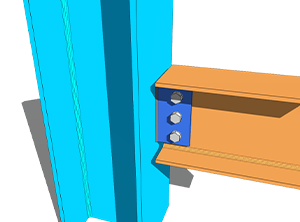
-
- Webzijplaat – Web van straal naar kolom
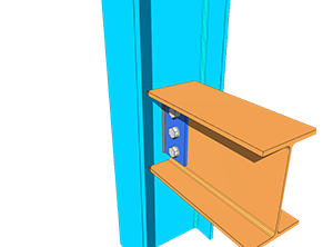
-
- Flexibele eindplaat – Balk naar Kolom Flens

-
- Flexibele eindplaat – Web van straal naar kolom
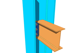
-
- Enkele hoek – Balk naar Kolom Flens
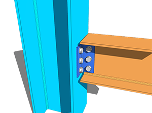
-
- Enkele hoek – Web van straal naar kolom
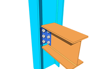
-
- Dubbele hoek – Balk naar Kolom Flens
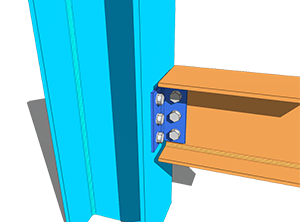
-
- Dubbele hoek – Web van straal naar kolom
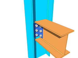
Het ontwerp van de bovenstaande afschuifverbindingen was voornamelijk gebaseerd op ASI Design Guides 3, 4 en 5. De referentieformules zijn overgenomen uit de AS 4100:2020 handmatig, terwijl de rest van de berekeningen en criteria uit het ASI Connection Handbook zijn gehaald 1.
Boutgroepcoëfficiënt
Voor flexibiliteit bij de boutopstelling en boutafstand, SkyCiv heeft de ICOR-methode en inelastische analyse aangepast bij het bepalen van de boutgroepcoëfficiënt C, die vervolgens wordt gebruikt om het afschuifvermogen van de boutgroep en het draagvermogen van de bout te berekenen.
De momentane centrum van rotatiemethode (ICOR) gebruikt iteratie om de IC van de boutgroep te lokaliseren. SkyCiv gebruikt zijn eigen oplosser voor deze iteraties. De locatie van het IC wordt meegenomen in de berekeningen, maar de iteraties worden niet getoond, om het rapport beknopt en leesbaar te houden.
De vergelijking die wordt gebruikt om de kracht per bout te berekenen met behulp van de inelastische analyse is gebaseerd op AISC Eq. (7-1) op pagina 7-7 van de AISC 15e editie-handleiding. De vergelijking wordt hieronder weergegeven.
[math] R = R_{ult}\left(1-e^{-10\Delta}\right)^{0.55} [math]
Dit is een methode die is ontleend aan de boutgroepoplosser, geen wijziging van de ontwerpcode. De capaciteiten zelf worden nog gecontroleerd aan AS 4100:2020.
Omdat de capaciteit van de boutgroep de AISC-methode heeft aangepast, de bepalingen voor het bepalen van de ontwerpboutexcentriciteit van de boutgroep volgen ook de tabel 10-9 van de AISC 15e Ed. Dit is van toepassing op SkyCiv's AS Web Side Plate-verbinding.
Per type wordt er anders omgegaan met excentriciteit. Voor enkele hoekverbindingen, zowel de NSL- als de OSL-poten zijn ontworpen met excentriciteit van de belasting. Voor dubbele hoekverbindingen, alleen de NSL-poot is excentriciteit ontworpen, aangezien het OSL-been symmetrisch gebalanceerd is rond de krachtlijn. Bij flexibele eindplaatverbindingen is er ook geen excentriciteit, omdat de belasting rechtstreeks op het midden van de boutgroep inwerkt. Elke boutgroep zonder excentriciteit neemt de boutcoëfficiënt C als het totale aantal bouten in de groep.
Armatuurtypen
Elke interface kan worden ingesteld als geschroefd of gelast armatuur, bij de balk en bij de steun.
Voor de vastgeschroefde behuizing, zie de documentatie op bouten; voor de gelaste behuizing, zien lassen.
Beperkingen detailleren
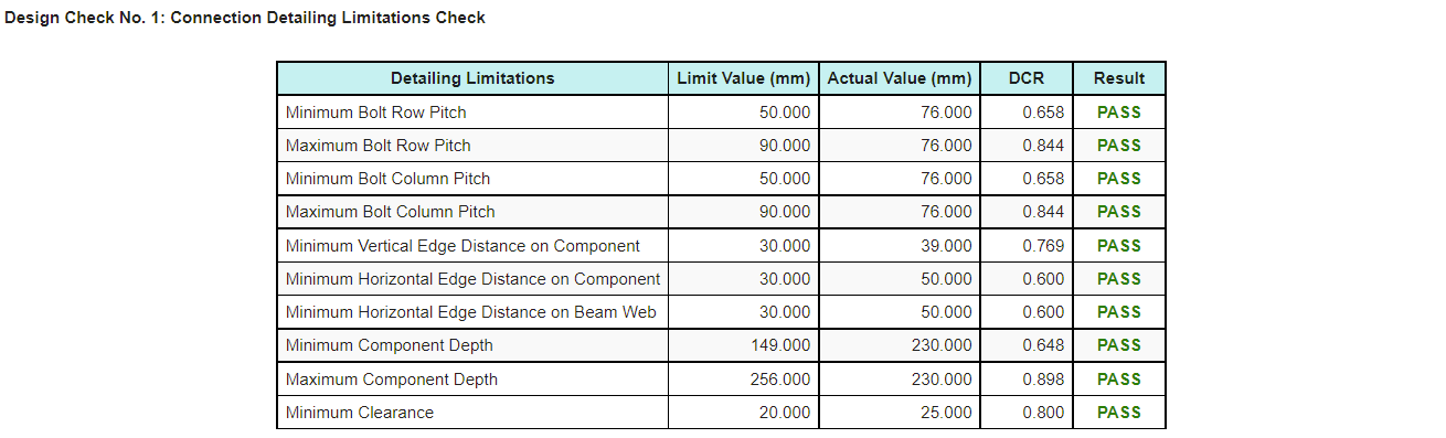
Beperkingen detailleren, de fit-up controles van de verbindingen, zijn opgenomen in het AS-verbindingsontwerp. De meeste zijn gebaseerd op ASI Design Guides 3-5, terwijl sommigen een intuïtieve technische benadering volgen.
Deze controles vangen de verbinding op die aan elke sterkteberekening voldoet en nog steeds niet kan worden gebouwd of opgetrokken, wat een faalwijze is die alleen door krachtcontroles niet kan worden gevonden.
Op het tabblad Resultaten verschijnt een geslaagd of mislukt resultaat voor de detailleringsbeperkingen, zodat het snel kan worden geïdentificeerd. Het rekenrapport levert tevens een tabel op, hieronder weergegeven, zodat het item dat moet worden aangepast gemakkelijk kan worden uitgekozen.
Meer verbindingstypen
Mocht u meer verbindingstypen toegevoegd willen zien onder AS 4100, u kunt contact opnemen SkyCiv-ondersteuning.
Probeer het nu
Kies een webzijplaat, flexibele eindplaat, enkele hoek of dubbele hoek, kom je straal binnen, ondersteuning en lasten, en de module retourneert elke cheque met zijn gebruiksratio en de referentie erachter, samen met de detailleringslimiettabel. Het draait in de browser, zonder iets te installeren, en je kunt het doen zonder account.
U kunt het ook bereiken via de Gratis stalen verbindingsontwerpcalculator.
Aanmelden voor gratis account
Met een gratis account kunt u uw verbindingsbestanden opslaan en opnieuw laden, wat de gratis tool niet doet. Het geeft je ook toegang tot de rest van SkyCiv's structurele software, inclusief Structural 3D.
Verbindingsontwerp standalone
U wilt alleen de verbindingsontwerpmodule gebruiken? Klik op onderstaande knop voor de losse prijzen.
