Base plaatontwerp voorbeeld met behulp van AISC 360-22 en ACI 318-19
Probleemverklaring
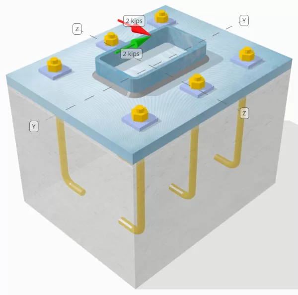
Bepaal of de ontworpen kolom-voetplaatverbinding voldoende is voor een Vy=2-kip en Vz=2-kip schuifbelastingen.
Gegeven gegevens
Kolom:
Kolomgedeelte: HSS7X4X5/16
Kolomgebied: 7.59 in2
Kolommateriaal: A36
Bodemplaat:
Baseplaat afmetingen: 12 in x 14 in
Basisplaatdikte: 3/4 in
Basisplaatmateriaal: A36
Vocht:
Voegdikte: 0.25 in
Beton:
Concrete dimensies: 12 in x 14 in
Betonnen dikte: 10 in
Betonnen materiaal: 3000 psi
Gebarsten of ongescheurd: Gebarsten
Ankers:
Ankerdiameter: 1/2 in
Effectieve inbeddingslengte: 8 in
Dikte van de plaatring: 0.25 in
Aansluiting plaatwasmachine: Gelast aan basisplaat
Lassen:
Lasgrootte: 1/4 in
Vulmetaalclassificatie: E70XX
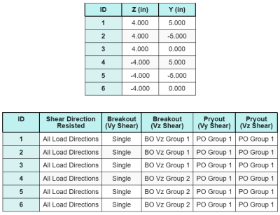
Ankergegevens (van Skyciv Calculator):
Model in SkyCiv Gratis tool
Modelleer vandaag nog het ontwerp van de basisplaat hierboven met onze gratis online tool! Geen aanmelding vereist.
Definities
Pad laden:
Het ontwerp volgt de aanbevelingen van AISC-ontwerpgids 1, 3RD -editie, en ACI 318-19. De op de kolom uitgeoefende schuifbelastingen worden via de lassen overgebracht op de basisplaat, en vervolgens naar het ondersteunende beton via de anker staven. In dit voorbeeld wordt geen rekening gehouden met wrijvings- en afschuifnokken, omdat deze mechanismen niet worden ondersteund in de huidige software.
Standaard, de toegepaste de schuifbelasting wordt over alle ankers verdeeld, hetzij door het gebruik van gelaste plaatringen, hetzij door andere technische middelen. De door elk anker gedragen belasting wordt bepaald met behulp van de drie (3) gevallen vermeld in ACI 318-19 Clausule 17.7.2 en afb. R17.7.2.1b. Elk anker brengt vervolgens de belasting over op het ondersteunende beton eronder. De belastingverdeling in overeenstemming met deze referenties wordt ook gebruikt bij het controleren van de schuifsterkte van het ankerstaal om continuïteit in de aannames van de belastingoverdracht te garanderen.
Als een alternatief, de software maakt een vereenvoudigde en conservatievere aanname mogelijk, waarbij de volledige schuifbelasting alleen wordt toegewezen aan de ankers die zich het dichtst bij de belaste rand bevinden. In dit geval, de controle van de afschuifcapaciteit wordt alleen op deze randankers uitgevoerd.
Ankergroepen:
De SkyCiv-software voor het ontwerpen van grondplaten Bevat een intuïtieve functie die identificeert welke ankers deel uitmaken van een ankergroep om te evalueren uitbraak van betonschaar en beton afschuiving mislukkingen.
Een ankergroep wordt gedefinieerd als twee of meer ankers met overlappende geprojecteerde weerstandsgebieden. In dit geval, de ankers werken samen, en hun gecombineerde weerstand wordt vergeleken met de uitgeoefende belasting op de groep.
A enkel anker wordt gedefinieerd als een anker waarvan het geprojecteerde weerstandsgebied met geen enkel ander anker overlapt. In dit geval, het anker handelt alleen, en de uitgeoefende schuifkracht op dat anker wordt rechtstreeks vergeleken met zijn individuele weerstand.
Door dit onderscheid kan de software zowel groepsgedrag als individuele ankerprestaties vastleggen bij het beoordelen van afschuivingsgerelateerde faalwijzen.
Stapsgewijze berekeningen
Controleren #1: Lascapaciteit berekenen
De eerste stap is het berekenen van de Totale laslengte beschikbaar om weerstand te bieden tegen afschuiving. Omdat de basisplaat langs de omtrek van de kolomsectie is gelast, de totale laslengte wordt verkregen door de lassen aan alle zijden bij elkaar op te tellen.
\( L_{lassen} = 2 \links( b_{col} – 2R_{col} – 2t_{col} \Rechtsaf) + 2 \links( d_{col} – 2R_{col} – 2t_{col} \Rechtsaf) \)
\( L_{lassen} = 2 \keer (4\,\tekst{in} – 2 \maal 0,291,tekst{in} – 2 \maal 0,291,tekst{in}) + 2 \keer (7\,\tekst{in} – 2 \maal 0,291,tekst{in} – 2 \maal 0,291,tekst{in}) = 17.344,tekst{in} \)
Gebruik deze laslengte, de uitgeoefende schuifkrachten in de y- en z-richtingen worden verdeeld om het gemiddelde te bepalen afschuifkracht per lengte-eenheid in elke richting:
\( v_{uy} = frac{V_y}{L_{lassen}} = frac{2\,\tekst{kip}}{17.344\,\tekst{in}} = 0,11531,tekst{kip/in} \)
\( v_{naar} = frac{V_z}{L_{lassen}} = frac{2\,\tekst{kip}}{17.344\,\tekst{in}} = 0,11531,tekst{kip/in} \)
De resulterende afschuiving vraag per lengte-eenheid wordt vervolgens bepaald met behulp van de vierkantswortel van de som van de kwadraten (SRSS) methode.
\( r_u = sqrt{(v_{uy})^ 2 + (v_{naar})^ 2} \)
\( r_u = sqrt{(0.11531\,\tekst{kip/in})^ 2 + (0.11531\,\tekst{kip/in})^ 2} = 0,16308,tekst{kip/in} \)
De volgende, de lascapaciteit wordt berekend met behulp van AISC 360-22 Eq. J2-4, waarbij de richtingssterktecoëfficiënt wordt genomen als kds=1,0 voor een HSS-sectie. De lascapaciteit voor a 1/4 in las wordt bepaald als:
\( \phi r_n = phi 0.6 F_{exx} E_w k_{ds} = 0.75 \keer 0.6 \maal 70,tekst{KSI} \maal 0,177,tekst{in} \keer 1 = 5,5755,tekst{kip/in} \)
Het is ook noodzakelijk om de basismetalen te controleren, zowel de kolom als de basisplaat, gebruik makend van AISC 360-22 Eq. J4-4 om de schuifbreuksterkte te verkrijgen. Dit geeft:
\( \phi r_{nbm, col} = phi 0.6 F_{u_kol} t_{col} = 0.75 \keer 0.6 \maal 58,tekst{KSI} \maal 0,291,tekst{in} = 7,5951,tekst{kip/in} \)
\( \phi r_{nbm, bp} = phi 0.6 F_{u_bp} t_{bp} = 0.75 \keer 0.6 \maal 58,tekst{KSI} \maal 0,75,tekst{in} = 19.575,tekst{kip/in} \)
\( \phi r_{nbm} = minlinks( \phi r_{nbm, bp},\, \phi r_{nbm, col} \Rechtsaf) = min(19.575\,\tekst{kip/in},\, 7.5951\,\tekst{kip/in}) = 7,5951,tekst{kip/in} \)
Omdat de werkelijke lasspanning kleiner is dan de capaciteit van zowel het lasmetaal als het basismetaal, 0.16308 kpi < 5.5755 kpi en 0.16308 kpi < 7.5951 kpi, de ontwerplascapaciteit is voldoende.
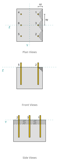
Controleren #2: Bereken het uitbreekvermogen van beton als gevolg van Vy-schuifkracht
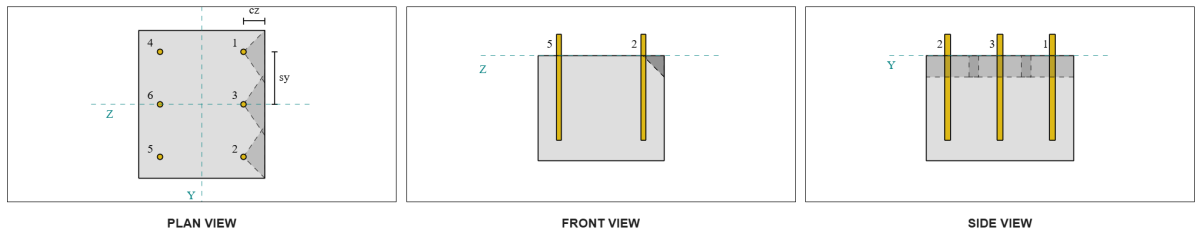
Capaciteit loodrechte rand:
Van de lay-out, Ankers 1 en 4 zijn het dichtst bij de rand en hebben de kortste ca1 afstand. Gebruik deze ca1-waarden om de faalkegels te projecteren, de software identificeerde deze ankers als enkele ankers, omdat hun geprojecteerde kegels elkaar niet overlappen. Er werd ook vastgesteld dat de steun geen smal lid was, dus de ca1-afstand wordt direct en zonder wijziging gebruikt.
Laten we niet vergeten dat wordt aangenomen dat de schuifkracht over alle ankers wordt verdeeld. De berekening voor de Vy schuifbelasting toegepast op elk afzonderlijk anker:
\( V_{faverp} = frac{V_y}{n_a} = frac{2\,\tekst{kip}}{6} = 0,33333,tekst{kip} \)
Laten we eens overwegen Anker 1. Het maximale geprojecteerde oppervlak van een enkel anker wordt berekend met behulp van ACI 318-19 Eq. 17.7.2.1.3.
\( EEN_{Vco} = 4.5 (c_{a1, s1})➔⡔ Koop generieke tadalafil 4.5 \keer (2\,\tekst{in})^2 = 18,tekst{in}^ 2 \)
Het werkelijke geprojecteerde gebied wordt vervolgens bepaald op basis van de breedte en hoogte van de geprojecteerde bezwijkkegel.
\( B_{Vc} = min(c_{links,s1},\, 1.5c_{a1, s1}) + \min(c_{Rechtsaf,s1},\, 1.5c_{a1, s1}) \)
\( B_{Vc} = min(10\,\tekst{in},\, 1.5 \maal 2,tekst{in}) + \min(2\,\tekst{in},\, 1.5 \maal 2,tekst{in}) = 5,tekst{in} \)
\( H_{Vc} = min(1.5c_{a1, s1},\, t_{concerentie}) = min(1.5 \maal 2,tekst{in},\, 10\,\tekst{in}) = 3,tekst{in} \)
\( EEN_{Vc} = B_{Vc} H_{Vc} = 5,tekst{in} \maal 3,tekst{in} = 15,tekst{in}^ 2 \)
De volgende stap is gebruiken Vergelijkingen 17.7.2.2.1a en 17.7.2.2.1b om de fundamentele uitbreeksterkte van een enkel anker te berekenen. Het bestuursvermogen wordt als de lagere waarde genomen.
\( V_{b1} = 7 \links( \frac{\min(de,\, 8d_a)}{d_a} \Rechtsaf)^{0.2} \sqrt{\frac{d_a}{\tekst{in}}} \lambda_a sqrt{\frac{f'_c}{\tekst{psi}}} \links( \frac{c_{a1, s1}}{\tekst{in}} \Rechtsaf)^{1.5} \,\tekst{lbf} \)
\( V_{b1} = 7 \keer links( \frac{\min(8\,\tekst{in},\, 8 \maal 0,5,tekst{in})}{0.5\,\tekst{in}} \Rechtsaf)^{0.2} \keer sqrt{\frac{0.5\,\tekst{in}}{1\,\tekst{in}}} \keer 1 \keer sqrt{\frac{3\,\tekst{KSI}}{0.001\,\tekst{KSI}}} \keer links( \frac{2\,\tekst{in}}{1\,\tekst{in}} \Rechtsaf)^{1.5} \maal 0,001,tekst{kip} \)
\( V_{b1} = 1,1623,tekst{kip} \)
\( V_{b2} = 9 \lambda_a sqrt{\frac{f'_c}{\tekst{psi}}} \links( \frac{c_{a1, s1}}{\tekst{in}} \Rechtsaf)^{1.5} \,\tekst{lbf} \)
\( V_{b2} = 9 \keer 1 \keer sqrt{\frac{3\,\tekst{KSI}}{0.001\,\tekst{KSI}}} \keer links( \frac{2\,\tekst{in}}{1\,\tekst{in}} \Rechtsaf)^{1.5} \maal 0,001,tekst{kip} = 1,3943,tekst{kip} \)
\( V_b = min(V_{b1},\, V_{b2}) = min(1.1623\,\tekst{kip},\, 1.3943\,\tekst{kip}) = 1,1623,tekst{kip} \)
De volgende, de parameters voor uitbreekcapaciteit zijn bepaald. De breakout edge-effectfactor wordt berekend volgens ACI 318-19 Clausule 17.7.2.4, als de diktefactor wordt berekend volgens Clausule 17.7.2.6.1.
\( \Psi_{ed,V } = minlinks(1.0,\, 0.7 + 0.3 \links( \frac{c_{a2,s1}}{1.5c_{a1, s1}} \Rechtsaf) \Rechtsaf) = minlinks(1,\, 0.7 + 0.3 \keer links( \frac{2\,\tekst{in}}{1.5 \maal 2,tekst{in}} \Rechtsaf) \Rechtsaf) = 0.9 \)
\( \Psi_{h,V } = maxlinks( \sqrt{ \frac{1.5c_{a1, s1}}{t_{concerentie}} },\, 1.0 \Rechtsaf) = maxlinks( \sqrt{ \frac{1.5 \maal 2,tekst{in}}{10\,\tekst{in}} },\, 1 \Rechtsaf) = 1 \)
Uiteindelijk, ACI 318-19 Clausule 17.7.2.1(een) wordt gebruikt om het uitbreekvermogen van een enkel anker bij afschuiving te bepalen. De berekende capaciteit voor Vy-afschuiving in de loodrechte richting is 0.69 kips.
\( \phi V_{cbperp} = phi links( \frac{EEN_{Vc}}{EEN_{Vco}} \Rechtsaf) \Psi_{ed,V } \Psi_{c,V } \Psi_{h,V } V_b \)
\( \phi V_{cbperp} = 0.65 \keer links( \frac{15\,\tekst{in}^ 2}{18\,\tekst{in}^ 2} \Rechtsaf) \keer 0.86 \keer 1 \keer 1 \maal 1,1623,tekst{kip} = 0,56661,tekst{kip} \)
De berekende capaciteit voor Vy afschuiving hebben we in de loodrecht richting is 0.56 kips.
Capaciteit parallelle randen:
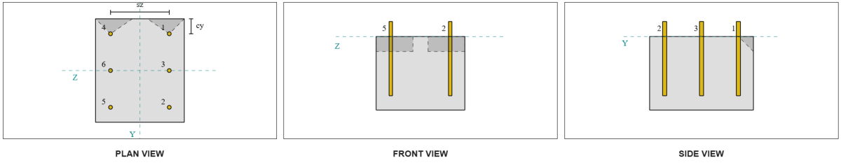
Ook in dit scenario is bezwijken langs de rand evenwijdig aan de belasting mogelijk, dus de betonuitbreekcapaciteit voor de parallelle rand moet worden bepaald. De ankers of ankergroepen die in aanmerking worden genomen, zijn de ankers of ankergroepen die zijn uitgelijnd met de parallelle rand. bijgevolg, de ca1 De randafstand wordt gemeten vanaf het anker tot de rand langs de Z-richting. Gebaseerd op onderstaande figuur, de projecties van de faalkegel overlappen elkaar; daarom, de ankers worden als een groep behandeld.
Geval 1:
Geval 2:
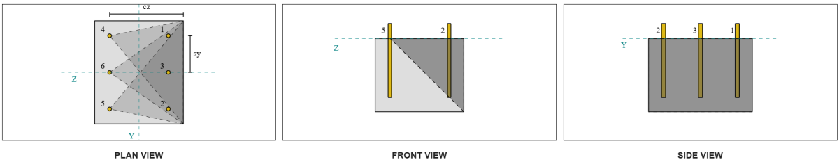
Wij verwijzen naar ACI 318-19 Afb. R17.7.2.1b voor de verschillende gevallen die worden gebruikt bij het evalueren van ankergroepen. In dit basisplaatontwerp, gelaste plaatringen worden specifiek gebruikt. Daarom, enkel en alleen Geval 2 wordt gecontroleerd.
De benodigde belasting voor de ankergroep in Case 2 wordt genomen als de totale schuifbelasting.
\( V_{faparallel,geval2} = V_y = 2,tekst{kip} \)
Bij het berekenen van de capaciteit voor de Case 2 mislukking, de beschouwde ankers zijn de achterste ankers. Als gevolg, de ca1 randafstand wordt gemeten vanaf de achterste ankergroep tot de bezwijkrand.
Met deze ca1 afstand en randoriëntatie, er moet worden nagegaan of de steun kwalificeert als smal element. Volgende ACI 318-19 Clausule 17.7.2.1.2, de SkyCiv Base Plate-software identificeerde de ondersteuning als smal. Daarom, de gewijzigde ca1 afstand is gebruikt, wat berekend wordt 6.667 in.
Dezelfde stappen als in het loodrechte geval worden gevolgd: het berekenen van de geprojecteerde faalgebieden, de basisuitbreeksterkte met één anker, als de breakout-parameters. De berekende waarden voor elke stap worden hieronder weergegeven.
\( EEN_{Vco} = 4.5 (c_{‘a1,g2})➔⡔ Koop generieke tadalafil 4.5 \keer (6.6667\,\tekst{in})^2 = 200,tekst{in}^ 2 \)
\( EEN_{Vc} = B_{Vc} H_{Vc} = 14,tekst{in} \maal 10,tekst{in} = 140,tekst{in}^ 2 \)
\( V_{b1} = 7.0733,tekst{kip} \)
\( V_{b2} = 8.4853,tekst{kip} \)
\( V_b = min(V_{b1},\, V_{b2}) = min(7.0733\,\tekst{kip},\, 8.4853\,\tekst{kip}) = 7.0733,tekst{kip} \)
\( \Psi_{ed,V } = 1.0 \)
\( \Psi_{h,V } = 1.0 \)
De vergelijking voor de parallelle randcapaciteit verschilt van de loodrechte randcapaciteit. ACI 318-19 Clausule 17.7.2.1(c) is toegepast, waar de uitbraakvergelijking is vermenigvuldigd met 2.
\( \phi V_{cbgparallel} = 2 \phi links( \frac{EEN_{Vc}}{EEN_{Vco}} \Rechtsaf) \Psi_{ed,V } \Psi_{c,V } \Psi_{h,V } V_b \)
\( \phi V_{cbgparallel} = 2 \keer 0.65 \keer links( \frac{140\,\tekst{in}^ 2}{200\tekst{in}^ 2} \Rechtsaf) \keer 1 \keer 1 \keer 1 \maal 7.0733,tekst{kip} = 6,4367,tekst{kip} \)
De berekende capaciteit voor Vy afschuiving hebben we in de parallel richting is 6.43 kips.
We beoordelen nu de loodrechte en parallelle breuken afzonderlijk.
- Voor het falen van de loodrechte rand, sinds 0.33 kip < 0.56 kip, het ontwerp van de betonafschuifuitbreekcapaciteit is voldoende.
- Voor de parallelle randstoring, sinds 2 kip < 6.43 kip, het ontwerp van de betonafschuifuitbreekcapaciteit is voldoende.
Controleren #3: Bereken het uitbreekvermogen van beton als gevolg van Vz-schuifkracht
De basisplaat wordt ook onderworpen aan Vz-afschuiving, daarom moeten de bezwijkranden loodrecht en evenwijdig aan de Vz-afschuiving worden gecontroleerd. Met dezelfde aanpak, de loodrechte en parallelle capaciteiten worden berekend als 2.45 kips en 1.26 kips, respectievelijk.
Loodrechte rand:
Parallelle rand:
Deze capaciteiten worden vervolgens vergeleken met de benodigde sterke punten.
- Voor het falen van de loodrechte rand, sinds 2 kip < 2.45 kip, het uitbreekvermogen van beton afschuiving is voldoende.
- Voor de parallelle randstoring, sinds 0.33 kip < 1.26 kip, het uitbreekvermogen van beton afschuiving is voldoende.
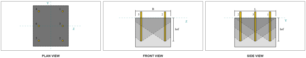
Controleren #4: Bereken het uitbreekvermogen van het beton
De betonnen kegel voor loswrikken is dezelfde kegel die wordt gebruikt bij de doorbraakcontrole op treksterkte. Om het losbreekvermogen te berekenen, Eerst moet de nominale trekuitbreeksterkte van de enkele ankers of ankergroep worden bepaald. De gedetailleerde berekeningen voor de trekuitbraakcontrole worden al behandeld in de SkyCiv-ontwerpvoorbeelden voor trekbelasting.
Het is belangrijk op te merken dat de bepaling van de ankergroep voor het uitbreken van afschuiving anders is dan die voor het uitbreken van afschuiving. Daarom, de ankers in het ontwerp moeten nog worden gecontroleerd om vast te stellen of ze aanwezig zijn handeling heb een door de gebruiker gedefinieerde belastingcombinaties kunnen worden verplaatst naar Sterkte of Onderhoudsgemak of als enkele ankers tegen het falen van de afschuifkracht. De classificatie van de steun als een smal gedeelte moeten ook worden geverifieerd en moeten aan dezelfde voorwaarden voldoen als hiervoor spanning uitbraak.
Uit de SkyCiv-berekeningen, de nominale treksterkte van de ankergroep is 12.772 kips. Met een losbreekfactor van kcp=2, de ontwerp-uitbreekcapaciteit is:
\( \phi V_{cpg} = hy k_{cp} N_{cbg} = 0.65 \keer 2 \keer 12.772 \,\tekst{kip} = 16.604,tekst{kip} \)
De vereiste sterkte is de resultaat van de toegepaste schuifbelastingen. Omdat alle ankers tot één groep behoren, de totale resulterende afschuiving wordt aan de groep toegewezen.
\( V_{Doen} = sqrt{(V_y)^ 2 + (V_z)^ 2} = sqrt{(2\,\tekst{kip})^ 2 + (2\,\tekst{kip})^ 2} = 2,8284,tekst{kip} \)
\( V_{Doen} = links( \frac{V_{Doen}}{n_a} \Rechtsaf) N_{een,G1} = links( \frac{2.8284\,\tekst{kip}}{6} \Rechtsaf) \keer 6 = 2,8284,tekst{kip} \)
Omdat de totale schuifbelasting kleiner is dan de capaciteit van de ankergroep, 2.82 kips < 18.976 kips, de ontwerp-uitbreekcapaciteit is voldoende.
Controleren #5: Bereken de afschuifcapaciteit van de ankerstang
Bedenk dat in dit ontwerpvoorbeeld, De schuifkracht wordt over alle ankers verdeeld. De totale schuifbelasting per anker is dus de resultante van zijn aandeel in de Vy-belasting en zijn aandeel in de Vz-belasting.
\( v_{Doen,j} = frac{V_y}{n_a} = frac{2\,\tekst{kip}}{6} = 0,33333,tekst{kip} \)
\( v_{Doen,z} = frac{V_z}{n_a} = frac{2\,\tekst{kip}}{6} = 0,33333,tekst{kip} \)
\( V_{Doen} = sqrt{(v_{Doen,j})^ 2 + (v_{Doen,z})^ 2} \)
\( V_{Doen} = sqrt{(0.33333\,\tekst{kip})^ 2 + (0.33333\,\tekst{kip})^ 2} = 0,4714,tekst{kip} \)
Dit geeft de schuifspanning op de ankerstang net zo:
\( f_v = frac{V_{Doen}}{EEN_{hengel}} = frac{0.4714\,\tekst{kip}}{0.19635\,\tekst{in}^ 2} = 2.4008,tekst{KSI} \)
Omdat er een platenwasser aanwezig is, een excentrische schuifbelasting wordt geïnduceerd in de ankerstang. De excentriciteit wordt genomen als de helft van de afstand gemeten vanaf de bovenkant van de betonnen steun tot het midden van de plaatring, rekening houdend met de dikte van de basisplaat. Verwijzen naar AISC-ontwerpgids 1, 3sectie van de derde editie 4.3.3.
\( e = 0.5 \links( \frac{t_{pw}}{2} + t_{bp} \Rechtsaf) = 0.5 \keer links( \frac{0.25\,\tekst{in}}{2} + 0.75\,\tekst{in} \Rechtsaf) = 0,4375,tekst{in} \)
Het moment vanaf de excentrische afschuiving wordt dan uitgedrukt als een axiale spanning in de ankerstang. Met behulp van de sectiemodulus, de axiale spanning als gevolg van dit moment wordt berekend als:
\( Z_{hengel} = frac{\pi}{32} (d_a)^3 = frac{\pi}{32} \keer (0.5\,\tekst{in})^3 = 0,012272,tekst{in}^3 \)
\( f_t = frac{V_{Doen} e}{Z_{hengel}} = frac{0.4714\,\tekst{kip} \maal 0,4375,tekst{in}}{0.012272\,\tekst{in}^3} = 16.806,tekst{KSI} \)
ACI ankerstang afschuifcapaciteit:
Volgende ACI 318-19 Clausule 17.7.1, Vervolgens wordt de ontwerpsterkte bepaald. A 0.8 reductiefactor wordt toegepast vanwege de aanwezigheid van voegpads. De ontwerpcapaciteit is dus:
\( \phi V_{naar,hier} = 0.8 \phi 0.6 EEN_{ik weet,v} f_{uta} = 0.8 \keer 0.65 \keer 0.6 \maal 0,1419tekst{in}^2 maal 90tekst{KSI} = 3,9845tekst{kip} \)
Als een alternatief, de SkyCiv-basisplaatsoftware staat de 0.8 vereenvoudiging uitgeschakeld, en gebruik de werkelijke dikte van de voegpads in de berekeningen. In dit geval, de totale excentriciteit omvat het voegkussen, en de gecombineerde schuif- en axiale sterkte wordt bepaald in overeenstemming met de AISC-bepalingen.
AISC-ankerstangafschuifcapaciteit:
Eerste, de nominale schuif- en trekspanningen zijn bepaald voor een A325 hengel.
\( F_{nv} = 0.45 F_{u,anc} = 0.45 \keer 120\ \tekst{KSI} = 54\ \tekst{KSI} \)
\( F_{nt} = 0.75 F_{u,anc} = 0.75 \keer 120\ \tekst{KSI} = 90\ \tekst{KSI} \)
De AISC-methode maakt gebruik van AISC 360-22 Eq. J3-3a, waarbij de effecten van axiale spanning kunnen worden betrokken. Dit wordt als volgt uitgevoerd.
\( F'_{nv} = min links( 1.3 F_{nv} – \links( \frac{F_{nv}}{\phi F_{nt}} \Rechtsaf) f_t,\; F_{nv} \Rechtsaf) \)
\( F'_{nv} = min links( 1.3 \keer 54\ \tekst{KSI} – \links( \frac{54\ \tekst{KSI}}{0.75 \keer 90\ \tekst{KSI}} \Rechtsaf) \keer 16.806\ \tekst{KSI},\; 54\ \tekst{KSI} \Rechtsaf) = 54\ \tekst{KSI} \)
De ontwerpafschuifcapaciteit uit de AISC-methode wordt vervolgens berekend als:
\( \phi R_{n,\wiskunde{aisc}} = phi F’_{nv} EEN_{hengel} = 0.75 \keer 54\ \tekst{KSI} \keer 0.19635\ \tekst{in}➔⡔ Koop generieke tadalafil 7.9522\)
Om ervoor te zorgen dat beide methoden gedekt zijn, de bestuurscapaciteit wordt als de kleinste van de twee beschouwd, dat is 3.98 kip.
\( \phi V_n = min left( \phi V_{naar,hier},\; \phi R_{n,\wiskunde{aisc}} \Rechtsaf) = min (3.9845\ \tekst{kip},\; 7.9522\ \tekst{kip}) = 3.9845\ \tekst{kip} \)
Omdat de schuifbelasting per ankerstaaf kleiner is dan de geldende ankerstaafcapaciteit bij afschuiving, 0.47 kip < 3.98 kip, het ontwerp van de afschuifcapaciteit van de ankerstang is voldoende.
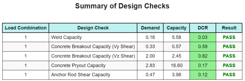
Ontwerp Samenvatting
De Skyciv Base Plate Design Software Kan automatisch een stapsgewijze berekeningsrapport genereren voor dit ontwerpvoorbeeld. Het biedt ook een samenvatting van de uitgevoerde controles en hun resulterende verhoudingen, De informatie in één oogopslag gemakkelijk te begrijpen maken. Hieronder is een sample samenvattende tabel, die is opgenomen in het rapport.
Skyciv Sample Report
Bekijk het detailniveau en de duidelijkheid die u kunt verwachten van een SkyCiv-basisplaatontwerprapport. Het rapport bevat alle belangrijke ontwerpcontroles, vergelijkingen, en resultaten gepresenteerd in een duidelijk en gemakkelijk leesbaar formaat. Het voldoet volledig aan de ontwerpnormen. Klik hieronder om een voorbeeldrapport te bekijken dat is gegenereerd met de SkyCiv-basisplaatcalculator.
Koop baseplaatsoftware
Koop de volledige versie van de basisplaatontwerpmodule op zichzelf zonder andere SkyCiv -modules. Dit geeft u een volledige set resultaten voor het ontwerp van de basisplaat, inclusief gedetailleerde rapporten en meer functionaliteit.