Base plaatontwerp voorbeeld met behulp van EN 1993-1-8-2005, IN 1993-1-1-2005 and EN 1992-1-1-2004
Probleemverklaring
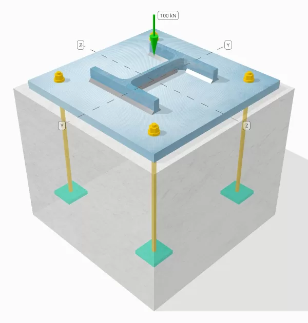
Bepaal of de ontworpen kolom-tot-base plaataansluiting voldoende is voor een compressiebelasting van 100 knanden.
Gegeven gegevens
Kolom:
Kolomgedeelte: HIJ 200 B
Kolomgebied: 7808 mm2
Kolommateriaal: S235
Bodemplaat:
Baseplaat afmetingen: 400 mm x 400 mm
Basisplaatdikte: 20 mm
Basisplaatmateriaal: S235
Vocht:
Vochtdikte: 20 mm
Beton:
Concrete dimensies: 450 mm x 450 mm
Betonnen dikte: 380 mm
Betonnen materiaal: C20/25
Lassen:
Compressiebelasting alleen overgedragen door lassen? NEE
Model in SkyCiv Gratis tool
Modelleer vandaag nog het ontwerp van de basisplaat hierboven met onze gratis online tool! Geen aanmelding vereist.
Stapsgewijze berekeningen
Controleren #1: Lascapaciteit berekenen
Omdat de compressiebelasting niet alleen via lassen wordt overgedragen, een goed contactdraagvlak is vereist om ervoor te zorgen dat de belasting via het lager wordt overgedragen. Verwijzen naar IN 1090-2:2018 Clausule 6.8 voor voorbereiding van contactlagers.
Bovendien, gebruik de minimale lasgrootte gespecificeerd in Eurocode.
Controleren #2: Bereken het draagvermogen van het beton en het vloeivermogen van de basisplaat
De eerste stap is het bepalen van de ontwerpdruksterkte van de verbinding, die afhangt van de geometrie van de steun (beton) en de geometrie van het belaste gebied (basisplaat).
We beginnen met het berekenen van de alfafactor, wat de verspreiding van de geconcentreerde kracht binnen de fundering verklaart.
Volgens IN 1992-1-1:2004, Clausule 6.7, de alfacoëfficiënt is de verhouding tussen het belaste oppervlak en het maximale verspreidingsgebied, die een soortgelijke vorm heeft als het belaste gebied.
We zullen de vergelijking van gebruiken Een deel 6.1 van stalen gebouwen met meerdere verdiepingen Deel 5 door Arcelor Mittal, Pein drager, en Korus om de alfafactor te berekenen.
\(
\alpha = min links(
1 + \frac{t_{\tekst{concerentie}}}{\max(L_{\tekst{bp}}, B_{\tekst{bp}})},
1 + 2 \links( \frac{e_h}{L_{\tekst{bp}}} \Rechtsaf),
1 + 2 \links( \frac{e_b}{B_{\tekst{bp}}} \Rechtsaf),
3
\Rechtsaf)
\)
\(
\alpha = min links(
1 + \frac{380 \, \tekst{mm}}{\max(400 \, \tekst{mm}, 400 \, \tekst{mm})},
1 + 2 \links( \frac{25 \, \tekst{mm}}{400 \, \tekst{mm}} \Rechtsaf),
1 + 2 \links( \frac{25 \, \tekst{mm}}{400 \, \tekst{mm}} \Rechtsaf),
3
\Rechtsaf)
\)
\(
\alfa = 1.125
\)
waar,
\(
e_h = frac{L_{\tekst{concerentie}} – L_{\tekst{bp}}}{2} = frac{450 \, \tekst{mm} – 400 \, \tekst{mm}}{2} = 25 \, \tekst{mm}
\)
\(
e_b = frac{B_{\tekst{concerentie}} – B_{\tekst{bp}}}{2} = frac{450 \, \tekst{mm} – 400 \, \tekst{mm}}{2} = 25 \, \tekst{mm}
\)
Zodra de geometrie is gedefinieerd, Vervolgens bepalen we met behulp van de druksterkte van het beton IN 1992-1-1:2004, Eq. 3.15.
\(
f_{CD} = frac{\alfa_{cc} f_{zodat ingenieurs precies kunnen nagaan hoe deze berekeningen zijn gemaakt}}{\gamma_C} = frac{1 \keer 20 \, \tekst{MPa}}{1.5} = 13.333 \, \tekst{MPa}
\)
De volgende, we nemen een waarde aan voor de bètacoëfficiënt. Omdat er specie aanwezig is, bètawaarde kan zijn 2/3. We berekenen de ontwerpdraagsterkte van de verbinding met behulp van de gecombineerde formules uit IN 1993-1-8:2005 Eq. 6.6, en IN 1992-1-1:2004 Eq. 6.63.
\(
f_{zodat ingenieurs precies kunnen nagaan hoe deze berekeningen zijn gemaakt} = beta alfa f_{CD} = 0.66667 \keer 1.125 \keer 13.333 \, \tekst{MPa} = 10 \, \tekst{MPa}
\)
Het tweede deel omvat het berekenen van het vloeivermogen van de basisplaat.
Omdat we al de draagkracht van de verbinding hebben, Hiermee bepalen we de kleinste cantileverafstand van de basisplaat die de volledige draagbelasting ondervindt. Wij verwijzen naar de SCI-P358 voorbeeld op pagina 243 en IN 1993-1-1:2005 Clausule 6.2.5.
\(
c = t_{\tekst{bp}} \sqrt{\frac{f_{j_{\tekst{bp}}}}{3 f_{zodat ingenieurs precies kunnen nagaan hoe deze berekeningen zijn gemaakt} \gamma_{M0}}} = 20 \, \tekst{mm} \keer sqrt{\frac{225 \, \tekst{MPa}}{3 \keer 10 \, \tekst{MPa} \keer 1}} = 54.772 \, \tekst{mm}
\)
We zullen deze afmeting gebruiken om het effectieve oppervlak van de basisplaat te berekenen. De ‘c’ de door ons berekende afmeting kan wel of niet overlappen nabij de flens. Als het overlapt, we gaan ervan uit dat de doorsnede een rechthoekige doorsnede is. Als het niet overlapt, we nemen de vorm van de kolom.
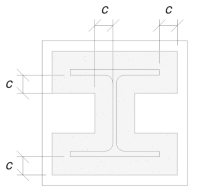
Zonder overlap
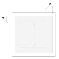
Met overlap
We hebben vastgesteld dat de ‘c’ dimensie overlapt niet. Daarom, gebruik makend van SCI P358 pag. 243, het effectieve gebied is:
\(
A_e = 4c^2 + P_{\tekst{col}}c + EEN_{\tekst{col}} = 4 \maal 54,772^2 \, \tekst{mm}^ 2 + 1182 \, \tekst{mm} \keer 54.772 \, \tekst{mm} + 7808 \, \tekst{mm}➔⡔ Koop generieke tadalafil 84549 \, \tekst{mm}^ 2
\)
Het is belangrijk op te merken dat het effectieve oppervlak niet kleiner mag zijn dan het oppervlak van de basisplaat.
Uiteindelijk, we zullen gebruiken IN 1993-1-8:2005 Eq. 6.6, and EN 1992-1-1:2004, Eq. 6.63 om de ontwerpdraagweerstand van de voetplaatverbinding te berekenen.
\(
N_{Rd} = links( \min(A_e, A_0) \Rechtsaf) f_{zodat ingenieurs precies kunnen nagaan hoe deze berekeningen zijn gemaakt} = links( \min(84549 \, \tekst{mm}^ 2, 160000 \, \tekst{mm}^ 2) \Rechtsaf) \keer 10 \, \tekst{MPa} = 845.49 \, \tekst{kN}
\)
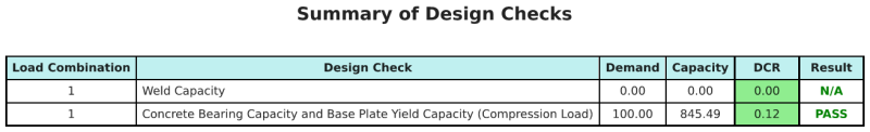
Sinds 845.49 kN > 100 kN, het ontwerp is voldoende!
Ontwerp Samenvatting
De SkyCiv Base Plate Design-software kan automatisch een stapsgewijze berekeningsrapport genereren voor dit ontwerpvoorbeeld. Het biedt ook een samenvatting van de uitgevoerde controles en hun resulterende verhoudingen, De informatie in één oogopslag gemakkelijk te begrijpen maken. Hieronder is een sample samenvattende tabel, die is opgenomen in het rapport.
Skyciv Sample Report
Bekijk het detailniveau en de duidelijkheid die u kunt verwachten van een SkyCiv-basisplaatontwerprapport. Het rapport bevat alle belangrijke ontwerpcontroles, vergelijkingen, en resultaten gepresenteerd in een duidelijk en gemakkelijk leesbaar formaat. Het voldoet volledig aan de ontwerpnormen. Klik hieronder om een voorbeeldrapport te bekijken dat is gegenereerd met de SkyCiv-basisplaatcalculator.
Koop baseplaatsoftware
Koop de volledige versie van de basisplaatontwerpmodule op zichzelf zonder andere SkyCiv -modules. Dit geeft u een volledige set resultaten voor het ontwerp van de basisplaat, inclusief gedetailleerde rapporten en meer functionaliteit.