Ontwerpvoorbeeld van basisplaat met CSA S16:19 en CSA A23.3:19
Probleemverklaring
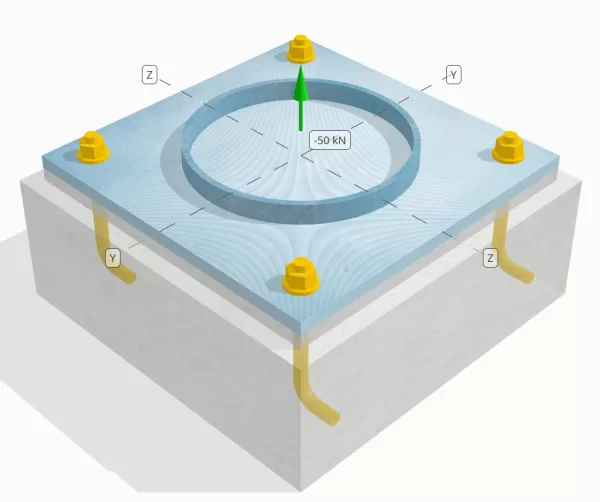
Bepaal of de ontworpen kolom-naar-base plaataansluiting voldoende is voor een spanningsbelasting van 50 knap.
Gegeven gegevens
Kolom:
Kolomgedeelte: HS324X9.5
Kolomgebied: 9410 mm2
Kolommateriaal: 230G
Bodemplaat:
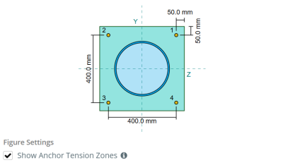
Baseplaat afmetingen: 500 mm x 500 mm
Basisplaatdikte: 20 mm
Basisplaatmateriaal: 230G
Vocht:
Vochtdikte: 20 mm
Beton:
Concrete dimensies: 550 mm x 550 mm
Betonnen dikte: 200 mm
Betonnen materiaal: 20.68 MPa
Gebarsten of ongescheurd: Gebarsten
Ankers:
Ankerdiameter: 19.1 mm
Effectieve inbeddingslengte: 130.0 mm
Haak lengte: 60mm
Offsetafstand van het anker vanaf de voorkant van de kolom: 120.84 mm
Lassen:
Lastype: CJP
Vulmetaalclassificatie: E43XX
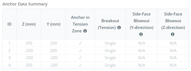
Ankergegevens (van Skyciv Calculator):
Model in SkyCiv Gratis tool
Modelleer vandaag nog het ontwerp van de basisplaat hierboven met onze gratis online tool! Geen aanmelding vereist.
Definities
Pad laden:
Wanneer een grondplaat wordt opgetild (treksterkte) krachten, deze krachten worden overgebracht op de ankerstangen, die op hun beurt buigmomenten in de basisplaat veroorzaken. De buigactie kan worden gevisualiseerd als cantilever buigen die zich voordoen rond de flenzen of het lijf van de kolomsectie, afhankelijk van waar de ankers zijn geplaatst.
In de SkyCiv-software voor het ontwerpen van grondplaten, Alleen ankers in de ankerspanningszone worden als effectief beschouwd bij het weerstaan van opheffing. Deze zone bevat meestal gebieden in de buurt van de kolomflenzen of het web. In het geval van een ronde kolom, de ankerspanningszone omvat het gehele gebied buiten de kolomomtrek. Ankers buiten deze zone dragen niet bij aan spanningsweerstand en zijn uitgesloten van de Uplift -berekeningen.
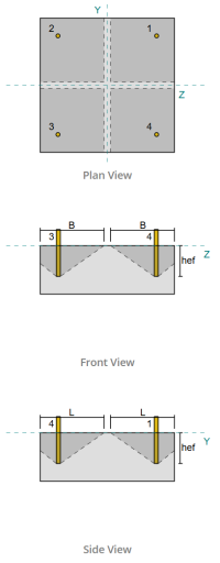
Om het effectieve gebied van de basisplaat te bepalen dat bestand is tegen buigen, een 45-graad spreiding wordt aangenomen vanaf de middellijn van elke ankerstaaf in de richting van het kolomvlak. Deze spreiding definieert de effectieve laslengte en helpt bij het opzetten van de effectieve buigbreedte van de plaat.
De veronderstelling vereenvoudigt de basisplaatanalyse door te benaderen hoe de opheffingskracht zich door de plaat verspreidt.
Ankergroepen:
De SkyCiv-software voor het ontwerpen van grondplaten Bevat een intuïtieve functie die identificeert welke ankers deel uitmaken van een ankergroep om te evalueren beton doorbraak en Concrete zij-gezichtsblaas mislukkingen.
Een ankergroep bestaat uit meerdere ankers met vergelijkbare effectieve inbeddingsdiepten en afstand, en zijn dichtbij genoeg dat hun geprojecteerde weerstandsgebieden overlappen elkaar. Wanneer ankers zijn gegroepeerd, Hun capaciteiten worden gecombineerd om de totale spanningskracht te weerstaan die op de groep wordt uitgeoefend.
Ankers die niet voldoen aan de groeperingscriteria worden behandeld als enkele ankers. In dit geval, Alleen de spanningskracht op het individuele anker wordt gecontroleerd tegen zijn eigen effectieve weerstandsgebied.
Stapsgewijze berekeningen
Controleren #1: Lascapaciteit berekenen
Beginnen, we moeten de belasting per anker berekenen en de effectieve laslengte voor elk anker bepalen. De effectieve laslengte is gebaseerd op een 45° spreidingslijn getrokken vanuit het midden van het anker naar de voorkant van de kolom. Als deze 45°-lijn de kolom niet snijdt, de raakpunten worden in plaats daarvan gebruikt. Bovendien, als de ankers dicht bij elkaar liggen, de effectieve laslengte wordt verminderd om overlapping te voorkomen. Uiteindelijk, de som van alle effectieve laslengten mag niet groter zijn dan de werkelijke lasbare lengte die beschikbaar is langs de kolomomtrek.
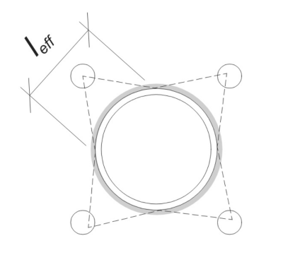
Laten we dit op ons voorbeeld toepassen. Gebaseerd op de gegeven geometrie, de 45°-lijn vanaf het anker snijdt de kolom niet. Als gevolg, in plaats daarvan wordt de booglengte tussen de raakpunten gebruikt. Bij deze booglengte moet ook rekening worden gehouden met eventuele aangrenzende ankers, waarbij eventuele overlappende delen worden afgetrokken om dubbeltellingen te voorkomen. De berekende booglengte is:
\(
l_{\tekst{boog}} = 254.47 \, \tekst{mm}
\)
Deze berekening van de booglengte is volledig geautomatiseerd in de SkyCiv Base Plate Design Software, maar het kan ook handmatig worden uitgevoerd met behulp van trigonometrische methoden. U kunt de gratis tool via deze link uitproberen.
Gezien de beschikbare lasbare lengte langs de omtrek van de kolom, de finale effectieve laslengte is:
\(
l_{\tekst{eff}} = min links( l_{\tekst{boog}}, \frac{\pi d_{\tekst{col}}}{N_{een,t}} \Rechtsaf) = min links( 254.47 \, \tekst{mm}, \frac{\pi \times 324 \, \tekst{mm}}{4} \Rechtsaf) = 254.47 \, \tekst{mm}
\)
De volgende, Laten we de belasting per anker. Voor een gegeven set van vier (4) ankers, de belasting per anker is:
\(
T_{u,\tekst{anker}} = frac{N_x}{N_{een,t}} = frac{50 \, \tekst{kN}}{4} = 12.5 \, \tekst{kN}
\)
Met behulp van de berekende effectieve laslengte, we kunnen nu de benodigde kracht per lengte-eenheid inwerkend op de las.
\(
v_f = \frac{T_{u,\tekst{anker}}}{l_{\tekst{eff}}} = frac{12.5 \, \tekst{kN}}{254.47 \, \tekst{mm}} = 0.049122 \, \tekst{kN / mm}
\)
Nu, wij verwijzen naar CSA S16:19 Clausule 13.13.3.1 om de rekening gehouden met de weerstand van de volledige gewrichtspenetratie (CJP) lassen. Dit vereist de weerstand van het basismetaal, uitgedrukt in kracht per lengte-eenheid, voor zowel de kolom- als de basisplaatmaterialen.
\(
v_{r,\tekst{bm}} = phi links( \min links( F_{j,\tekst{col}} t_{\tekst{col}}, F_{j,\tekst{bp}} t_{\tekst{bp}} \Rechtsaf) \Rechtsaf)
\)
\(
v_{r,\tekst{bm}} = 0.9 \keer links( \min links( 230 \, \tekst{MPa} \keer 9.53 \, \tekst{mm}, 230 \, \tekst{MPa} \keer 20 \, \tekst{mm} \Rechtsaf) \Rechtsaf) = 1.9727 \, \tekst{kN / mm}
\)
Sinds 0.049122 kN / mm < 1.9727 kN / mm, De lascapaciteit is voldoende.
Controleren #2: Bereken de buigcapaciteit van de basisplaat als gevolg van spanningsbelasting
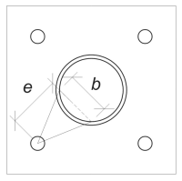
Gebruikmakend van de belasting per anker en de gecompenseerde afstand vanaf het midden van het anker tot aan de voorkant van de kolom, het moment dat op de basisplaat wordt uitgeoefend, kan worden berekend met behulp van a cantilever aanname. Voor een ronde kolom, de excentriciteit van de belasting wordt bepaald door rekening te houden met de sagitta van de lasboog, en kan als volgt worden berekend:
\(
e_{\tekst{pijp}} = d_o + R_{\tekst{col}} \links( 1 – \cos links( \frac{l_{\tekst{eff}}}{2 R_{\tekst{col}}} \Rechtsaf) \Rechtsaf)
\)
\(
e_{\tekst{pijp}} = 120.84 \, \tekst{mm} + 162 \, \tekst{mm} \keer links( 1 – \cos links( \frac{254.47 \, \tekst{mm}}{2 \keer 162 \, \tekst{mm}} \Rechtsaf) \Rechtsaf) = 168.29 \, \tekst{mm}
\)
Het geïnduceerde moment wordt berekend als:
\(
M_f = T_{u,\tekst{anker}} e_{\tekst{pijp}} = 12.5 \, \tekst{kN} \keer 168.29 \, \tekst{mm} = 2103.6 \, \tekst{kN} \cdot tekst{mm}
\)
De volgende, wij bepalen de buigbreedte van de voetplaat. Voor deze, wij gebruiken de akkoord lengte die overeenkomt met de effectieve lasboog.
\(
\theta_{\tekst{rad}} = frac{l_{\tekst{eff}}}{0.5 d_{\tekst{col}}} = frac{254.47 \, \tekst{mm}}{0.5 \keer 324 \, \tekst{mm}} = 1.5708
\)
\(
b = d_{\tekst{col}} \links( \zonde links( \frac{\theta_{\tekst{rad}}}{2} \Rechtsaf) \Rechtsaf) = 324 \, \tekst{mm} \keer links( \zonde links( \frac{1.5708}{2} \Rechtsaf) \Rechtsaf) = 229.1 \, \tekst{mm}
\)
Uiteindelijk, we kunnen de berekenen meegerekend buigweerstand van de basisplaat gebruiken CSA S16:19 Clausule 13.5.
\(
M_r = \phi F_{j,\tekst{bp}} Z_{\tekst{eff}} = 0.9 \keer 230 \, \tekst{MPa} \keer 22910 \, \tekst{mm}^3 = 4742.4 \, \tekst{kN} \cdot tekst{mm}
\)
Waarbij,
\(
Z_{\tekst{eff}} = frac{b (t_{\tekst{bp}})^ 2}{4} = frac{229.1 \, \tekst{mm} \keer (20 \, \tekst{mm})^ 2}{4} = 22910 \, \tekst{mm}^3
\)
Sinds 2103.6 kN-mm < 4742.4 kN-mm, De buigplaten van de basisplaat is voldoende.
Controleren #3: Bereken de trekcapaciteit van de ankerstaaf
Om het trekvermogen van de ankerstang te evalueren, wij verwijzen naar CSA A23.3:19 Clausule D.6.1.2 en CSA S16:19 Clausule 25.3.2.1.
Eerste, We bepalen de gespecificeerde treksterkte van het ankerstaal. Dit is de laagste toegestane waarde CSA A23.3:19 Artikel D.6.1.2.
\(
f_{\tekst{uta}} = min links( F_{u,\tekst{anc}}, 1.9 F_{j,\tekst{anc}}, 860 \Rechtsaf) = min links( 400 \, \tekst{MPa}, 1.9 \keer 248.2 \, \tekst{MPa}, 860.00 \, \tekst{MPa} \Rechtsaf) = 400 \, \tekst{MPa}
\)
De volgende, We bepalen de effectief dwarsdoorsnedeoppervlak van de ankerstang onder spanning met behulp van CAC Handboek voor betonontwerp, 3RD -editie, Tafel 12.3.
\(
EEN_{ik weet,N} = 215 \, \tekst{mm}^ 2
\)
Met deze waarden, We passen toe CSA A23.3:19 Eq. D.2 om de te berekenen berekende trekweerstand van de ankerstang.
\(
N_{\tekst{sar}} = A_{ik weet,N} \phi_s f_{\tekst{uta}} R = 215 \, \tekst{mm}^2 tijden 0.85 \keer 400 \, \tekst{MPa} \keer 0.8 = 58.465 \, \tekst{kN}
\)
Bovendien, We evalueren de berekende trekweerstand volgens CSA S16:19 Clausule 25.3.2.1.
\(
T_r = \phi_{ar} 0.85 EEN_{ar} F_{u,\tekst{anc}} = 0.67 \keer 0.85 \keer 285.02 \, \tekst{mm}^2 tijden 400 \, \tekst{MPa} = 64.912 \, \tekst{kN}
\)
Na het vergelijken van de twee, we stellen vast dat de gefactoriseerde weerstand berekend met behulp van CSA A23.3:19 regeert in dit geval.
Bedenk de eerder berekende spanningsbelasting per anker:
\(
N_{fa} = frac{N_x}{N_{een,t}} = frac{50 \, \tekst{kN}}{4} = 12.5 \, \tekst{kN}
\)
Sinds 12.5 kN < 58.465 kN, De trekcapaciteit van de ankerkam is voldoende.
Controleren #4: Bereken de betonuitbraakcapaciteit in spanning
Voordat u de breakout -capaciteit berekent, We moeten eerst bepalen of het lid in aanmerking komt als een smal lid. Volgens CSA A23.3:19 Artikel D.6.2.3, het lid voldoet niet aan de criteria voor een smal lid. Daarom, the given Effectieve inbeddingslengte will be used in the calculations.
Gebruik makend van CSA A23.3:19 Eq. D.5, we berekenen de maximaal geprojecteerd betonkegeloppervlak voor één enkel anker, based on the effective embedment length.
\(
EEN_{Onthouden} = 9 (h_{ef,s1})➔⡔ Koop generieke tadalafil 9 \keer (130 \, \tekst{mm})➔⡔ Koop generieke tadalafil 152100 \, \tekst{mm}^ 2
\)
Evenzo, we use the effective embedment length to calculate the Werkelijk geprojecteerd betonnen kegelgebied of the single anchor.
\(
EEN_{Nc} = L_{Nc} B_{Nc} = 270 \, \tekst{mm} \keer 270 \, \tekst{mm} = 72900 \, \tekst{mm}^ 2
\)
Waarbij,
\(
L_{Nc} = links( \min links( c_{\tekst{links},s1}, 1.5 h_{ef,s1} \Rechtsaf) \Rechtsaf) + \links( \min links( c_{\tekst{Rechtsaf},s1}, 1.5 h_{ef,s1} \Rechtsaf) \Rechtsaf)
\)
\(
L_{Nc} = links( \min links( 475 \, \tekst{mm}, 1.5 \keer 130 \, \tekst{mm} \Rechtsaf) \Rechtsaf) + \links( \min links( 75 \, \tekst{mm}, 1.5 \keer 130 \, \tekst{mm} \Rechtsaf) \Rechtsaf)
\)
\(
L_{Nc} = 270 \, \tekst{mm}
\)
\(
B_{Nc} = links( \min links( c_{\tekst{top},s1}, 1.5 h_{ef,s1} \Rechtsaf) \Rechtsaf) + \links( \min links( c_{\tekst{bodem},s1}, 1.5 h_{ef,s1} \Rechtsaf) \Rechtsaf)
\)
\(
B_{Nc} = links( \min links( 75 \, \tekst{mm}, 1.5 \keer 130 \, \tekst{mm} \Rechtsaf) \Rechtsaf) + \links( \min links( 475 \, \tekst{mm}, 1.5 \keer 130 \, \tekst{mm} \Rechtsaf) \Rechtsaf)
\)
\(
B_{Nc} = 270 \, \tekst{mm}
\)
De volgende, We evalueren de meegerekend basic concrete breakout resistance van een enkel anker met behulp van CSA A23.3:19 Eq. D.6
\(
N_{br} = k_c \phi \lambda_a \sqrt{\frac{f'_c}{\tekst{MPa}}} \links( \frac{h_{ef,s1}}{\tekst{mm}} \Rechtsaf)^{1.5} R N
\)
\(
N_{br} = 10 \keer 0.65 \keer 1 \keer sqrt{\frac{20.68 \, \tekst{MPa}}{1 \, \tekst{MPa}}} \keer links( \frac{130 \, \tekst{mm}}{1 \, \tekst{mm}} \Rechtsaf)^{1.5} \keer 1 \keer 0.001 \, \tekst{kN} = 43.813 \, \tekst{kN}
\)
Waarbij,
- \(zodat ingenieurs precies kunnen nagaan hoe deze berekeningen zijn gemaakt{c} = 10\) voor ingestorte ankers
- \(\lambda = 1.0 \) voor normaal gewicht beton
Nu, we beoordelen de effecten van geometrie door de randeffectfactor.
De kortste randafstand van de ankergroep wordt bepaald als:
\(
c_{een,\tekst{min}} = min links( c_{\tekst{links},s1}, c_{\tekst{Rechtsaf},s1}, c_{\tekst{top},s1}, c_{\tekst{bodem},s1} \Rechtsaf) = min links( 475 \, \tekst{mm}, 75 \, \tekst{mm}, 75 \, \tekst{mm}, 475 \, \tekst{mm} \Rechtsaf) = 75 \, \tekst{mm}
\)
Volgens CSA A23.3:19 Eq. D.10 and D.11, de uitbraak randeffectfactor is:
\(
\Psi_{ed,N} = min links( 1.0, 0.7 + 0.3 \links( \frac{c_{een,\tekst{min}}}{1.5 h_{ef,s1}} \Rechtsaf) \Rechtsaf) = min links( 1, 0.7 + 0.3 \keer links( \frac{75 \, \tekst{mm}}{1.5 \keer 130 \, \tekst{mm}} \Rechtsaf) \Rechtsaf) = 0.81538
\)
Daarnaast, Beide kraakfactor als de splitsingsfactor worden genomen als:
\(
\Psi_{c,N} = 1
\)
\(
\Psi_{cp,N} = 1
\)
Vervolgens, we combineren al deze factoren en gebruiken ACI 318-19 Eq. 17.6.2.1b om de meegerekend concrete breakout resistance of the single anchor:
\(
N_{cbr} = links( \frac{EEN_{Nc}}{EEN_{Onthouden}} \Rechtsaf) \Psi_{ed,N} \Psi_{c,N} \Psi_{cp,N} N_{br} = links( \frac{72900 \, \tekst{mm}^ 2}{152100 \, \tekst{mm}^ 2} \Rechtsaf) \keer 0.81538 \keer 1 \keer 1 \keer 43.813 \, \tekst{kN} = 17.122 \, \tekst{kN}
\)
Bedenk de eerder berekende spanningsbelasting per anker:
\(
N_{fa} = frac{N_x}{N_{een,s}} = frac{50 \, \tekst{kN}}{4} = 12.5 \, \tekst{kN}
\)
Sinds 12.5 kN < 17.122 kN De betonnen breakout -capaciteit is voldoende.
This concrete breakout calculation is based on Anchor ID #1. The same capacity will apply to the other anchors due to the symmetric design.
Controleren #5: Bereken het pull -outcapaciteit van het anker
Het uittrekvermogen van een anker wordt bepaald door de weerstand aan het ingebedde uiteinde ervan. For hooked anchors, it is dependent on its hook length.
We compute the factored basic anchor pullout resistance per CSA A23.3:19 Eq. D.17.
\(
N_{pr} = Psi_{c,p} 0.9 \phi (f'_c) e_h d_a R = 1 \keer 0.9 \keer 0.65 \keer (20.68 \, \tekst{MPa}) \keer 60 \, \tekst{mm} \keer 19.05 \, \tekst{mm} \keer 1 = 13.828 \, \tekst{kN}
\)
Bedenk de eerder berekende spanningsbelasting per anker:
\(
N_{fa} = frac{N_x}{N_{een,t}} = frac{50 \, \tekst{kN}}{4} = 12.5 \, \tekst{kN}
\)
Sinds 12.5 kN < 13.828 kN, De pull -outcapaciteit van het anker is voldoende.
Controleren #6: Bereken de side-face blowoutcapaciteit in Y-richting
This calculation is not applicable for hooked anchors.
Controleren #7: Bereken side-face blowoutcapaciteit in Z-richting
This calculation is not applicable for hooked anchors.
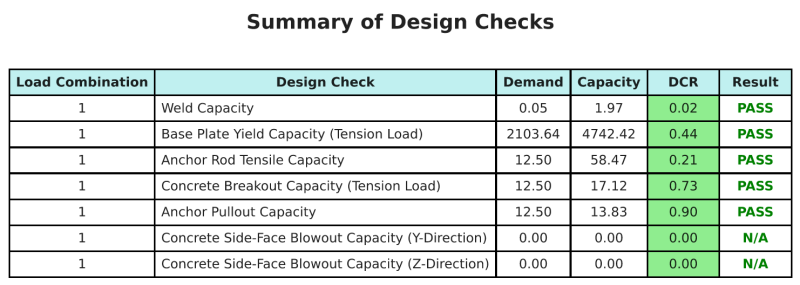
Ontwerp Samenvatting
De Skyciv Base Plate Design Software Kan automatisch een stapsgewijze berekeningsrapport genereren voor dit ontwerpvoorbeeld. Het biedt ook een samenvatting van de uitgevoerde controles en hun resulterende verhoudingen, De informatie in één oogopslag gemakkelijk te begrijpen maken. Hieronder is een sample samenvattende tabel, die is opgenomen in het rapport.
Skyciv Sample Report
Bekijk het detailniveau en de duidelijkheid die u kunt verwachten van een SkyCiv-basisplaatontwerprapport. Het rapport bevat alle belangrijke ontwerpcontroles, vergelijkingen, en resultaten gepresenteerd in een duidelijk en gemakkelijk leesbaar formaat. Het voldoet volledig aan de ontwerpnormen. Klik hieronder om een voorbeeldrapport te bekijken dat is gegenereerd met de SkyCiv-basisplaatcalculator.
Koop baseplaatsoftware
Purchase the full version of the base plate design module onits own without any other SkyCiv modules. Dit geeft u een volledige set resultaten voor het ontwerp van de basisplaat, inclusief gedetailleerde rapporten en meer functionaliteit.