Base plaatontwerp voorbeeld met behulp van As 4100:2020, ALS 3600:2018, ALS 5216:2021
Probleemverklaring
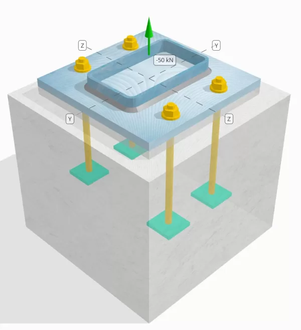
Bepaal of de ontworpen kolom-naar-base plaataansluiting voldoende is voor een spanningsbelasting van 50 knap.
Gegeven gegevens
Kolom:
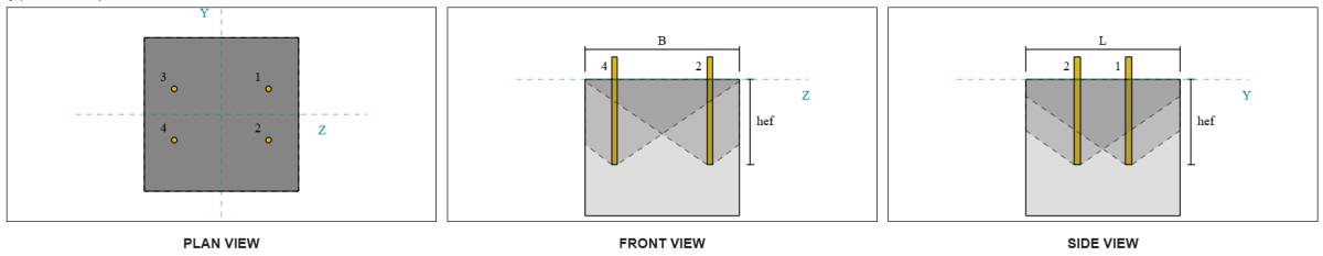
Kolomgedeelte: 250x150x8 RHS
Kolomgebied: 5920 mm2
Kolommateriaal: AS / NZS 1163 GR. C350
Bodemplaat:
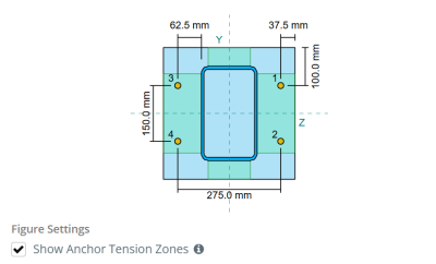
Baseplaat afmetingen: 350 mm x 350 mm
Basisplaatdikte: 20 mm
Basisplaatmateriaal: AS / NZS 1163 GR. C250
Vocht:
Vochtdikte: 20 mm
Beton:
Concrete dimensies: 450 mm x 450 mm
Betonnen dikte: 400 mm
Betonnen materiaal: N28
Gebarsten of ongescheurd: Gebarsten
Ankers:
Ankerdiameter: 16 mm
Effectieve inbeddingslengte: 250.0 mm
Ingebedde plaatbreedte: 70 mm
Ingebedde plaatdikte: 10 mm
Offsetafstand van het anker vanaf de voorkant van de kolom: 62.5 mm
Lassen:
Lastype: Filet
Weld category: SP
Vulmetaalclassificatie: E43XX
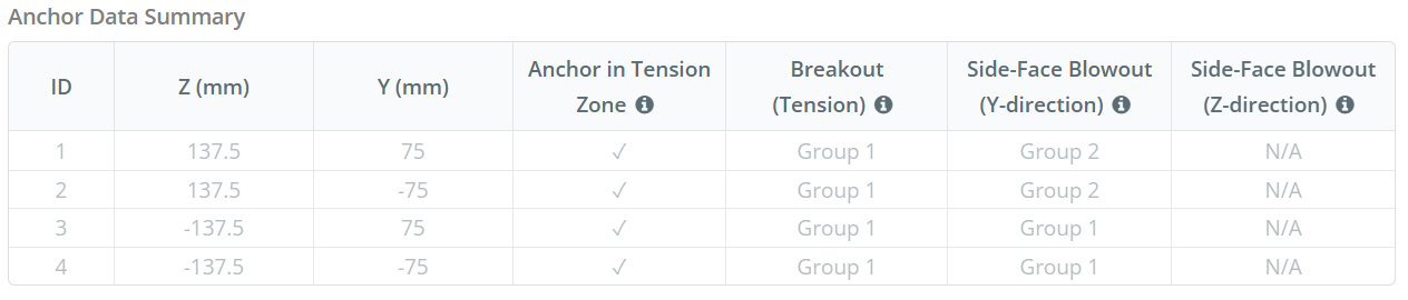
Ankergegevens (van Skyciv Calculator):
Model in SkyCiv Gratis tool
Modelleer vandaag nog het ontwerp van de basisplaat hierboven met onze gratis online tool! Geen aanmelding vereist.
Definities
Pad laden:
Wanneer een grondplaat wordt opgetild (treksterkte) krachten, deze krachten worden overgebracht op de ankerstangen, die op hun beurt buigmomenten in de basisplaat veroorzaken. De buigactie kan worden gevisualiseerd als cantilever buigen die zich voordoen rond de flenzen of het lijf van de kolomsectie, afhankelijk van waar de ankers zijn geplaatst.
In de SkyCiv-software voor het ontwerpen van grondplaten, Alleen ankers in de ankerspanningszone worden als effectief beschouwd bij het weerstaan van opheffing. Deze zone bevat meestal gebieden in de buurt van de kolomflenzen of het web. For rectangular columns, the anchor tension zone refers to the area adjacent to the column walls. Ankers buiten deze zone dragen niet bij aan spanningsweerstand en zijn uitgesloten van de Uplift -berekeningen.
Om het effectieve gebied van de basisplaat te bepalen dat bestand is tegen buigen, een 45-graad spreiding wordt aangenomen vanaf de middellijn van elke ankerstaaf in de richting van het kolomvlak. Deze spreiding definieert de effectieve laslengte en helpt bij het opzetten van de effectieve buigbreedte van de plaat.
De veronderstelling vereenvoudigt de basisplaatanalyse door te benaderen hoe de opheffingskracht zich door de plaat verspreidt.
Ankergroepen:
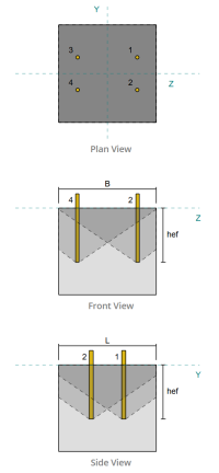
De SkyCiv-software voor het ontwerpen van grondplaten Bevat een intuïtieve functie die identificeert welke ankers deel uitmaken van een ankergroep om te evalueren beton doorbraak en Concrete zij-gezichtsblaas mislukkingen.
Een ankergroep bestaat uit meerdere ankers met vergelijkbare effectieve inbeddingsdiepten en afstand, en zijn dichtbij genoeg dat hun geprojecteerde weerstandsgebieden overlappen elkaar. Wanneer ankers zijn gegroepeerd, Hun capaciteiten worden gecombineerd om de totale spanningskracht te weerstaan die op de groep wordt uitgeoefend.
Ankers die niet voldoen aan de groeperingscriteria worden behandeld als enkele ankers. In dit geval, Alleen de spanningskracht op het individuele anker wordt gecontroleerd tegen zijn eigen effectieve weerstandsgebied.
Prying Increase Factor:
De SkyCiv-software voor het ontwerpen van grondplaten includes an option to apply a prying increase factor to account for additional tensile forces on the anchors due to prying action. This factor increases the load demand on the anchors during the anchor checks, providing a more conservative and realistic assessment where applicable. Standaard, the prying increase factor is set to 1.0, meaning no additional prying load is applied unless specified by the user.
Stapsgewijze berekeningen:
Controleren #1: Lascapaciteit berekenen
Beginnen, we moeten de belasting per anker en de effectieve laslengte per anker berekenen. The effective weld length is determined by the shortest length from the 45° dispersion, beperkt door de werkelijke laslengte en ankerafstand.
Voor deze berekening, ankers worden als een van beide geclassificeerd eind ankers of tussenliggende ankers. Eindankers bevinden zich aan de uiteinden van een rij of kolom ankers, terwijl er tussenliggende ankers tussen zijn geplaatst. De berekeningsmethode verschilt per persoon en is afhankelijk van de kolomgeometrie. In dit voorbeeld, er zijn twee ankers langs het web, en beide zijn geclassificeerd als eindankers.
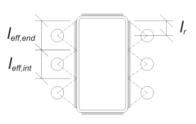
Voor eindankers, the effective weld length is limited by the available distance from the anchor centerline to the column corner radius. De spreiding van 45° mag niet verder reiken dan deze grens.
\(
l_r = frac{d_{col} – 2t_{col} – 2R_{col} – S_ (N_{een,\tekst{⡒🐑⥼ Koop goedkope metoprolol}} – 1)}{2} = frac{250 \, \tekst{mm} – 2 \keer 8 \, \tekst{mm} – 2 \keer 12 \, \tekst{mm} – 150 \, \tekst{mm} \keer (2 – 1)}{2} = 30 \, \tekst{mm}
\)
Aan de binnenkant, de effectieve lengte wordt beperkt door de helft van de ankerafstand. De totale effectieve laslengte voor het eindanker is de som van de buiten- en binnenlengte.
\(
l_{eff,einde} = min links( Doen, 0.5 s_y \right) + \min links( Doen, l_r \right)
\)
\(
l_{eff,einde} = min links( 62.5 \, \tekst{mm}, 0.5 \keer 150 \, \tekst{mm} \Rechtsaf) + \min links( 62.5 \, \tekst{mm}, 30 \, \tekst{mm} \Rechtsaf) = 92.5 \, \tekst{mm}
\)
Voor dit voorbeeld, the final effective weld length for the web anchor is taken as the effective length of the end anchor.
\(
l_{eff} = l_{eff,einde} = 92.5 \, \tekst{mm}
\)
De volgende, let’s calculate the load per anchor. Voor een gegeven set van vier (4) ankers, de belasting per anker is:
\(
T_{u,anker} = frac{N_x}{N_{een,t}} = frac{50 \, \tekst{kN}}{4} = 12.5 \, \tekst{kN}
\)
Met behulp van de berekende effectieve laslengte, we can now compute the required force per unit length acting on the weld.
\(
v^*_ w = frac{T_{u,anker}}{l_{eff}} = frac{12.5 \, \tekst{kN}}{92.5 \, \tekst{mm}} = 0.13514 \, \tekst{kN / mm}
\)
Nu, we zullen gebruiken ALS 4100:2020 Clausule 9.6.3.10 om de ontwerpsterkte van de hoeklas te berekenen.
\(
\Phi v_w = phi 0.6 f_{uw} E_w k_r = 0.8 \keer 0.6 \keer 430 \, \tekst{MPa} \keer 5.657 \, \tekst{mm} \keer 1 = 1.1676 \, \tekst{kN / mm}
\)
In addition to checking the weld, we also need to verify the weerstand van het basismetaal against the applied tension force to ensure it does not govern the failure mode.
\(
\phi v_{wbm} = phi links( \min links( F_{en _col} t_{col}, f_{en _BP} t_{bp} \Rechtsaf) \Rechtsaf)
\)
\(
\phi v_{wbm} = 0.9 \keer links( \min links( 350 \, \tekst{MPa} \keer 8 \, \tekst{mm}, 250 \, \tekst{MPa} \keer 20 \, \tekst{mm} \Rechtsaf) \Rechtsaf) = 2.52 \, \tekst{kN / mm}
\)
In dit geval, the weld resistance governs over the base metal resistance.
Sinds 0.13514 kN / mm < 1.1676 kN / mm, De lascapaciteit is voldoende.
Controleren #2: Bereken de buigcapaciteit van de basisplaat als gevolg van spanningsbelasting
De ... gebruiken belasting per anker and the offset distance from the center of the anchor to the face of the column (dient als excentriciteit van de belasting), het moment dat op de basisplaat wordt uitgeoefend, kan worden berekend met behulp van a cantilever aanname.
\(
M^* = T_{u,anker} e = 12.5 \, \tekst{kN} \keer 62.5 \, \tekst{mm} = 781.25 \, \tekst{kN} \cdot tekst{mm}
\)
De volgende, using the calculated effectieve laslengte from the previous check as the bending width, we kunnen de berekenen is een ontwerpmodule voor het ontwerpen van gespreide funderingen vanaf de bovenbouwbelastingen van de basisplaat gebruiken AISC 360-22, Vergelijking 2-1:
\(
\phi M_s = \phi Z_{eff} f_{en _BP} = 0.9 \keer 9250 \, \tekst{mm}^3 \times 250 \, \tekst{MPa} = 2081.2 \, \tekst{kN} \cdot tekst{mm}
\)
Waarbij,
\(
Z_{eff} = frac{l_{eff} (t_{bp})^ 2}{4} = frac{92.5 \, \tekst{mm} \keer (20 \, \tekst{mm})^ 2}{4} = 9250 \, \tekst{mm}^3
\)
Sinds 781.25 kN-mm < 2081.2 kN-mm, De buigplaten van de basisplaat is voldoende.
Controleren #3: Bereken de trekcapaciteit van de ankerstaaf
To evaluate the tensile capacity of the anchor rod, wij verwijzen naar ALS 5216:2021 Clausule 6.2.2 en ALS 4100:2020 Clausule 9.2.2.2.
Eerste, We bepalen de = reductiefactor voor gesneden draad of the threaded portion of the rod, als vervolg op ALS 4100:2020 Clausule 7.2 en AS 1275–1985 Clause 1.7.
\(
A_n = \frac{\pi}{4} \links( \frac{d_a}{\tekst{mm}} – 0.9382 P \right)^ 2 \, \tekst{mm}^2 = frac{\pi}{4} \keer links( \frac{16 \, \tekst{mm}}{1 \, \tekst{mm}} – 0.9382 \keer 2 \Rechtsaf)^2 tijden 1 \, \tekst{mm}➔⡔ Koop generieke tadalafil 156.67 \, \tekst{mm}^ 2
\)
Gebruik makend van ALS 4100:2020 Clausule 9.2.2, we berekenen de nominal tension capacity of the bolt based on the tensile stress area and the material strength.
\(
N_{tf} = A_n F_{u _anc} = 156.67 \, \tekst{mm}^2 tijden 800 \, \tekst{MPa} = 125.33 \, \tekst{kN}
\)
We then apply the appropriate resistance factor to obtain the design anchor capacity in tension.
\(
\phi N_{zodat ingenieurs precies kunnen nagaan hoe deze berekeningen zijn gemaakt,s} = \phi N_{tf} = 0.8 \keer 125.33 \, \tekst{kN} = 100.27 \, \tekst{kN}
\)
Bedenk de eerder berekende spanningsbelasting per anker, and apply the prying increase factor if specified.
\(
N^* = p \left( \frac{N_x}{N_{een,t}} \Rechtsaf) = 1 \keer links( \frac{50 \, \tekst{kN}}{4} \Rechtsaf) = 12.5 \, \tekst{kN}
\)
Sinds 12.5 kN < 100.27 kN, de anchor rod tensile capacity is sufficient.
Controleren #4: Bereken de betonuitbraakcapaciteit in spanning
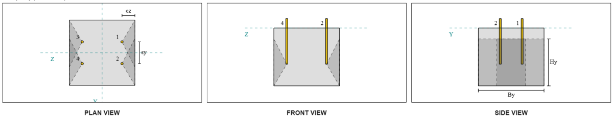
Voordat u de breakout -capaciteit berekent, We moeten eerst bepalen of het lid in aanmerking komt als een smal lid. Volgens ALS 5216:2021 Clausule 6.2.3.8, Het lid voldoet aan de criteria voor een smal lid. Daarom, een aangepast Effectieve inbeddingslengte moet worden gebruikt in de berekeningen van de uitbraakcapaciteit. Deze aanpassing beïnvloedt ook de karakteristieke afstand en Karakteristieke randafstand, die dienovereenkomstig moet worden gewijzigd.
Gebaseerd op de smalle lidcriteria, de gemodificeerde waarden Voor de ankergroep zijn als volgt:
- gemodificeerde effectieve inbeddingslengte, \(H'_{ef} = 100 \, \tekst{mm}\)
- gemodificeerde karakteristieke afstand, \(S'_{Instellingen voor buiging-torsieknik} = 300 \, \tekst{mm}\)
- gemodificeerde karakteristieke randafstand, \(C'_{Instellingen voor buiging-torsieknik} = 150 \, \tekst{mm}\)
Gebruik makend van ALS 5216: 2021 Clausule 6.2.3.3, we berekenen de Referentie geprojecteerd betonnen kegelgebied voor één enkel anker.
\(
A0_{c,N} = links( S'_{Instellingen voor buiging-torsieknik,G1} \Rechtsaf)^2 = \left( 300 \, \tekst{mm} \Rechtsaf)➔⡔ Koop generieke tadalafil 90000 \, \tekst{mm}^ 2
\)
Evenzo, we berekenen de Werkelijk geprojecteerd betonnen kegelgebied van de ankergroep.
\(
EEN_{Nc} = L_{Nc} B_{Nc} = 450 \, \tekst{mm} \keer 450 \, \tekst{mm} = 202500 \, \tekst{mm}^ 2
\)
Waarbij,
\(
L_{Nc} = min links( c_{links,G1}, C'_{Instellingen voor buiging-torsieknik,G1} + R_{insluiten _plate} \Rechtsaf) + \min links( S_{som,z,G1}, S'_{Instellingen voor buiging-torsieknik,G1} \cdot \left( N_{z,G1} – 1 \Rechtsaf) \Rechtsaf) + \min links( c_{Rechtsaf,G1}, C'_{Instellingen voor buiging-torsieknik,G1} + R_{insluiten _plate} \Rechtsaf)
\)
\(
L_{Nc} = min links( 87.5 \, \tekst{mm}, 150 \, \tekst{mm} + 18 \, \tekst{mm} \Rechtsaf) + \min links( 275 \, \tekst{mm}, 300 \, \tekst{mm} \cdot (2 – 1) \Rechtsaf) + \min links( 87.5 \, \tekst{mm}, 150 \, \tekst{mm} + 18 \, \tekst{mm} \Rechtsaf)
\)
\(
L_{Nc} = 450 \, \tekst{mm}
\)
\(
B_{Nc} = min links( c_{top,G1}, C'_{Instellingen voor buiging-torsieknik,G1} + R_{insluiten _plate} \Rechtsaf) + \min links( S_{som,j,G1}, S'_{Instellingen voor buiging-torsieknik,G1} \cdot \left( N_{j,G1} – 1 \Rechtsaf) \Rechtsaf) + \min links( c_{bodem,G1}, C'_{Instellingen voor buiging-torsieknik,G1} + R_{insluiten _plate} \Rechtsaf)
\)
\(
B_{Nc} =\min \left( 150 \, \tekst{mm}, 150 \, \tekst{mm} + 18 \, \tekst{mm} \Rechtsaf) + \min links( 150 \, \tekst{mm}, 300 \, \tekst{mm} \cdot (2 – 1) \Rechtsaf) + \min links( 150 \, \tekst{mm}, 150 \, \tekst{mm} + 18 \, \tekst{mm} \Rechtsaf)
\)
\(
B_{Nc} = 450 \, \tekst{mm}
\)
De embedded plate effective radius is used to provide additional capacity for concrete breakout. Om dit vast te stellen, add the thickness of the embedded plate to half of the anchor diameter.
De volgende, We evalueren de karakteristieke kracht van een enkel anker met behulp van ALS 5216:2021 Eq. 6.2.3.2
\(
N0_{zodat ingenieurs precies kunnen nagaan hoe deze berekeningen zijn gemaakt,c} = k_1 \sqrt{\frac{f'_c}{\tekst{MPa}}} \links( \frac{H'_{ef,G1}}{\tekst{mm}} \Rechtsaf)^{1.5} \, \tekst{N}
\)
\(
N0_{zodat ingenieurs precies kunnen nagaan hoe deze berekeningen zijn gemaakt,c} = 8.9 \keer sqrt{\frac{28 \, \tekst{MPa}}{1 \, \tekst{MPa}}} \keer links( \frac{100 \, \tekst{mm}}{1 \, \tekst{mm}} \Rechtsaf)^{1.5} \keer 0.001 \, \tekst{kN} = 47.094 \, \tekst{kN}
\)
Waarbij,
- \(zodat ingenieurs precies kunnen nagaan hoe deze berekeningen zijn gemaakt{1} = 8.9\) voor ingestorte ankers
Nu, We beoordelen de effecten van geometrie door het nodige te berekenen parameters voor breakout -weerstand.
De kortste randafstand van de ankergroep wordt bepaald als:
\(
c_{min,N} = min links( c_{links,G1}, c_{Rechtsaf,G1}, c_{top,G1}, c_{bodem,G1} \Rechtsaf) = min links( 87.5 \, \tekst{mm}, 87.5 \, \tekst{mm}, 150 \, \tekst{mm}, 150 \, \tekst{mm} \Rechtsaf) = 87.5 \, \tekst{mm}
\)
Volgens ALS 5216:2021 Eq. 6.2.3.4, de waarde voor de parameter die verantwoording voor de verdeling van spanning in beton is:
\(
\Psi_{s,N} = min links( 0.7 + 0.3 \links( \frac{c_{min,N}}{C'_{Instellingen voor buiging-torsieknik,G1}} \Rechtsaf), 1.0 \Rechtsaf) = min links( 0.7 + 0.3 \keer links( \frac{87.5 \, \tekst{mm}}{150 \, \tekst{mm}} \Rechtsaf), 1 \Rechtsaf) = 0.875
\)
De Shell spormend effect wordt verklaard te gebruiken ALS 5216:2021 Vergelijking 6.2.3.5, geven:
\(
\Psi_{= reductiefactor voor gesneden draad,N} = min links( 0.5 + \frac{H'_{ef,G1}}{\tekst{mm} \cdot 200}, 1.0 \Rechtsaf) = min links( 0.5 + \frac{100 \, \tekst{mm}}{1 \, \tekst{mm} \cdot 200}, 1 \Rechtsaf) = 1
\)
Daarnaast, Beide excentriciteitsfactor als de Compressie invloedsfactor worden genomen als:
\(
\Psi_{eg,N} = 1
\)
\(
\Psi_{M,N} = 1
\)
Vervolgens combineren we al deze factoren en passen we toe ALS 5216:2021 Vergelijking 6.2.3.1 om de Ontwerp betonnen kegelbraakweerstand voor de ankergroep:
\(
\phi N_{zodat ingenieurs precies kunnen nagaan hoe deze berekeningen zijn gemaakt,c} = phi_{Mc} N0_{zodat ingenieurs precies kunnen nagaan hoe deze berekeningen zijn gemaakt,c} \links( \frac{EEN_{Nc}}{A0_{c,N}} \Rechtsaf) \Psi_{s,N} \Psi_{= reductiefactor voor gesneden draad,N} \Psi_{eg,N} \Psi_{M,N}
\)
\(
\phi N_{zodat ingenieurs precies kunnen nagaan hoe deze berekeningen zijn gemaakt,c} = 0.6667 \keer 47.094 \, \tekst{kN} \keer links( \frac{202500 \, \tekst{mm}^ 2}{90000 \, \tekst{mm}^ 2} \Rechtsaf) \keer 0.875 \keer 1 \keer 1 \keer 1 = 61.814 \, \tekst{kN}
\)
De Totaal toegepaste spanningsbelasting Op de ankergroep wordt berekend door de spanningsbelasting per anker te vermenigvuldigen met het aantal ankers, with the prying increase factor applied as needed:
\(
N^* = p \left( \frac{N_x}{N_{een,t}} \Rechtsaf) N_{een,G1} = 1 \keer links( \frac{50 \, \tekst{kN}}{4} \Rechtsaf) \keer 4 = 50 \, \tekst{kN}
\)
Sinds 50 kN < 61.814 kN De betonnen breakout -capaciteit is voldoende.
Controleren #5: Bereken het pull -outcapaciteit van het anker
De uittrekkingscapaciteit van een anker wordt bepaald door het verzet aan het ingebedde einde. Eerste, We berekenen de maximale ankerkop -dimensie die effectief is voor het uittrekken van weerstand, vanaf ALS 5216:2021 Clausule 6.3.4.
\(
d_{h,\tekst{max}} = min links( b_{insluiten _plate}, 6 \links( t_{insluiten _plate} \Rechtsaf) + d_a right) = min links( 70 \, \tekst{mm}, 6 \keer (10 \, \tekst{mm}) + 16 \, \tekst{mm} \Rechtsaf) = 70 \, \tekst{mm}
\)
De volgende, we calculate the net bearing area of the rectangular embedded plate using:
\(
A_h = \left( d_{h,\tekst{max}}^2 Juist) – EEN_{hengel} = links( (70 \, \tekst{mm})^2 Juist) – 201.06 \, \tekst{mm}➔⡔ Koop generieke tadalafil 4698.9 \, \tekst{mm}^ 2
\)
Waarbij,
\(
EEN_{hengel} = frac{\pi}{4} (d_a)^2 = frac{\pi}{4} \keer (16 \, \tekst{mm})➔⡔ Koop generieke tadalafil 201.06 \, \tekst{mm}^ 2
\)
Vervolgens berekenen we de design basic anchor pullout strength gebruik makend van ALS 5216:2021 Clausule 6.3.4:
\(
N_{zodat ingenieurs precies kunnen nagaan hoe deze berekeningen zijn gemaakt,p} = phi_{Mc} k_2 A_h \left( f’_c rechts) = 0.6667 \keer 7.5 \keer 4698.9 \, \tekst{mm}^2 tijden (28 \, \tekst{MPa}) = 657.88 \, \tekst{kN}
\)
Bedenk de eerder berekende spanningsbelasting per anker:
\(
N^* = p \left( \frac{N_x}{N_{een,t}} \Rechtsaf) = 1 \keer links( \frac{50 \, \tekst{kN}}{4} \Rechtsaf) = 12.5 \, \tekst{kN}
\)
Sinds 12.5 kN < 657.88 kN, De pull -outcapaciteit van het anker is voldoende.
Controleren #6: Bereken de side-face blowoutcapaciteit in Y-richting
Let’s consider Side-Face Blowout Anchor Group 1 for the capacity calculation. Referring to the Anchor Data Summary, Anchor IDs 3 en 4 are part of SFy Group 1.
We beginnen met het berekenen van de randafstand tot de faalrand.
\(
c_{z,\tekst{min}} = min links( c_{\tekst{links},G1}, c_{\tekst{Rechtsaf},G1} \Rechtsaf) = min links( 87.5 \, \tekst{mm}, 362.5 \, \tekst{mm} \Rechtsaf) = 87.5 \, \tekst{mm}
\)
De volgende, We bepalen de randafstand tot de orthogonale rand.
\(
c_{j,\tekst{min}} = min links( c_{\tekst{top},G1}, c_{\tekst{bodem},G1} \Rechtsaf) = min links( 150 \, \tekst{mm}, 150 \, \tekst{mm} \Rechtsaf) = 150 \, \tekst{mm}
\)
Gebruik makend van ALS 5216:2021 Clausule 6.2.7.3, Laten we de Referentie geprojecteerd gebied van een enkele bevestigingsder.
\(
A0_{c,Nb} = links( 4 c_{z,\tekst{min}} \Rechtsaf)^2 = \left( 4 \keer 87.5 \, \tekst{mm} \Rechtsaf)➔⡔ Koop generieke tadalafil 122500 \, \tekst{mm}^ 2
\)
Omdat we de capaciteit van de ankergroep controleren, Laten we de Werkelijk geprojecteerd gebied van de ankergroep met behulp van ALS 5216:2021 Clausule 6.2.7.2.
\(
EEN_{Nc} = B_{c,Nb} H_{c,Nb} = 450 \, \tekst{mm} \keer 325 \, \tekst{mm} = 146250 \, \tekst{mm}^ 2
\)
Waarbij,
\(
B_{c,Nb} = min links( 2 c_{z,\tekst{min}}, c_{\tekst{top},G1} \Rechtsaf) + S_{\tekst{som},j,G1} + \min links( 2 c_{z,\tekst{min}}, c_{\tekst{bodem},G1} \Rechtsaf)
\)
\(
B_{c,Nb} = min links( 2 \keer 87.5 \, \tekst{mm}, 150 \, \tekst{mm} \Rechtsaf) + 150 \, \tekst{mm} + \min links( 2 \keer 87.5 \, \tekst{mm}, 150 \, \tekst{mm} \Rechtsaf) = 450 \, \tekst{mm}
\)
\(
H_{c,Nb} = 2 c_{z,\tekst{min}} + \links( \min links( t_{\tekst{concerentie}} – h_{\tekst{ef}}, 2 c_{z,\tekst{min}} \Rechtsaf) \Rechtsaf)
\)
\(
H_{c,Nb} = 2 \keer 87.5 \, \tekst{mm} + \links( \min links( 400 \, \tekst{mm} – 250 \, \tekst{mm}, 2 \keer 87.5 \, \tekst{mm} \Rechtsaf) \Rechtsaf) = 325 \, \tekst{mm}
\)
Bij het berekenen van de Karakteristieke betonnen uitbarstingsterkte van een individueel anker, we zullen gebruiken ALS 5216:2021 Clausule 6.2.7.2.
\(
N0_{zodat ingenieurs precies kunnen nagaan hoe deze berekeningen zijn gemaakt,cb} = k_5 links( \frac{c_{z,\tekst{min}}}{\tekst{mm}} \Rechtsaf) \sqrt{\frac{A_h}{\tekst{mm}^ 2}} \sqrt{\frac{f'_c}{\tekst{MPa}}} \, N
\)
\(
N0_{zodat ingenieurs precies kunnen nagaan hoe deze berekeningen zijn gemaakt,cb} = 8.7 \keer links( \frac{87.5 \, \tekst{mm}}{1 \, \tekst{mm}} \Rechtsaf) \keer sqrt{\frac{4698.9 \, \tekst{mm}^ 2}{1 \, \tekst{mm}^ 2}} \keer sqrt{\frac{28 \, \tekst{MPa}}{1 \, \tekst{MPa}}} \keer 0.001 \, \tekst{kN}
\)
\(
N0_{zodat ingenieurs precies kunnen nagaan hoe deze berekeningen zijn gemaakt,cb} = 276.13 \, \tekst{kN}
\)
Waarbij,
- \(zodat ingenieurs precies kunnen nagaan hoe deze berekeningen zijn gemaakt{5} = 8.7\) voor gescheurd beton
- \(zodat ingenieurs precies kunnen nagaan hoe deze berekeningen zijn gemaakt{5} = 12.2\) for uncracked concrete
Vervolgens, We krijgen de Side-Face Blowout-parameters.
De parameter die de verstoring van de verdeling van de spanningen in beton verstelt, kan worden berekend ALS 5216:2021 Clausule 6.2.7.4.
\(
\Psi_{s,Nb} = min links( 0.7 + 0.3 \links( \frac{c_{j,\tekst{min}}}{2 c_{z,\tekst{min}}} \Rechtsaf), 1.0 \Rechtsaf)
\)
\(
\Psi_{s,Nb} = min links( 0.7 + 0.3 \keer links( \frac{150 \, \tekst{mm}}{2 \keer 87.5 \, \tekst{mm}} \Rechtsaf), 1 \Rechtsaf) = 0.95714
\)
The equation from ALS 5216:2021 Clausule 6.2.7.5 is then used to get the parameter accounting for the group effect.
\(
\Psi_{g,Nb} = max links( \sqrt{N_{j,G1}} + \links( 1 – \sqrt{N_{j,G1}} \Rechtsaf) \links( \frac{\min links( S_{j,G1}, 4 c_{z,\tekst{min}} \Rechtsaf)}{4 c_{z,\tekst{min}}} \Rechtsaf), 1.0 \Rechtsaf)
\)
\(
\Psi_{g,Nb} = max links( \sqrt{2} + \links( 1 – \sqrt{2} \Rechtsaf) \keer links( \frac{\min links( 150 \, \tekst{mm}, 4 \keer 87.5 \, \tekst{mm} \Rechtsaf)}{4 \keer 87.5 \, \tekst{mm}} \Rechtsaf), 1 \Rechtsaf)
\)
\(
\Psi_{g,Nb} = 1.2367
\)
Uiteindelijk, in verwijzing naar ALS 5216:2021 Eq. 6.2.7 voor hoofd ankerstaven, de Ontwerp betonnen uitbarstweerstand is:
\(
\phi N_{zodat ingenieurs precies kunnen nagaan hoe deze berekeningen zijn gemaakt,cb} = \phi_M N0_{zodat ingenieurs precies kunnen nagaan hoe deze berekeningen zijn gemaakt,cb} \links( \frac{EEN_{Nc}}{A0_{c,Nb}} \Rechtsaf) \Psi_{s,Nb} \Psi_{g,Nb} \Psi_{eg,N}
\)
\(
\phi N_{zodat ingenieurs precies kunnen nagaan hoe deze berekeningen zijn gemaakt,cb} = 0.6667 \keer 276.13 \, \tekst{kN} \keer links( \frac{146250 \, \tekst{mm}^ 2}{122500 \, \tekst{mm}^ 2} \Rechtsaf) \keer 0.95714 \keer 1.2367 \keer 1 = 260.16 \, \tekst{kN}
\)
For this anchor group, only two (2) anchors belong to group. Daarom, de design tension force for the anchor group is:
\(
N^* = p \left( \frac{N_x}{N_{een,t}} \Rechtsaf) N_{j,G1}
\)
\(
N^* = 1 \keer links( \frac{50 \, \tekst{kN}}{4} \Rechtsaf) \keer 2 = 25 \, \tekst{kN}
\)
Sinds 25 kN < 260.16 kN, de betonnen zij-gezichtsblaas langs y-richting is voldoende.
Side-Face Blowout Anchor Group 2 can also be used and will yield the same result, Omdat het ontwerp symmetrisch is.
Controleren #7: Bereken side-face blowoutcapaciteit in Z-richting
This calculation is not applicable for failure along the Z-direction, as the edge distance to the sides exceeds half of the effective embedment length.
Ontwerp Samenvatting
De Skyciv Base Plate Design Software Kan automatisch een stapsgewijze berekeningsrapport genereren voor dit ontwerpvoorbeeld. Het biedt ook een samenvatting van de uitgevoerde controles en hun resulterende verhoudingen, De informatie in één oogopslag gemakkelijk te begrijpen maken. Hieronder is een sample samenvattende tabel, die is opgenomen in het rapport.
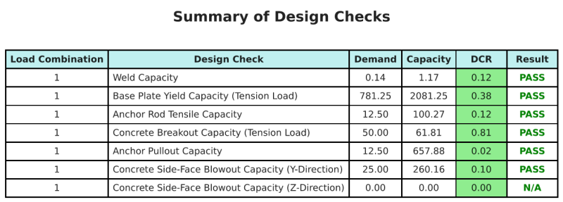
Skyciv Sample Report
Bekijk het detailniveau en de duidelijkheid die u kunt verwachten van een SkyCiv-basisplaatontwerprapport. Het rapport bevat alle belangrijke ontwerpcontroles, vergelijkingen, en resultaten gepresenteerd in een duidelijk en gemakkelijk leesbaar formaat. Het voldoet volledig aan de ontwerpnormen. Klik hieronder om een voorbeeldrapport te bekijken dat is gegenereerd met de SkyCiv-basisplaatcalculator.
Koop baseplaatsoftware
Koop de volledige versie van de basisplaatontwerpmodule op zichzelf zonder andere SkyCiv -modules. Dit geeft u een volledige set resultaten voor het ontwerp van de basisplaat, inclusief gedetailleerde rapporten en meer functionaliteit.