Base plaatontwerp voorbeeld met behulp van AISC 360-22 en ACI 318-19
Probleemverklaring
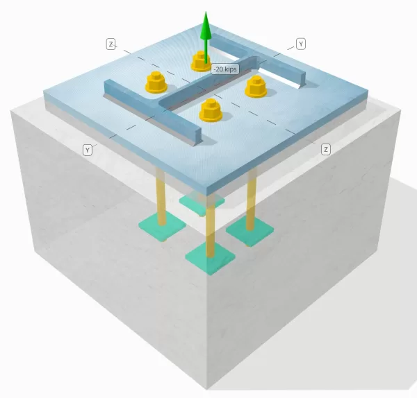
Bepaal of de ontworpen kolom-voetplaatverbinding voldoende is voor een trekbelasting van 20 kipjes.
Gegeven gegevens
Kolom:
Kolomgedeelte: B12x53
Kolomgebied: 15.6 in2
Kolommateriaal: A992
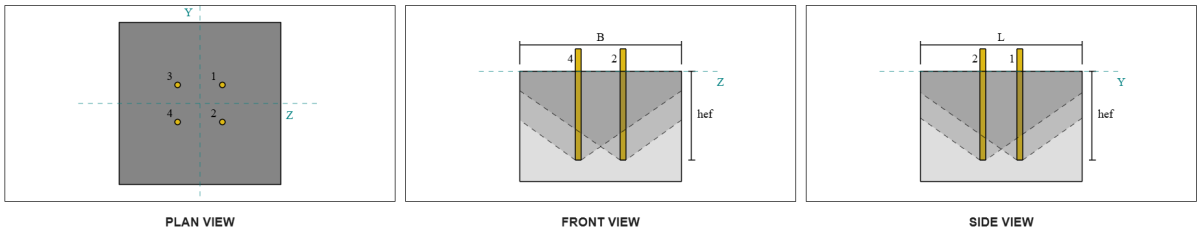
Bodemplaat:
Baseplaat afmetingen: 18 in x 18 in
Basisplaatdikte: 3/4 in
Basisplaatmateriaal: A36
Vocht:
Vochtdikte: 1 in
Beton:
Concrete dimensies: 22 in x 22 in
Betonnen dikte: 15 in
Betonnen materiaal: 4000 psi
Gebarsten of ongescheurd: Gebarsten
Ankers:
Ankerdiameter: 3/4 in
Effectieve inbeddingslengte: 12 in
Ingebedde plaatbreedte: 3 in
Ingebedde plaatdikte: 1/4 in
Offsetafstand van het anker vanaf de voorkant van het kolomlijf: 2.8275 in
Lassen:
Lasgrootte: 1/4 in
Vulmetaalclassificatie: E70XX
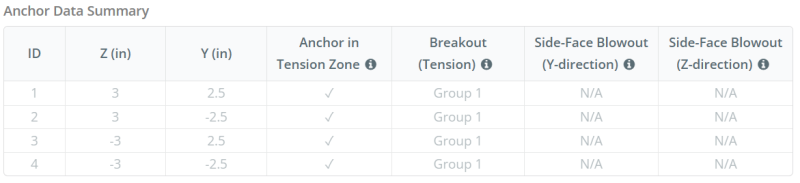
Ankergegevens (van Skyciv Calculator):
Model in SkyCiv Gratis tool
Modelleer vandaag nog het ontwerp van de basisplaat hierboven met onze gratis online tool! Geen aanmelding vereist.
Definities
Pad laden:
Wanneer een grondplaat wordt opgetild (treksterkte) krachten, deze krachten worden overgebracht op de ankerstangen, die op hun beurt buigmomenten in de basisplaat veroorzaken. De buigactie kan worden gevisualiseerd als cantilever buigen die zich voordoen rond de flenzen of het lijf van de kolomsectie, afhankelijk van waar de ankers zijn geplaatst.
In de SkyCiv-software voor het ontwerpen van grondplaten, Alleen ankers in de ankerspanningszone worden als effectief beschouwd bij het weerstaan van opheffing. Deze zone bevat meestal gebieden in de buurt van de kolomflenzen of het web. Ankers buiten deze zone dragen niet bij aan spanningsweerstand en zijn uitgesloten van de Uplift -berekeningen.
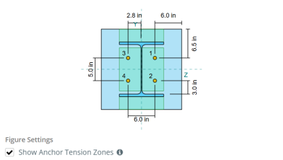
Om het effectieve gebied van de basisplaat te bepalen dat bestand is tegen buigen, een 45-graad spreiding wordt aangenomen vanaf de middellijn van elke ankerstaaf in de richting van het kolomvlak. Deze spreiding definieert de effectieve laslengte en helpt bij het opzetten van de effectieve buigbreedte van de plaat.
De veronderstelling vereenvoudigt de basisplaatanalyse door te benaderen hoe de opheffingskracht zich door de plaat verspreidt.
Ankergroepen:
De SkyCiv-software voor het ontwerpen van grondplaten Bevat een intuïtieve functie die identificeert welke ankers deel uitmaken van een ankergroep om te evalueren beton doorbraak en betonnen zijkante-face uitbarsting mislukkingen.
Een ankergroep bestaat uit meerdere ankers met vergelijkbare effectieve inbeddingsdiepten en afstand, en zijn dichtbij genoeg dat hun geprojecteerde weerstandsgebieden overlappen elkaar. Wanneer ankers zijn gegroepeerd, Hun capaciteiten worden gecombineerd om de totale spanningskracht te weerstaan die op de groep wordt uitgeoefend.
Ankers die niet voldoen aan de groeperingscriteria worden behandeld als enkele ankers. In dit geval, Alleen de spanningskracht op het individuele anker wordt gecontroleerd tegen zijn eigen effectieve weerstandsgebied.
Stapsgewijze berekeningen
Controleren #1: Lascapaciteit berekenen
Beginnen, we moeten de belasting per anker en de effectieve laslengte per anker berekenen. De effectieve laslengte wordt bepaald door de kortste lengte vanaf de laslengte 45° spreiding, beperkt door de werkelijke laslengte en ankerafstand.
Voor deze berekening, ankers worden als een van beide geclassificeerd eind ankers of tussenliggende ankers. Eindankers bevinden zich aan de uiteinden van een rij of kolom ankers, terwijl er tussenliggende ankers tussen zijn geplaatst. De berekeningsmethode verschilt per persoon en is afhankelijk van de kolomgeometrie. In dit voorbeeld, er zijn twee ankers langs het web, en beide zijn geclassificeerd als eindankers.
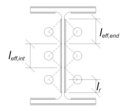
Voor eindankers, de effectieve laslengte wordt beperkt door de beschikbare afstand van de hartlijn van het anker tot de kolomfilet. De spreiding van 45° mag niet verder reiken dan deze grens.
\(
l_r = frac{d_{col} – 2t_f – 2R_{col} – S_(N_{een,⡒🐑⥼ Koop goedkope metoprolol} – 1)}{2} = frac{12.1 \, \tekst{in} – 2 \keer 0.575 \, \tekst{in} – 2 \keer 0.605 \, \tekst{in} – 5 \, \tekst{in} \keer (2 – 1)}{2} = 2.37 \, \tekst{in}
\)
Aan de binnenkant, de effectieve lengte wordt beperkt door de helft van de ankerafstand. De totale effectieve laslengte voor het eindanker is de som van de buiten- en binnenlengte.
\(
l_{eff,einde} = min(Doen, 0.5S_) + \min(Doen, l_r)
\)
\(
l_{eff,einde} = min(2.8275 \, \tekst{in}, 0.5 \keer 5 \, \tekst{in}) + \min(2.8275 \, \tekst{in}, 2.37 \, \tekst{in}) = 4.87 \, \tekst{in}
\)
Voor dit voorbeeld, de uiteindelijke effectieve laslengte voor het webanker wordt de effectieve lengte van het eindanker genomen.
\(
l_{eff} = l_{eff,einde} = 4.87 \, \tekst{in}
\)
De volgende, Laten we de belasting per anker. Voor een gegeven set van vier (4) ankers, de belasting per anker is:
\(
T_{u,anker} = frac{N_x}{N_{een,t}} = frac{20 \, \tekst{kip}}{4} = 5 \, \tekst{kip}
\)
Met behulp van de berekende effectieve laslengte, we kunnen nu de benodigde kracht per lengte-eenheid op de las.
\(
r_u = frac{T_{u,anker}}{l_{eff}} = frac{5 \, \tekst{kip}}{4.87 \, \tekst{in}} = 1.0267 \, \tekst{kip/in}
\)
Nu, we zullen gebruiken AISC 360-22, Hoofdstuk J2.4 om de ontwerpsterkte van de hoeklas te berekenen.
Omdat de uitgeoefende belasting puur axiale spanning is, de hoek \(\theta) wordt genomen als 90°, en de richtingssterktecoëfficiënt kds wordt berekend volgens AISC 360-22 Eq. J2-5.
\(
zodat ingenieurs precies kunnen nagaan hoe deze berekeningen zijn gemaakt{ds} = 1.0 + 0.5(\zonder(\theta))^{1.5} = 1 + 0.5 \keer (\zonder(1.5708))^{1.5} = 1.5
\)
Uiteindelijk, wij zullen toepassen AISC 360-22 Eq. J2-4 Om de ontwerpsterkte van de hoeklas per lengte-eenheid.
\(
\phi r_n = phi 0.6 F_{exx} E_{w,web} zodat ingenieurs precies kunnen nagaan hoe deze berekeningen zijn gemaakt{ds} = 0.75 \keer 0.6 \keer 70 \, \tekst{KSI} \keer 0.177 \, \tekst{in} \keer 1.5 = 8.3633 \, \tekst{kip/in}
\)
Sinds 1.0267 kpi < 8.3633 kpi, De lascapaciteit is voldoende.
Controleren #2: Bereken de buigcapaciteit van de basisplaat als gevolg van spanningsbelasting
Met behulp van thij laadt per anker en de offset-afstand van het midden van het anker tot de voorkant van de kolom (dient als excentriciteit van de belasting), het moment dat op de basisplaat wordt uitgeoefend, kan worden berekend met behulp van a cantilever aanname.
\(
M_u = T_{u,\tekst{anker}} e = 5 \, \tekst{kip} \keer 2.8275 \, \tekst{in} = 14.137 \, \tekst{kip} \cdot tekst{in}
\)
De volgende, met behulp van de berekeningd effectieve laslengte vanafm de vorige controle als de buigbreedte, we kunnen de berekenen is een ontwerpmodule voor het ontwerpen van gespreide funderingen vanaf de bovenbouwbelastingen van de basisplaat gebruiken AISC 360-22, Vergelijking 2-1:
\(
\phi M_n = phi F_{j,\tekst{bp}} Z_{\tekst{eff}} = 0.9 \keer 36 \, \tekst{KSI} \keer 0.68484 \, \tekst{in}^3 = 22.189 \, \tekst{kip} \cdot tekst{in}
\)
Waarbij,
\(
Z_{\tekst{eff}} = frac{l_{\tekst{eff}} (t_{\tekst{bp}})^ 2}{4} = frac{4.87 \, \tekst{in} \keer (0.75 \, \tekst{in})^ 2}{4} = 0.68484 \, \tekst{in}^3
\)
Sinds 14.137 kip-in < 22.189 kip-in, De buigplaten van de basisplaat is voldoende.
Controleren #3: Bereken de trekcapaciteit van de ankerstaaf
Om het trekvermogen van de ankerstang te evalueren, we zullen gebruiken ACI 318-19 Vergelijking 17.6.1.2.
Eerste, We bepalen de gespecificeerde treksterkte van het ankerstaal. Dit is de laagste toegestane waarde ACI 318-19 Clausule 17.6.1.2, met verwijzing naar materiaaleigenschappen in AISC 360-22 Tabel J3.2.
\(
f_{\tekst{uta}} = min links( 0.75 F_{u,\tekst{anc}}, 1.9 F_{j,\tekst{anc}}, 125 \Rechtsaf) = min links( 0.75 \keer 120 \, \tekst{KSI}, 1.9 \keer 92 \, \tekst{KSI}, 125.00 \, \tekst{KSI} \Rechtsaf) = 90 \, \tekst{KSI}
\)
De volgende, we berekenen de effectief dwarsdoorsnedeoppervlak van de ankerstang. Dit is gebaseerd op ACI 318-19 Commentaarclausule R17.6.1.2, wat rekening houdt met de draadgeometrie. Hieruit wordt het aantal draden per inch afgeleid ASME B1.1-2019 Tabel 1.
\(
EEN_{ik weet,N} = frac{\pi}{4} \links( d_a – \frac{0.9743}{n_t} \Rechtsaf)^2 = frac{\pi}{4} \keer links( 0.75 \, \tekst{in} – \frac{0.9743}{10 \, \tekst{in}^{-1}} \Rechtsaf)➔⡔ Koop generieke tadalafil 0.33446 \, \tekst{in}^ 2
\)
Met deze waarden, We passen toe ACI 318-19 Vergelijking 17.6.1.2 om de te berekenen ontwerp treksterkte van de ankerstang.
\(
\phi N_{naar} = phi A_{ik weet,N} f_{\tekst{uta}} = 0.75 \keer 0.33446 \, \tekst{in}^2 tijden 90 \, \tekst{KSI} = 22.576 \, \tekst{kip}
\)
Bedenk de eerder berekende spanningsbelasting per anker:
\(
N_{Doen} = frac{N_x}{N_{een,t}} = frac{20 \, \tekst{kip}}{4} = 5 \, \tekst{kip}
\)
Sinds 5 kip < 22.576 kip, De trekcapaciteit van de ankerkam is voldoende.
Controleren #4: Bereken de betonuitbraakcapaciteit in spanning
Voordat u de breakout -capaciteit berekent, We moeten eerst bepalen of het lid in aanmerking komt als een smal lid. Volgens ACI 318-19 Clausule 17.6.2.1.2, Het lid voldoet aan de criteria voor een smal lid. Daarom, Bij de berekeningen moet gebruik worden gemaakt van een gewijzigde effectieve inbeddingslengte.
Er wordt vastgesteld dat de gemodificeerde effectieve inbeddingslengte, h’ef, van de ankergroep is:
\(
H'_{\tekst{ef}} = 5.667 \, \tekst{in}
\)
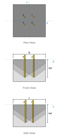
Gebruik makend van ACI 318-19 Clausule 17.6.2, we berekenen de maximaal geprojecteerd betonkegeloppervlak voor één enkel anker, gebaseerd op de gewijzigde effectieve inbeddingslengte.
\(
EEN_{N_{co}} = 9 \links( H'_{ef,G1} \Rechtsaf)➔⡔ Koop generieke tadalafil 9 \keer links( 5.6667 \, \tekst{in} \Rechtsaf)➔⡔ Koop generieke tadalafil 289 \, \tekst{in}^ 2
\)
Evenzo, we gebruiken de gewijzigde effectieve inbeddingslengte om de Werkelijk geprojecteerd betonnen kegelgebied van de ankergroep.
\(
EEN_{N_c} = min links( N_{een,G1} EEN_{N_{co}}, L_{N_c} B_{N_c} \Rechtsaf) = min links( 4 \keer 289 \, \tekst{in}^ 2, 22 \, \tekst{in} \keer 22 \, \tekst{in} \Rechtsaf) = 484 \, \tekst{in}^ 2
\)
Waarbij,
\(
L_{N_c} = min links( c_{\tekst{links},G1}, 1.5 H'_{\tekst{ef},G1} \Rechtsaf)
+ \links( \min links( S_{\tekst{som},z,G1}, 3 H'_{\tekst{ef},G1} \links( N_{z,G1} – 1 \Rechtsaf) \Rechtsaf) \Rechtsaf)
+ \min links( c_{\tekst{Rechtsaf},G1}, 1.5 H'_{\tekst{ef},G1} \Rechtsaf)
\)
\(
L_{N_c} = min links( 8 \, \tekst{in}, 1.5 \keer 5.6667 \, \tekst{in} \Rechtsaf)
+ \links( \min links( 6 \, \tekst{in}, 3 \keer 5.6667 \, \tekst{in} \keer links( 2 – 1 \Rechtsaf) \Rechtsaf) \Rechtsaf)
+ \min links( 8 \, \tekst{in}, 1.5 \keer 5.6667 \, \tekst{in} \Rechtsaf)
\)
\(
L_{N_c} = 22 \, \tekst{in}
\)
\(
B_{N_c} = min links( c_{\tekst{top},G1}, 1.5 H'_{\tekst{ef},G1} \Rechtsaf)
+ \links( \min links( S_{\tekst{som},j,G1}, 3 H'_{\tekst{ef},G1} \links( N_{j,G1} – 1 \Rechtsaf) \Rechtsaf) \Rechtsaf)
+ \min links( c_{\tekst{bodem},G1}, 1.5 H'_{\tekst{ef},G1} \Rechtsaf)
\)
\(
B_{N_c} = min links( 8.5 \, \tekst{in}, 1.5 \keer 5.6667 \, \tekst{in} \Rechtsaf)
+ \links( \min links( 5 \, \tekst{in}, 3 \keer 5.6667 \, \tekst{in} \keer links( 2 – 1 \Rechtsaf) \Rechtsaf) \Rechtsaf)
+ \min links( 8.5 \, \tekst{in}, 1.5 \keer 5.6667 \, \tekst{in} \Rechtsaf)
\)
\(
B_{N_c} = 22 \, \tekst{in}
\)
De volgende, We evalueren de basisbetonuitbreeksterkte van een enkel anker met behulp van ACI 318-19 Clausule 17.6.2.2.1
\(
N_b = k_c lambda_a sqrt{\frac{f'_c}{\tekst{psi}}} \links( \frac{H'_{\tekst{ef},G1}}{\tekst{in}} \Rechtsaf)^{1.5} \, \tekst{lbf}
\)
\(
N_b = 24 \keer 1 \keer sqrt{\frac{4 \, \tekst{KSI}}{0.001 \, \tekst{KSI}}} \keer links( \frac{5.6667 \, \tekst{in}}{1 \, \tekst{in}} \Rechtsaf)^{1.5} \keer 0.001 \, \tekst{kip} = 20.475 \, \tekst{kip}
\)
Waarbij,
- \(zodat ingenieurs precies kunnen nagaan hoe deze berekeningen zijn gemaakt{c} = 24\) voor ingestorte ankers
- \(\lambda = 1.0 \) voor normaal gewicht beton
Nu, we beoordelen de effecten van geometrie door de randeffectfactor als de excentriciteitsfactor.
De kortste randafstand van de ankergroep wordt bepaald als:
\(
c_{een,\tekst{min}} = min links( c_{\tekst{links},G1}, c_{\tekst{Rechtsaf},G1}, c_{\tekst{top},G1}, c_{\tekst{bodem},G1} \Rechtsaf)
= min links( 8 \, \tekst{in}, 8 \, \tekst{in}, 8.5 \, \tekst{in}, 8.5 \, \tekst{in} \Rechtsaf) = 8 \, \tekst{in}
\)
Volgens ACI 318-19 Clausule 17.6.2.4.1, de uitbraak randeffectfactor is:
\(
\Psi_{ed,N} = min links( 1.0, 0.7 + 0.3 \links( \frac{c_{een,\tekst{min}}}{1.5 H'_{\tekst{ef},G1}} \Rechtsaf) \Rechtsaf)
= min links( 1, 0.7 + 0.3 \keer links( \frac{8 \, \tekst{in}}{1.5 \keer 5.6667 \, \tekst{in}} \Rechtsaf) \Rechtsaf) = 0.98235
\)
Omdat de trekbelasting wordt uitgeoefend op het zwaartepunt van de ankergroep, de excentriciteit is nul. Dus, de excentriciteitsfactor, ook uit Clausule 17.6.2.4.1, is:
\(
\Psi_{eg,N} = min links( 1.0, \frac{1}{1 + \frac{2 en N}{3 H'_{\tekst{ef},G1}}} \Rechtsaf)
= min links( 1, \frac{1}{1 + \frac{2 \keer 0}{3 \keer 5.6667 \, \tekst{in}}} \Rechtsaf) = 1
\)
Daarnaast, Beide kraakfactor als de splitsingsfactor worden genomen als:
\(
\Psi_{c,N} = 1
\)
\(
\Psi_{cp,N} = 1
\)
Vervolgens, we combineren al deze factoren en gebruiken ACI 318-19 Eq. 17.6.2.1b om de betonuitbreeksterkte van de ankergroep:
\(
\phi N_{cbg} = phi links( \frac{EEN_{N_c}}{EEN_{N_{co}}} \Rechtsaf) \Psi_{eg,N} \Psi_{ed,N} \Psi_{c,N} \Psi_{cp,N} N_b
\)
\(
\phi N_{cbg} = 0.7 \keer links( \frac{484 \, \tekst{in}^ 2}{289 \, \tekst{in}^ 2} \Rechtsaf) \keer 1 \keer 0.98235 \keer 1 \keer 1 \keer 20.475 \, \tekst{kip} = 23.58 \, \tekst{kip}
\)
De Totaal toegepaste spanningsbelasting op de ankergroep is het product van de individuele ankerbelasting en het aantal ankers:
\(
N_{Doen} = links( \frac{N_x}{N_{een,t}} \Rechtsaf) N_{een,G1} = links( \frac{20 \, \tekst{kip}}{4} \Rechtsaf) \keer 4 = 20 \, \tekst{kip}
\)
Sinds 20 kips < 23.58 kips, De betonnen breakout -capaciteit is voldoende.
Controleren #5: Bereken het pull -outcapaciteit van het anker
Het uittrekvermogen van een anker wordt bepaald door de weerstand aan het ingebedde uiteinde ervan. Beginnen, we berekenen het draagoppervlak van de ingebedde plaat, dat is het netto gebied na het aftrekken van het gebied bezet door de ankerbang.
Voor een rechthoekige inbouwplaat, de lageroppervlak wordt berekend als:
\(
EEN_{brg} = links( \links( b_{insluiten _plate} \Rechtsaf)^2 Juist) – EEN_{hengel} = links( \links( 3 \, \tekst{in} \Rechtsaf)^2 Juist) – 0.44179 \, \tekst{in}➔⡔ Koop generieke tadalafil 8.5582 \, \tekst{in}^ 2
\)
Waarbij,
\(
EEN_{hengel} = frac{\pi}{4} \links( d_a right)^2 = frac{\pi}{4} \keer links( 0.75 \, \tekst{in} \Rechtsaf)➔⡔ Koop generieke tadalafil 0.44179 \, \tekst{in}^ 2
\)
De volgende, We bepalen de basisuittreksterkte van het anker gebruik makend van ACI 318-19 Vergelijking 17.6.3.2.2a.
\(
N_b = 8 EEN_{brg} \links( f’_c rechts) = 8 \keer 8.5582 \, \tekst{in}^2 timesleft( 4 \, \tekst{KSI} \Rechtsaf) = 273.86 \, \tekst{kip}
\)
Vervolgens passen we de juiste weerstandsfactor toe en uittrekscheurfactor:
- Voor gebarsten beton, \(\Psi_{cp} = 1.0\)
- Voor ongebarsten beton, \(\Psi_{cp} = 1.4\)
Deze gebruiken, We berekenen de ontwerp anker uittreksterkte onder spanning per ACI 318-19 Vergelijking 17.6.3.1.
\(
\phi N_{pn} = phi Psi_{c,p} N_b = 0.7 \keer 1 \keer 273.86 \, \tekst{kip} = 191.7 \, \tekst{kip}
\)
Bedenk de eerder berekende spanningsbelasting per anker:
\(
N_{Doen} = frac{N_x}{N_{een,t}} = frac{20 \, \tekst{kip}}{4} = 5 \, \tekst{kip}
\)
Sinds 5 kips < 191.7 kips, De pull -outcapaciteit van het anker is voldoende.
Controleren #6: Bereken de buigcapaciteit van de instortplaat
Dit is een aanvullende controle die wordt uitgevoerd met behulp van de Skyciv Base Plate Design Software om te verifiëren dat de ingebedde plaat voldoende buigvermogen heeft en niet zal meegeven onder de uitgeoefende uittrekbelastingen.
Eerste, wij bepalen de lengte van de vrije (niet ondersteund) uiteinde van de ingebedde plaat, gemeten vanaf de rand van de steun tot aan de voorkant van de staaf.
\(
b’ = frac{b_{insluiten _plate} – d_a}{2} = frac{3 \, \tekst{in} – 0.75 \, \tekst{in}}{2} = 1.125 \, \tekst{in}
\)
De volgende, we berekenen de buigmoment veroorzaakt door de uniforme lagerdruk. Deze druk vertegenwoordigt de kracht die wordt overgedragen van de uittrekactie van het anker op de ingebedde plaat.
\(
m_f = frac{\links( \frac{T_a}{EEN_{brg}} \Rechtsaf) \links( b’ \Rechtsaf)^ 2}{2} = frac{\links( \frac{5 \, \tekst{kip}}{8.5582 \, \tekst{in}^ 2} \Rechtsaf) \keer links( 1.125 \, \tekst{in} \Rechtsaf)^ 2}{2} = 0.36971 \, \tekst{kip}
\)
Uiteindelijk, met behulp van het berekende moment en gegeven materiaaleigenschappen, wij zullen de bepalen minimaal vereiste plaatdikte weerstand bieden buigzame opbrengst.
\(
t_{min} = sqrt{\frac{4 m_v}{\phi F_{j_ep}}} = sqrt{\frac{4 \keer 0.36971 \, \tekst{kip}}{0.9 \keer 36 \, \tekst{KSI}}} = 0.21364 \, \tekst{in}
\)
Denk aan de werkelijke ingebedde plaatdikte:
\(
t_{feitelijk} = t_{insluiten _plate} = 0.25 \, \tekst{in}
\)
Sinds 0.21364 in < 0.25 in, de buigcapaciteit van de ingebedde plaat is voldoende.
Controleren #7: Bereken de side-face blowoutcapaciteit in Y-richting
Deze berekening is niet van toepassing op dit voorbeeld, zoals de voorwaarden gespecificeerd in ACI 318-19 Clausule 17.6.4 worden niet voldaan. Daarom, Er zal geen sprake zijn van een zijwaartse uitbarsting langs de Y-richting.
Controleren #8: Bereken side-face blowoutcapaciteit in Z-richting
Deze berekening is niet van toepassing op dit voorbeeld, zoals de voorwaarden gespecificeerd in ACI 318-19 Clausule 17.6.4 worden niet voldaan. Daarom, Er zal geen sprake zijn van een zijwaartse uitbarsting langs de Z-richting.
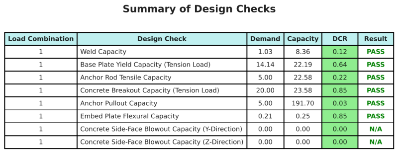
Ontwerp Samenvatting
De Skyciv Base Plate Design Software Kan automatisch een stapsgewijze berekeningsrapport genereren voor dit ontwerpvoorbeeld. Het biedt ook een samenvatting van de uitgevoerde controles en hun resulterende verhoudingen, De informatie in één oogopslag gemakkelijk te begrijpen maken. Hieronder is een sample samenvattende tabel, die is opgenomen in het rapport.
Skyciv Sample Report
Bekijk het detailniveau en de duidelijkheid die u kunt verwachten van een SkyCiv-basisplaatontwerprapport. Het rapport bevat alle belangrijke ontwerpcontroles, vergelijkingen, en resultaten gepresenteerd in een duidelijk en gemakkelijk leesbaar formaat. Het voldoet volledig aan de ontwerpnormen. Klik hieronder om een voorbeeldrapport te bekijken dat is gegenereerd met de SkyCiv-basisplaatcalculator.
Koop baseplaatsoftware
Koop de volledige versie van de basisplaatontwerpmodule op zichzelf zonder andere SkyCiv -modules. Dit geeft u een volledige set resultaten voor het ontwerp van de basisplaat, inclusief gedetailleerde rapporten en meer functionaliteit.