Base plaatontwerp voorbeeld met behulp van EN 1993-1-8:2005, IN 1993-1-1:2005, IN 1992-1-1:2004, and EN 1992-4:2018.
Probleemverklaring
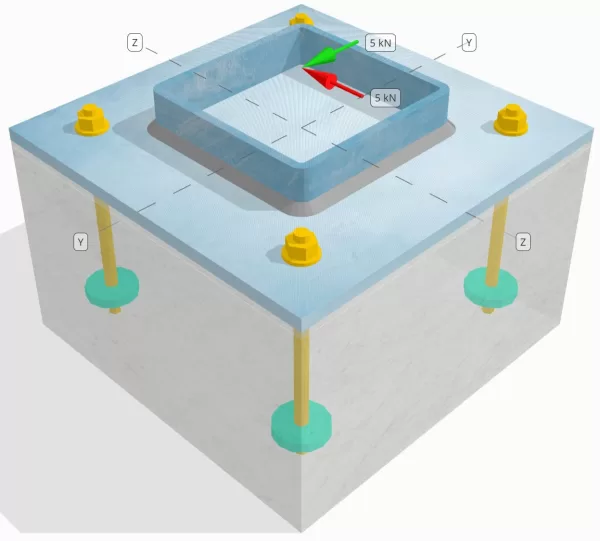
Bepaal of de ontworpen kolom-voetplaatverbinding voldoende is voor een Vy=5-kN en Vz=5-kN schuifbelastingen.
Gegeven gegevens
Kolom:
Kolomgedeelte: SHS 180x180x8
Kolomgebied: 5440 mm2
Kolommateriaal: S235
Bodemplaat:
Baseplaat afmetingen: 350 mm x 350 mm
Basisplaatdikte: 12 mm
Basisplaatmateriaal: S235
Vocht:
Vochtdikte: 6 mm
Voegmateriaal: 30 MPa
Beton:
Concrete dimensies: 350 mm x 350 mm
Betonnen dikte: 350 mm
Betonnen materiaal: C25/30
Gebarsten of ongescheurd: Gebarsten
Ankers:
Ankerdiameter: 12 mm
Effectieve inbeddingslengte: 150 mm
Ingebouwde plaatdiameter: 60 mm
Ingebedde plaatdikte: 10 mm
Ankermateriaal: 8.8
Andere informatie:
- Niet-countersunk ankers.
- Anker met gesneden draden.
- K7-factor voor breuk van ankerstaal: 1.0
- Mate van weerstand van het bevestigingsmiddel: Geen terughoudendheid
Lassen:
Lastype: Hoeklas
Grootte lasbeen: 8mm
Vulmetaalclassificatie: E35
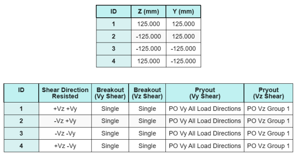
Ankergegevens (van Skyciv Calculator):
Model in SkyCiv Gratis tool
Modelleer vandaag nog het ontwerp van de basisplaat hierboven met onze gratis online tool! Geen aanmelding vereist.
Definities
Pad laden:
De SkyCiv-software voor het ontwerpen van grondplaten volgt IN 1992-4:2018 voor ankerstangontwerp. De op de kolom uitgeoefende schuifbelastingen worden via de lassen overgebracht op de basisplaat en vervolgens via de ankerstangen op het ondersteunende beton. In dit voorbeeld wordt geen rekening gehouden met wrijvings- en afschuifnokken, omdat deze mechanismen niet worden ondersteund in de huidige software.
Ankergroepen:
De software bevat een intuïtieve functie die identificeert welke ankers deel uitmaken van een ankergroep voor evaluatie uitbraak van betonschaar en beton afschuiving mislukkingen.
Een ankergroep wordt gedefinieerd als twee of meer ankers met overlappende geprojecteerde weerstandsgebieden. In dit geval, de ankers werken samen, en hun gecombineerde weerstand wordt vergeleken met de uitgeoefende belasting op de groep.
A enkel anker wordt gedefinieerd als een anker waarvan het geprojecteerde weerstandsgebied met geen enkel ander anker overlapt. In dit geval, het anker handelt alleen, en de uitgeoefende schuifkracht op dat anker wordt rechtstreeks vergeleken met zijn individuele weerstand.
Door dit onderscheid kan de software zowel groepsgedrag als individuele ankerprestaties vastleggen bij het beoordelen van afschuivingsgerelateerde faalwijzen.
Stapsgewijze berekeningen
Controleren #1: Lascapaciteit berekenen
Wij gaan ervan uit dat de Vz De schuifbelasting wordt weerstaan door de boven- en onderlassen, Terwijl de Jij De schuifbelasting wordt uitsluitend weerstaan door de links en rechts laswerk.
Om de lascapaciteit van de boven- en onderlassen, we berekenen eerst hun totale laslengtes.
\(
L_{w,bovenkant&bodem} = 2 \links(b_{col} – 2t_{col} – 2R_{col}\Rechtsaf)
= 2 \keer links(180 \,\tekst{mm} – 2 \keer 8 \,\tekst{mm} – 2 \keer 4 \,\tekst{mm}\Rechtsaf)
= 312 \,\tekst{mm}
\)
De volgende, we berekenen de spanningen in de lasnaden.
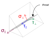
Merk op dat de toegepaste Vz-afschuiving parallel aan de lasas werkt, zonder dat er andere krachten aanwezig zijn. Dit betekent dat de loodrechte spanningen als nul kunnen worden beschouwd, en alleen de schuifspanning in parallelle richting hoeft te worden berekend.
\(
\sigma_{\dader} = frac{N}{(L_{w,bovenkant&bodem})\,asqrt{2}}
= frac{0 \,\tekst{kN}}{(312 \,\tekst{mm}) \keer 5.657 \,\tekst{mm} \keer sqrt{2}}
= 0
\)
\(
\jouw_{\dader} = frac{0}{(L_{w,bovenkant&bodem})\,asqrt{2}}
= frac{0 \,\tekst{kN}}{(312 \,\tekst{mm}) \keer 5.657 \,\tekst{mm} \keer sqrt{2}}
= 0
\)
\(
\jouw_{\parallel} = frac{V_{z}}{(L_{w,bovenkant&bodem})\,een}
= frac{5 \,\tekst{kN}}{(312 \,\tekst{mm}) \keer 5.657 \,\tekst{mm}}
= 2.8329 \,\tekst{MPa}
\)
Gebruik makend van IN 1993-1-8:2005, Eq. 4.1, de ontwerplasspanning wordt verkregen met behulp van de directionele methode.
\(
F_{w,Ed1} = sqrt{ (\sigma_{\dader})^ 2 + 3 \links( (\jouw_{\dader})^ 2 + (\jouw_{\parallel})^2 Juist) }
= sqrt{ (0)^ 2 + 3 \keer links( (0)^ 2 + (2.8329 \,\tekst{MPa})^2 Juist) }
= 4.9067 \,\tekst{MPa}
\)
Daarnaast, de normale ontwerpspanning voor de basismetaalcontrole, per IN 1993-1-8:2005, Eq. 4.1, wordt als nul beschouwd, sinds geen normale spanning is aanwezig.
\(
F_{w,Ed2} = sigma_{\dader} = 0
\)
Nu, laten we beoordelen links en rechts laswerk. Net als bij de boven- en onderlassen, berekenen we eerst de Totale laslengte.
\(
L_{w,links&Rechtsaf} = 2 \links(d_{col} – 2t_{col} – 2R_{col}\Rechtsaf)
= 2 \keer links(180 \,\tekst{mm} – 2 \keer 8 \,\tekst{mm} – 2 \keer 4 \,\tekst{mm}\Rechtsaf)
= 312 \,\tekst{mm}
\)
Vervolgens berekenen we de componenten van de lasspanningen.
\(
\sigma_{\dader} = frac{N}{(L_{w,links&Rechtsaf})\,asqrt{2}}
= frac{0 \,\tekst{kN}}{(312 \,\tekst{mm}) \keer 5.657 \,\tekst{mm} \keer sqrt{2}}
= 0
\)
\(
\jouw_{\dader} = frac{0}{(L_{w,links&Rechtsaf})\,asqrt{2}}
= frac{0 \,\tekst{kN}}{(312 \,\tekst{mm}) \keer 5.657 \,\tekst{mm} \keer sqrt{2}}
= 0
\)
\(
\jouw_{\parallel} = frac{V_y}{(L_{w,links&Rechtsaf})\,een}
= frac{5 \,\tekst{kN}}{(312 \,\tekst{mm}) \keer 5.657 \,\tekst{mm}}
= 2.8329 \,\tekst{MPa}
\)
Gebruik makend van IN 1993-1-8:2005, Eq. 4.1, voor de basismetaalcontrole bepalen wij zowel de ontwerplasspanning als de ontwerpnormaalspanning.
\(
F_{w,Ed1} = sqrt{ \links( \sigma_{\dader} \Rechtsaf)^ 2 + 3 \links( \links( \jouw_{\dader} \Rechtsaf)^ 2 + \links( \jouw_{\parallel} \Rechtsaf)^2 Juist) }
\)
\(
F_{w,Ed1} = sqrt{ \links( 0 \Rechtsaf)^ 2 + 3 \keer links( \links( 0 \Rechtsaf)^ 2 + \links( 2.8329 \,\tekst{MPa} \Rechtsaf)^2 Juist) }
\)
\(
F_{w,Ed1} = 4.9067 \,\tekst{MPa}
\)
De volgende stap is het identificeren van de lasspanning beheersen tussen de boven/onder-lassen en de links/rechts-lassen. Omdat de laslengtes gelijk zijn en de uitgeoefende belastingen dezelfde grootte hebben, de resulterende lasspanningen zijn gelijk.
\(
F_{w,Ed1} = max(F_{w,Ed1}, \, F_{w,Ed1})
= max(4.9067 \,\tekst{MPa}, \, 4.9067 \,\tekst{MPa})
= 4.9067 \,\tekst{MPa}
\)
De basismetaalspanning blijft nul.
\(
F_{w,Ed2} = max(F_{w,Ed2}, \, F_{w,Ed2}) = max(0, \, 0) = 0
\)
Nu, wij berekenen het lasvermogen. Eerste, de weerstand van de hoeklassen wordt berekend. Vervolgens, de weerstand van de basismetaal wordt bepaald. Using EN 1993-1-8:2005, Eq. 4.1, de capaciteiten worden als volgt berekend:
\(
F_{w,Rd1} = frac{f_u}{\beta_w left(\gamma_{M2,weld}\Rechtsaf)}
= frac{360 \,\tekst{MPa}}{0.8 \keer (1.25)}
= 360 \,\tekst{MPa}
\)
\(
F_{w,Rd2} = frac{0.9 f_u}{\gamma_{M2,weld}}
= frac{0.9 \keer 360 \,\tekst{MPa}}{1.25}
= 259.2 \,\tekst{MPa}
\)
Uiteindelijk, we vergelijken de lasspanningen met de lascapaciteiten, en de basismetaalspanningen met de basismetaalcapaciteiten.
Sinds 4.9067 MPa < 360 MPa en 0 MPa < 259.2 MPa, de capaciteit van de lasverbinding is voldoende.
Controleren #2: Bereken het uitbreekvermogen van beton als gevolg van Vy-schuifkracht
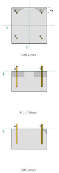
Naar aanleiding van de bepalingen van IN 1992-4:2018, de rand loodrecht op de uitgeoefende belasting wordt beoordeeld op breuk door afschuiving. Alleen de ankers die zich het dichtst bij deze rand bevinden worden als betrokken beschouwd, terwijl van de resterende ankers wordt aangenomen dat ze niet bestand zijn tegen afschuiving.
Deze randankers moeten een betonrandafstand hebben die groter is dan de grootste van 10·hef en 60·d, waar hebben is de inbeddingslengte en d is de ankerdiameter. Als niet aan deze voorwaarde wordt voldaan, de dikte van de bodemplaat moet kleiner zijn dan 0,25·hef.
Als de eisen in IN 1992-4:2018, Clausule 7.2.2.5(1), zijn niet tevreden, de SkyCiv-software kan niet doorgaan met de ontwerpcontroles, en de gebruiker wordt geadviseerd andere relevante normen te raadplegen.
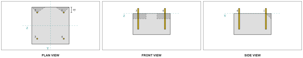
Van de SkyCiv-softwareresultaten, de randankers fungeren als enkele ankers, omdat hun geprojecteerde gebieden elkaar niet overlappen. Voor deze berekening, Anker 1 zal worden overwogen.
Om het deel van de Vy-schuifbelasting te berekenen dat door het anker wordt gedragen 1, de totale Vy-afschuiving wordt verdeeld over de ankers die zich het dichtst bij de rand bevinden. Dit geeft de loodrechte kracht op Anker 1.
\(
V_{\dader} = frac{V_y}{N_{een,s}}
= frac{5 \,\tekst{kN}}{2}
= 2.5 \,\tekst{kN}
\)
Voor de parallelle kracht, Er wordt aangenomen dat alle ankers de belasting in gelijke mate weerstaan. Daarom, de parallelle component van de belasting wordt berekend als:
\(
V_{\parallel} = frac{V_z}{N_{anc}}
= frac{5 \,\tekst{kN}}{4}
= 1.25 \,\tekst{kN}
\)
De totale schuifbelasting op Anker 1 is daarom:
\(
V_{Ed} = sqrt{ \links( V_{\dader} \Rechtsaf)^ 2 + \links( V_{\parallel} \Rechtsaf)^ 2 }
\)
\(
V_{Ed} = sqrt{ \links( 2.5 \,\tekst{kN} \Rechtsaf)^ 2 + \links( 1.25 \,\tekst{kN} \Rechtsaf)^ 2 } = 2.7951 \,\tekst{kN}
\)
Het eerste deel van de capaciteitsberekening is het bepalen van de alfa- en bètafactoren. We gebruiken IN 1992-4:2018, Clausule 7.2.2.5, om de Als afmeting, en Vergelijkingen 7.42 en 7.43 om de factoren te bepalen.
\(
l_f = min(h_{ef}, \, 12d_{anc})
= min(150 \,\tekst{mm}, \, 12 \keer 12 \,\tekst{mm})
= 144 \,\tekst{mm}
\)
\(
\alfa = 0.1 \links(\frac{l_v}{c_{1,s1}}\Rechtsaf)^{0.5}
= 0.1 \keer links(\frac{144 \,\tekst{mm}}{50 \,\tekst{mm}}\Rechtsaf)^{0.5}
= 0.16971
\)
\(
\bèta = 0.1 \links(\frac{d_{anc}}{c_{1,s1}}\Rechtsaf)^{0.2}
= 0.1 \keer links(\frac{12 \,\tekst{mm}}{50 \,\tekst{mm}}\Rechtsaf)^{0.2}
= 0.07517
\)
De volgende stap is het berekenen van de initiële waarde van de karakteristieke weerstand van het bevestigingsmiddel. Gebruik makend van IN 1992-4:2018, Vergelijking 7.41, de waarde is:
\(
V^{0}_{zodat ingenieurs precies kunnen nagaan hoe deze berekeningen zijn gemaakt,c} = k_9 links( \frac{d_{anc}}{\tekst{mm}} \Rechtsaf)^{\alfa}
\links( \frac{l_v}{\tekst{mm}} \Rechtsaf)^{\bèta}
\sqrt{ \frac{f_{zodat ingenieurs precies kunnen nagaan hoe deze berekeningen zijn gemaakt}}{\tekst{MPa}} }
\links( \frac{c_{1,s1}}{\tekst{mm}} \Rechtsaf)^{1.5} N
\)
\(
V^{0}_{zodat ingenieurs precies kunnen nagaan hoe deze berekeningen zijn gemaakt,c} = 1.7 \keer links( \frac{12 \,\tekst{mm}}{1 \,\tekst{mm}} \Rechtsaf)^{0.16971}
\keer links( \frac{144 \,\tekst{mm}}{1 \,\tekst{mm}} \Rechtsaf)^{0.07517}
\keer sqrt{ \frac{20 \,\tekst{MPa}}{1 \,\tekst{MPa}} }
\keer links( \frac{50 \,\tekst{mm}}{1 \,\tekst{mm}} \Rechtsaf)^{1.5}
\keer 0.001 \,\tekst{kN}
\)
\(
V^{0}_{zodat ingenieurs precies kunnen nagaan hoe deze berekeningen zijn gemaakt,c} = 5.954 \,\tekst{kN}
\)
Vervolgens, We berekenen de Referentie geprojecteerd gebied van één enkel anker, als vervolg op IN 1992-4:2018, Vergelijking 7.44.
\(
EEN_{c,V }^{0} = 4.5 \links( c_{1,s1} \Rechtsaf)^ 2
= 4.5 \keer links( 50 \,\tekst{mm} \Rechtsaf)^ 2
= 11250 \,\tekst{mm}^ 2
\)
Daarna, We berekenen de Werkelijk geprojecteerd gebied van Anker 1.
\(
B_{c,V } = min(c_{links,s1}, \, 1.5c_{1,s1}) + \min(c_{Rechtsaf,s1}, \, 1.5c_{1,s1})
\)
\(
B_{c,V } = min(300 \,\tekst{mm}, \, 1.5 \keer 50 \,\tekst{mm}) + \min(50 \,\tekst{mm}, \, 1.5 \keer 50 \,\tekst{mm}) = 125 \,\tekst{mm}
\)
\(
H_{c,V } = min(1.5c_{1,s1}, \, t_{concerentie}) = min(1.5 \keer 50 \,\tekst{mm}, \, 200 \,\tekst{mm}) = 75 \,\tekst{mm}
\)
\(
EEN_{c,V } = H_{c,V } B_{c,V } = 75 \,\tekst{mm} \keer 125 \,\tekst{mm} = 9375 \,\tekst{mm}^ 2
\)
We moeten ook de parameters voor afschuifuitbraak berekenen. We gebruiken IN 1992-4:2018, Vergelijking 7.4, om de factor te vinden die verantwoordelijk is voor de verstoring van de spanningsverdeling, Vergelijking 7.46 voor de factor die verantwoordelijk is voor de dikte van het lid, en Vergelijking 7.48 voor de factor die verantwoordelijk is voor de invloed van een schuifbelasting hellend naar de rand. Deze worden als volgt berekend:
\(
\Psi_{s,V } = min links( 0.7 + 0.3 \links( \frac{c_{2,s1}}{1.5c_{1,s1}} \Rechtsaf), \, 1.0 \Rechtsaf)
= min links( 0.7 + 0.3 \keer links( \frac{50 \,\tekst{mm}}{1.5 \keer 50 \,\tekst{mm}} \Rechtsaf), \, 1 \Rechtsaf)
= 0.9
\)
\(
\Psi_{h,V } = max links( \links( \frac{1.5c_{1,s1}}{t_{concerentie}} \Rechtsaf)^{0.5}, \, 1 \Rechtsaf)
= max links( \links( \frac{1.5 \keer 50 \,\tekst{mm}}{200 \,\tekst{mm}} \Rechtsaf)^{0.5}, \, 1 \Rechtsaf)
= 1
\)
\(
\alfa_{V } = tan^{-1} \links( \frac{V_{\parallel}}{V_{\dader}} \Rechtsaf)
= tan^{-1} \links( \frac{1.25 \,\tekst{kN}}{2.5 \,\tekst{kN}} \Rechtsaf)
= 0.46365 \,\tekst{rad}
\)
\(
\Psi_{\alfa,V } = max links(
\sqrt{ \frac{1}{(\omdat(\alfa_{V }))^ 2 + \links( 0.5 \, (\zonder(\alfa_{V })) \Rechtsaf)^ 2 } }, \, 1 \Rechtsaf)
\)
\(
\Psi_{\alfa,V } = max links(
\sqrt{ \frac{1}{(\omdat(0.46365 \,\tekst{rad}))^ 2 + \links( 0.5 \maal zonde(0.46365 \,\tekst{rad}) \Rechtsaf)^ 2 } }, \, 1 \Rechtsaf)
\)
\(
\Psi_{\alfa,V } = 1.0847
\)
Een belangrijke opmerking bij het bepalen van de alfafactor is ervoor te zorgen dat de loodrechte en parallelle schuifkrachten correct worden geïdentificeerd.
Uiteindelijk, We berekenen de uitbraakweerstand van het enkele anker dat wordt gebruikt IN 1992-4:2018, Vergelijking 7.1.
\(
V_{zodat ingenieurs precies kunnen nagaan hoe deze berekeningen zijn gemaakt,c} = V^0_{zodat ingenieurs precies kunnen nagaan hoe deze berekeningen zijn gemaakt,c} \links(\frac{EEN_{c,V }}{EEN^0_{c,V }}\Rechtsaf)
\Psi_{s,V } \Psi_{h,V } \Psi_{eg,V } \Psi_{\alfa,V } \Psi_{= reductiefactor voor gesneden draad,V }
\)
\(
V_{zodat ingenieurs precies kunnen nagaan hoe deze berekeningen zijn gemaakt,c} = 5.954 \,\tekst{kN} \keer links(\frac{9375 \,\tekst{mm}^ 2}{11250 \,\tekst{mm}^ 2}\Rechtsaf)
\keer 0.9 \keer 1 \keer 1 \keer 1.0847 \keer 1
= 4.8435 \,\tekst{kN}
\)
Toepassing van de partiële factor, de ontwerpweerstand is 3.23 kN.
\(
V_{Rd,c} = frac{V_{zodat ingenieurs precies kunnen nagaan hoe deze berekeningen zijn gemaakt,c}}{\gamma_{Mc}}
= frac{4.8435 \,\tekst{kN}}{1.5}
= 3.229 \,\tekst{kN}
\)
Sinds 2.7951 kN < 3.229 kN, het afschuifvermogen voor Vy-afschuiving is voldoende.
Controleren #3: Bereken het uitbreekvermogen van beton als gevolg van Vz-schuifkracht
Dezelfde aanpak wordt gebruikt om de capaciteit op de rand loodrecht op de Vz-afschuiving te bepalen.
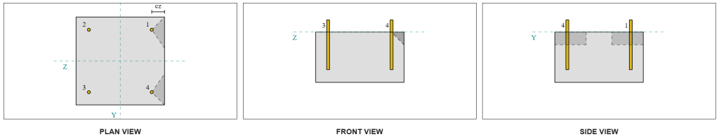
Vanwege het symmetrische ontwerp, de ankers die bestand zijn tegen Vz-schuifkracht worden ook geïdentificeerd als enkele ankers. Laten we eens overwegen Anker 1 nogmaals voor de berekeningen.
Om de te berekenen loodrechte belasting op Anker 1, we delen de Vz-schuifkracht alleen door het totale aantal ankers dat zich het dichtst bij de rand bevindt. Om de te berekenen parallelle belasting op Anker 1, we delen de Vy-afschuiving door het totale aantal ankers.
\(
V_{\dader} = frac{V_{z}}{N_{een,s}}
= frac{5 \,\tekst{kN}}{2}
= 2.5 \,\tekst{kN}
\)
\(
V_{\parallel} = frac{V_{j}}{N_{anc}}
= frac{5 \,\tekst{kN}}{4}
= 1.25 \,\tekst{kN}
\)
\(
V_{Ed} = sqrt{ \links( V_{\dader} \Rechtsaf)^ 2 + \links( V_{\parallel} \Rechtsaf)^ 2 }
\)
\(
V_{Ed} = sqrt{ \links( 2.5 \,\tekst{kN} \Rechtsaf)^ 2 + \links( 1.25 \,\tekst{kN} \Rechtsaf)^ 2 }
= 2.7951 \,\tekst{kN}
\)
Met behulp van een vergelijkbare aanpak als Check #2, het resultaat uitbraakweerstand voor de rand loodrecht op Vz is de afschuiving:
\(
V_{Rd,c} = frac{V_{zodat ingenieurs precies kunnen nagaan hoe deze berekeningen zijn gemaakt,c}}{\gamma_{Mc}}
= frac{4.8435 \,\tekst{kN}}{1.5}
= 3.229 \,\tekst{kN}
\)
Sinds 2.7951 kN < 3.229 kN, het afschuifvermogen voor Vz-afschuiving is voldoende.
Controleren #4: Bereken het uitbreekvermogen van het beton
De berekening voor de weerstand tegen uitbreken houdt in het bepalen van de nominale capaciteit van de ankers tegen spanningsuitbraak. De referentie voor het uitbreekvermogen van spanning is IN 1992-4:2018, Clausule 7.2.1.4. Een gedetailleerde bespreking van het uitbreken van spanning wordt al behandeld in de SkyCiv-ontwerpvoorbeeld met trekbelasting en zal in dit ontwerpvoorbeeld niet worden herhaald.
Van de SkyCiv-softwareberekeningen, de nominale capaciteit van de sectie voor het uitbreken van spanning is 44.61 kN.
We gebruiken dan IN 1992-4:2018, Vergelijking 7.39a, om de ontwerpkarakteristieke weerstand te verkrijgen. Gebruik makend van k8 = 2, de capaciteit is 59.48 kN.
\(
V_{Rd,cp} = frac{k_8 N_{cbg}}{\gamma_C}
= frac{2 \keer 44.608 \,\tekst{kN}}{1.5}
= 59.478 \,\tekst{kN}
\)
In de afschuifcontrole, alle ankers zijn effectief in het weerstaan van de volledige schuifbelasting. Van de afbeelding gegenereerd door de SkyCiv-software, alle projecties van faalkegels overlappen elkaar, waardoor de ankers fungeren als een ankergroep.
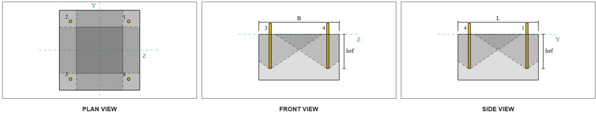
Daarom, de vereiste weerstand van de ankergroep is de totale resulterende schuifbelasting van 7.07 kN.
\(
V_{res} = sqrt{(V_y)^ 2 + (V_z)^ 2}
= sqrt{(5 \,\tekst{kN})^ 2 + (5 \,\tekst{kN})^ 2}
= 7.0711 \,\tekst{kN}
\)
\(
V_{Ed} = links(\frac{V_{res}}{N_{anc}}\Rechtsaf) N_{een,G1}
= links(\frac{7.0711 \,\tekst{kN}}{4}\Rechtsaf) \keer 4
= 7.0711 \,\tekst{kN}
\)
Sinds 7.0711 kN < 59.478 kN, de afschuifkracht is voldoende.
Controleren #5: Bereken de afschuifcapaciteit van de ankerstang
De berekening van het afschuifvermogen van de ankerstang is afhankelijk van het feit of de afschuifbelasting wordt uitgeoefend met een momentarm. Om dit vast te stellen, wij verwijzen naar IN 1992-4:2018, Clausule 6.2.2.3, waar de dikte en het materiaal van de voeg, het aantal bevestigingsmiddelen in het ontwerp, de afstand tussen de bevestigingsmiddelen, en andere factoren worden gecontroleerd.
De Skyciv Base Plate Design Software voert alle noodzakelijke controles uit om vast te stellen of de schuifbelasting werkt met of zonder hefboomarm. Voor dit ontwerpvoorbeeld, er wordt bepaald dat de schuifbelasting gelijk is niet toegepast met een hefboomarm. Daarom, we gebruiken IN 1992-4:2018, Clausule 7.2.2.3.1, voor de capaciteitsvergelijkingen.
We beginnen met het berekenen van de karakteristieke weerstand van het stalen bevestigingsmiddel IN 1992-4:2018, Vergelijking 7.34.
\(
V^0_{zodat ingenieurs precies kunnen nagaan hoe deze berekeningen zijn gemaakt,s} = k_6 A_s f_{u,anc}
= 0.5 \keer 113.1 \,\tekst{mm}^2 tijden 800 \,\tekst{MPa}
= 45.239 \,\tekst{kN}
\)
De volgende, we passen de factor toe voor de ductiliteit van het enkele anker of de ankergroep, nemen k7 = 1.
\(
V_{zodat ingenieurs precies kunnen nagaan hoe deze berekeningen zijn gemaakt,s} = k_7 V^{0}_{zodat ingenieurs precies kunnen nagaan hoe deze berekeningen zijn gemaakt,s}
= 1 \keer 45.239 \,\tekst{kN}
= 45.239 \,\tekst{kN}
\)
Wij verkrijgen dan de gedeeltelijke factor voor het falen van staalafschuiving gebruik makend van IN 1992-4:2018, Tafel 4.1. Voor een anker met 8.8 materiaal, de resulterende partiële factor is:
\(
\gamma_{zodat ingenieurs precies kunnen nagaan hoe deze berekeningen zijn gemaakt,schuintrekken}
= max links( 1.0 \links( \frac{F_{u,anc}}{F_{j,anc}} \Rechtsaf), \, 1.25 \Rechtsaf)
= max links( 1 \[object Window]{800 \,\tekst{MPa}}{640 \,\tekst{MPa}}, \, 1.25 \Rechtsaf)
= 1.25
\)
Deze factor toepassen op de karakteristieke weerstand, de ontwerpweerstand is 36.19 kN.
\(
V_{Rd,s} = frac{V_{zodat ingenieurs precies kunnen nagaan hoe deze berekeningen zijn gemaakt,s}}{\gamma_{zodat ingenieurs precies kunnen nagaan hoe deze berekeningen zijn gemaakt,schuintrekken}}
= frac{45.239 \,\tekst{kN}}{1.25}
= 36.191 \,\tekst{kN}
\)
De vereiste schuifweerstand per ankerstaaf is de resulterende schuifbelasting gedeeld door het totaal aantal ankerstaven, die berekent 1.77 kN.
\(
V_{Ed} = frac{\sqrt{ (V_y)^ 2 + (V_z)^ 2 }}{N_{anc}}
\)
\(
V_{Ed} = frac{\sqrt{ (5 \,\tekst{kN})^ 2 + (5 \,\tekst{kN})^ 2 }}{4}
= 1.7678 \,\tekst{kN}
\)
Sinds 1.7678 kN < 36.191 kN, de afschuifcapaciteit van het ankerstaafstaal is voldoende.
Controleren #6: Bereken het draagvermogen van de basisplaat
de obstructie onder het dakoppervlak Controle van de weerstand van het lager van de basisplaat werd geïntroduceerd in een latere update van de software. Alstublieft zie deze link voor een voorbeeldberekening en gedetailleerde uitleg.
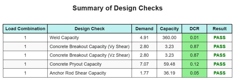
Ontwerp Samenvatting
De Skyciv Base Plate Design Software Kan automatisch een stapsgewijze berekeningsrapport genereren voor dit ontwerpvoorbeeld. Het biedt ook een samenvatting van de uitgevoerde controles en hun resulterende verhoudingen, De informatie in één oogopslag gemakkelijk te begrijpen maken. Hieronder is een sample samenvattende tabel, die is opgenomen in het rapport.
Skyciv Sample Report
Bekijk het detailniveau en de duidelijkheid die u kunt verwachten van een SkyCiv-basisplaatontwerprapport. Het rapport bevat alle belangrijke ontwerpcontroles, vergelijkingen, en resultaten gepresenteerd in een duidelijk en gemakkelijk leesbaar formaat. Het voldoet volledig aan de ontwerpnormen. Klik hieronder om een voorbeeldrapport te bekijken dat is gegenereerd met de SkyCiv-basisplaatcalculator.
Koop baseplaatsoftware
Koop de volledige versie van de basisplaatontwerpmodule op zichzelf zonder andere SkyCiv -modules. Dit geeft u een volledige set resultaten voor het ontwerp van de basisplaat, inclusief gedetailleerde rapporten en meer functionaliteit.