Ontwerpvoorbeeld van basisplaat met CSA S16:19 en CSA A23.3:19
Probleemverklaring
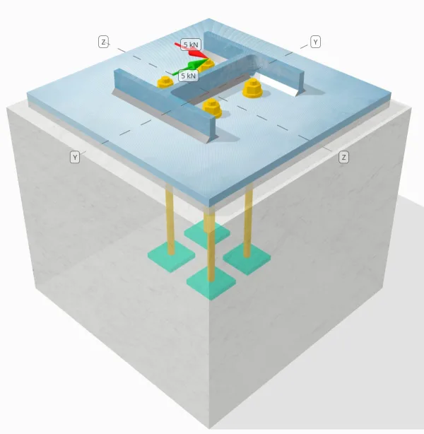
Bepaal of de ontworpen kolom-voetplaatverbinding voldoende is voor een Vy=5-kN en Vz=5-kN schuifbelastingen.
Gegeven gegevens
Kolom:
Kolomgedeelte: HP200x54
Kolomgebied: 6840.0 mm2
Kolommateriaal: 350W
Bodemplaat:
Baseplaat afmetingen: 400 mm x 400 mm
Basisplaatdikte: 13 mm
Basisplaatmateriaal: 300W
Vocht:
Voegdikte: 13 mm
Beton:
Concrete dimensies: 450 mm x 450 mm
Betonnen dikte: 380 mm
Betonnen materiaal: 20.68 MPa
Gebarsten of ongescheurd: Gebarsten
Ankers:
Ankerdiameter: 12.7 mm
Effectieve inbeddingslengte: 300 mm
Dikte van de plaatring: 0 mm
Aansluiting plaatwasmachine: Nee
Lassen:
Lasgrootte: 8 mm
Vulmetaalclassificatie: E43XX
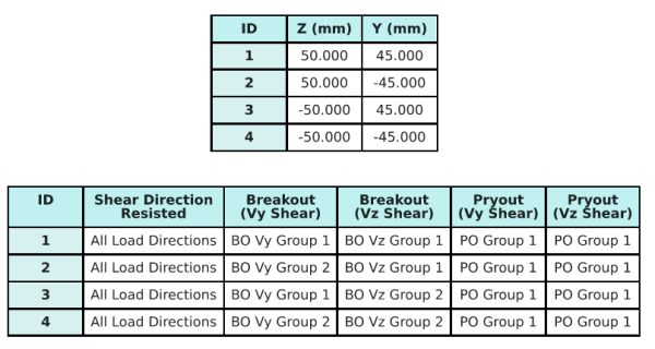
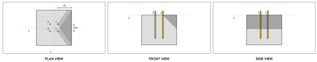
Ankergegevens (van Skyciv Calculator):
Model in SkyCiv Gratis tool
Modelleer vandaag nog het ontwerp van de basisplaat hierboven met onze gratis online tool! Geen aanmelding vereist.
Definities
Pad laden:
Het ontwerp volgt de CSA A23.3:2019 normen en de aanbevelingen van AISC-ontwerpgids 1, 3RD -editie. De op de kolom uitgeoefende schuifbelastingen worden via de lassen overgebracht op de basisplaat, en vervolgens naar het ondersteunende beton via de anker staven. In dit voorbeeld wordt geen rekening gehouden met wrijvings- en afschuifnokken, omdat deze mechanismen niet worden ondersteund in de huidige software.
Standaard, de de uitgeoefende schuifbelasting wordt over alle ankers verdeeld, hetzij door het gebruik van gelaste plaatringen, hetzij door andere technische middelen. De door elk anker gedragen belasting wordt bepaald met behulp van de drie (3) gevallen vermeld in CSA A23.3:2019 Clausule D.7.2.1 en figuur D.13. Elk anker brengt vervolgens de belasting over op het ondersteunende beton eronder. De belastingverdeling in overeenstemming met deze referenties wordt ook gebruikt bij het controleren van de schuifsterkte van het ankerstaal om continuïteit in de aannames van de belastingoverdracht te garanderen.
Als een alternatief, de software maakt een vereenvoudigde en conservatievere aanname mogelijk, waar de de volledige schuifbelasting wordt alleen toegewezen aan de ankers die zich het dichtst bij de belaste rand bevinden. In dit geval, de controle van de afschuifcapaciteit wordt alleen op deze randankers uitgevoerd, ervoor te zorgen dat potentieel afschuiffalen conservatief wordt aangepakt.
Ankergroepen:
De SkyCiv-software voor het ontwerpen van grondplaten Bevat een intuïtieve functie die identificeert welke ankers deel uitmaken van een ankergroep om te evalueren uitbraak van betonschaar en beton afschuiving mislukkingen.
Een ankergroep wordt gedefinieerd als twee of meer ankers met overlappende geprojecteerde weerstandsgebieden. In dit geval, de ankers werken samen, en hun gecombineerde weerstand wordt vergeleken met de uitgeoefende belasting op de groep.
A enkel anker wordt gedefinieerd als een anker waarvan het geprojecteerde weerstandsgebied met geen enkel ander anker overlapt. In dit geval, het anker handelt alleen, en de uitgeoefende schuifkracht op dat anker wordt rechtstreeks vergeleken met zijn individuele weerstand.
Door dit onderscheid kan de software zowel groepsgedrag als individuele ankerprestaties vastleggen bij het beoordelen van afschuivingsgerelateerde faalwijzen.
Stapsgewijze berekeningen
Controleren #1: Lascapaciteit berekenen
De eerste stap is het berekenen van de Totale laslengte beschikbaar om weerstand te bieden tegen afschuiving. De totale laslengte, Lweld, wordt verkregen door de lassen aan alle zijden op te tellen.
\( L_{lassen} = 2b_f + 2(d_{col} – 2t_f – 2R_{col}) + 2(b_f – t_w – 2R_{col}) \)
\( L_{lassen} = 2 \maal 207,tekst{mm} + 2 \keer (204,\tekst{mm} – 2 \maal 11,3,tekst{mm} – 2 \maal 9,7,tekst{mm}) + 2 \keer (207,\tekst{mm} – 11.3,\tekst{mm} – 2 \maal 9,7,tekst{mm}) = 1090.6,tekst{mm} \)
Gebruik deze laslengte, de uitgeoefende schuifkrachten in de y- en z-richtingen worden verdeeld om het gemiddelde te bepalen afschuifkracht per lengte-eenheid in elke richting:
\( v_{fy} = frac{V_y}{L_{lassen}} = frac{5,\tekst{kN}}{1090.6,\tekst{mm}} = 0,0045846,tekst{kN / mm} \)
\( v_{fz} = frac{V_z}{L_{lassen}} = frac{5,\tekst{kN}}{1090.6,\tekst{mm}} = 0,0045846,tekst{kN / mm} \)
De daaruit voortvloeiende vraag naar afschuifkracht per lengte-eenheid wordt vervolgens bepaald met behulp van de wortel uit de som van de kwadraten (SRSS) methode.
\( v_f = sqrt{\links((v_{fy})^2rechts) + \links((v_{fz})^2rechts)} \)
\( v_f = sqrt{\links((0.0045846,\tekst{kN / mm})^2rechts) + \links((0.0045846,\tekst{kN / mm})^2rechts)} = 0,0064836,tekst{kN / mm} \)
De volgende, de lascapaciteit wordt berekend met behulp van CSA S16:19 Clausule 13.13.2.2, waarbij de richtingssterktecoëfficiënt wordt genomen als kds=1,0 om conservatief te zijn. De lascapaciteit voor een las van 8 mm op zowel de flenzen als het lijf is:
\( v_r = 0,67phi t_{w,de berekeningen die hier worden gepresenteerd, zullen het toegestane spanningsontwerp gebruiken}X_u = 0.67 \keer 0.67 \maal 5.657,tekst{mm} \maal 430,tekst{MPa} = 1,092,tekst{kN / mm} \)
\( v_r = 0,67phi t_{w,web}X_u = 0.67 \keer 0.67 \maal 5.657,tekst{mm} \maal 430,tekst{MPa} = 1,092,tekst{kN / mm} \)
Het regeren capaciteit voor hoeklassen is:
\( v_{r,filet} = min(v_r, v_i) = min(1.092\,\tekst{kN / mm}, 1.092\,\tekst{kN / mm}) = 1,092,tekst{kN / mm} \)
Voor deze lasverbinding, de elektrodesterkte overtreft niet de sterkten van het basismetaal. Daarom, de basismetaalcontrole is niet bepalend en hoeft niet te worden uitgevoerd.
Sinds 0.0064 kN / mm < 1.092 kN / mm, de meegerekende lascapaciteit is voldoende.
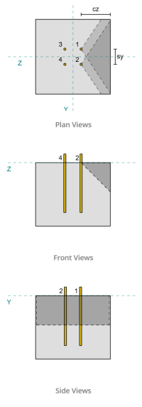
Controleren #2: Bereken het uitbreekvermogen van beton als gevolg van Vy-schuifkracht
Capaciteit loodrechte rand:
Gebruik de ca1-waarden van elk anker om de faalkegels te projecteren, de software heeft vastgesteld dat de faalkegels van deze ankers elkaar overlappen. Daarom, we kunnen ze behandelen als een ankergroep. Verwijzend naar CSA A23.3:19 Afb. D.13, omdat s<ca1 , we gebruiken Geval 3 om de weerstand van de ankergroep tegen afschuifuitbraak te bepalen. Verder, de steun werd bepaald niet smal lid zijn, dus de ca1-afstand wordt direct en zonder wijziging gebruikt.
Geval 3:
De totale kracht waarmee rekening moet worden gehouden voor Case 3 is de volledige schuifkracht langs de Vy-richting. Deze schuifkracht wordt alleen op de voorste ankers uitgeoefend.
\( V_{faverp,geval3} = V_y = 5,tekst{kN} \)
Om de capaciteit van de ankergroep te berekenen, we gebruiken CSA A23.3:19 Artikel D.7.2. De maximaal geprojecteerd gebied voor een enkel anker wordt berekend met behulp van Vergelijking D.34 met de werkelijke cadimensie.
\( EEN_{Vco} = 4.5(c_{a1, g1})➔⡔ Koop generieke tadalafil 4.5 \keer (180\,\tekst{mm})^2 = 145800,tekst{mm}^ 2 \)
Om het werkelijke geprojecteerde gebied van de ankergroep te verkrijgen, We bepalen eerst de breedte van het bezwijkoppervlak:
\( B_{Vc} = min(c_{\tekst{links},G1}, 1.5c_{a1, g1}) + (\min(S_{\tekst{som},X,G1}, 3c_{a1, g1}(N_{X,G1} – 1))) + \min(c_{\tekst{Rechtsaf},G1}, 1.5c_{a1, g1}) \)
\( B_{Vc} = min(175\,\tekst{mm}, 1.5 \maal 180,tekst{mm}) + (\min(100\,\tekst{mm}, 3 \maal 180,tekst{mm} \keer (2-1))) + \min(175\,\tekst{mm}, 1.5 \maal 180,tekst{mm}) \)
\( B_{Vc} = 450,tekst{mm} \)
De hoogte van het bezwijkoppervlak is:
\( H_{Vc} = min(1.5c_{a1, g1}, t_{\tekst{concerentie}}) = min(1.5 \maal 180,tekst{mm}, 380\,\tekst{mm}) = 270,tekst{mm} \)
Dit geeft de totale oppervlakte net zo:
\( EEN_{Vc} = B_{Vc}.H_{Vc} = 450,tekst{mm} \maal 270,tekst{mm} = 121500,tekst{mm}^ 2 \)
We gebruiken dan CSA A23.3:19 Vergelijkingen D.35 en D.36 om de fundamentele uitbreeksterkte van een enkel anker te verkrijgen.
\( V_{br1} = 0,58links(\frac{\min(de, 8d_a)}{d_a}\Rechtsaf)^{0.2}\sqrt{\frac{d_a}{mm}}\philambda_asqrt{\frac{f'_c}{MPa}}\links(\frac{c_{a1, g1}}{mm}\Rechtsaf)^{1.5}R(N) \)
\( V_{br1} = 0.58 \keer links(\frac{\min(300\,\tekst{mm}, 8 \maal 12,7,tekst{mm})}{12.7\,\tekst{mm}}\Rechtsaf)^{0.2} \keer sqrt{\frac{12.7\,\tekst{mm}}{1\,\tekst{mm}}} \keer 0.65 \keer 1 \keer sqrt{\frac{20.68\,\tekst{MPa}}{1\,\tekst{MPa}}} \keer links(\frac{180\,\tekst{mm}}{1\,\tekst{mm}}\Rechtsaf)^{1.5} \keer 1 \maal 0,001,tekst{kN} \)
\( V_{br1} = 22.364,tekst{kN} \)
\( V_{br2} = 3,75lambda_aphisqrt{\frac{f'_c}{MPa}}\links(\frac{c_{a1, g1}}{mm}\Rechtsaf)^{1.5}R(N) \)
\( V_{br2} = 3.75 \keer 1 \keer 0.65 \keer sqrt{\frac{20.68\,\tekst{MPa}}{1\,\tekst{MPa}}} \keer links(\frac{180\,\tekst{mm}}{1\,\tekst{mm}}\Rechtsaf)^{1.5} \keer 1 \maal 0,001,tekst{kN} = 26.769,tekst{kN} \)
De regerende capaciteit tussen de twee voorwaarden is:
\( V_{br} = min(V_{\tekst{br1}}, V_{\tekst{br2}}) = min(22.364\,\tekst{kN}, 26.769\,\tekst{kN}) = 22.364,tekst{kN} \)
De volgende, we berekenen de excentriciteitsfactor, randeffectfactor, en diktefactor gebruiken CSA A23.3:19 Artikelen D.7.2.5, D.7.2.6, en D.7.2.8.
De excentriciteitsfactor is:
\( \Psi_{eg,V } = minlinks(1.0, \frac{1}{1 + \frac{2en N}{3c_{a1, g1}}}\Rechtsaf) = minlinks(1, \frac{1}{1 + \frac{2\keer0}{3\times180,tekst{mm}}}\Rechtsaf) = 1 \)
De randeffectfactor is:
\( \Psi_{ed,V } = minlinks(1.0, 0.7 + 0.3\links(\frac{c_{a2,g1}}{1.5c_{a1, g1}}\Rechtsaf)\Rechtsaf) = minlinks(1, 0.7 + 0.3 \keer links(\frac{175\,\tekst{mm}}{1.5 \maal 180,tekst{mm}}\Rechtsaf)\Rechtsaf) = 0.89444 \)
De diktefactor is:
\( \Psi_{h,V } = maxlinks(\sqrt{\frac{1.5c_{a1, g1}}{t_{\tekst{concerentie}}}}, 1.0\Rechtsaf) = maxlinks(\sqrt{\frac{1.5 \maal 180,tekst{mm}}{380\,\tekst{mm}}}, 1\Rechtsaf) = 1 \)
Uiteindelijk, de uitbreeksterkte van de ankergroep, berekend met CSA A23.3:19 Artikel D.7.2.1, is:
\( V_{cbgperp} = links(\frac{EEN_{Vc}}{EEN_{Vco}}\Rechtsaf)\Psi_{eg,V }\Psi_{ed,V }\Psi_{c,V }\Psi_{h,V }V_{br} \)
\( V_{cbgperp} = links(\frac{121500\,\tekst{mm}^ 2}{145800\,\tekst{mm}^ 2}\Rechtsaf) \keer 1 \keer 0.89444 \keer 1 \keer 1 \maal 22.364,tekst{kN} = 16.669,tekst{kN} \)
De berekende capaciteit voor Vy-afschuiving in de loodrechte richting is 16.669 kN.
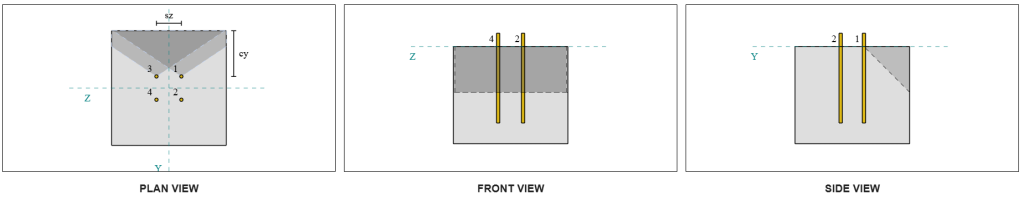
Capaciteit parallelle randen:
Mislukking langs de rand evenwijdig aan de last is in dit scenario ook mogelijk, dus moet het betonuitbreekvermogen voor de parallelle rand worden bepaald. De betrokken ankers zijn verschillend vanwege de nieuwe projectie van de faalkegel. Gebaseerd op onderstaande figuur, de projecties van faalkegels overlappen elkaar; daarom, de ankers worden opnieuw behandeld als een ankergroep.
Geval 3:
De te gebruiken Case is nog steeds Geval 3 sinds s<ca1. Daarom, de belasting die door deze ankergroep wordt opgenomen is de volledige Vy-schuifbelasting.
\( V_{faverp,geval3} = V_y = 5,tekst{kN} \)
Wij volgen dan dezelfde stappen wat betreft de loodrechte capaciteit.
Het faaloppervlak voor een individueel anker is:
\( EEN_{Vco} = 4.5(c_{a1, g1})➔⡔ Koop generieke tadalafil 4.5 \keer (175\,\tekst{mm})^2 = 137810,tekst{mm}^ 2 \)
De feitelijke storingsoppervlak van de ankergroep is:
\( B_{Vc} = min(c_{\tekst{bodem},G1}, 1.5c_{a1, g1}) + (\min(S_{\tekst{som},j,G1}, 3c_{a1, g1}(N_{j,G1} – 1))) + \min(c_{\tekst{top},G1}, 1.5c_{a1, g1}) \)
\( B_{Vc} = min(180\,\tekst{mm}, 1.5 \maal 175,tekst{mm}) + (\min(90\,\tekst{mm}, 3 \maal 175,tekst{mm} \keer (2-1))) + \min(180\,\tekst{mm}, 1.5 \maal 175,tekst{mm}) \)
\( B_{Vc} = 450,tekst{mm} \)
\( H_{Vc} = min(1.5c_{a1, g1}, t_{\tekst{concerentie}}) = min(1.5 \maal 175,tekst{mm}, 380\,\tekst{mm}) = 262,5,tekst{mm} \)
\( EEN_{Vc} = B_{Vc}H_{Vc} = 450,tekst{mm} \maal 262,5,tekst{mm} = 118130,tekst{mm}^ 2 \)
Evenzo, de basis uitbraak van een enkel anker sterke punten worden als volgt berekend:
\( V_{br1} = 0,58links(\frac{\min(de, 8d_a)}{d_a}\Rechtsaf)^{0.2}\sqrt{\frac{d_a}{mm}}\philambda_asqrt{\frac{f'_c}{MPa}}\links(\frac{c_{a1, g1}}{mm}\Rechtsaf)^{1.5}R(N) \)
\( V_{br1} = 0.58 \keer links(\frac{\min(300\,\tekst{mm}, 8 \maal 12,7,tekst{mm})}{12.7\,\tekst{mm}}\Rechtsaf)^{0.2} \keer sqrt{\frac{12.7\,\tekst{mm}}{1\,\tekst{mm}}} \keer 0.65 \keer 1 \keer sqrt{\frac{20.68\,\tekst{MPa}}{1\,\tekst{MPa}}} \keer links(\frac{175\,\tekst{mm}}{1\,\tekst{mm}}\Rechtsaf)^{1.5} \keer 1 \maal 0,001,tekst{kN} \)
\( V_{br1} = 21.438,tekst{kN} \)
\( V_{br2} = 3,75lambda_aphisqrt{\frac{f'_c}{MPa}}\links(\frac{c_{a1, g1}}{mm}\Rechtsaf)^{1.5}R(N) \)
\( V_{br2} = 3.75 \keer 1 \keer 0.65 \keer sqrt{\frac{20.68\,\tekst{MPa}}{1\,\tekst{MPa}}} \keer links(\frac{175\,\tekst{mm}}{1\,\tekst{mm}}\Rechtsaf)^{1.5} \keer 1 \maal 0,001,tekst{kN} = 25.661,tekst{kN} \)
De bestuurskracht is:
\( V_{br} = min(V_{\tekst{br1}}, V_{\tekst{br2}}) = min(21.438\,\tekst{kN}, 25.661\,\tekst{kN}) = 21.438,tekst{kN} \)
Vervolgens berekenen we de excentriciteitsfactor en diktefactor:
\( \Psi_{eg,V } = minlinks(1.0, \frac{1}{1 + \frac{2en N}{3c_{a1, g1}}}\Rechtsaf) = minlinks(1, \frac{1}{1 + \frac{2\keer0}{3\times175,tekst{mm}}}\Rechtsaf) = 1 \)
\( \Psi_{h,V } = maxlinks(\sqrt{\frac{1.5c_{a1, g1}}{t_{\tekst{concerentie}}}}, 1.0\Rechtsaf) = maxlinks(\sqrt{\frac{1.5 \maal 175,tekst{mm}}{380\,\tekst{mm}}}, 1\Rechtsaf) = 1 \)
Voor de breakout edge-effectfactor, wij nemen het als 1.0 voor CSA A23.3:19 Artikel D.7.2.1c. Daarnaast, de waarde van het uitbreekvermogen voor de loodrechte rand wordt genomen als tweemaal de berekende waarde met behulp van vergelijking D.33 (voor een ankergroep).
De meegerekend uitbreekvermogen van de ankergroep is:
\( V_{cbgrparallel} = 2links(\frac{EEN_{Vc}}{EEN_{Vco}}\Rechtsaf)\Psi_{eg,V }\Psi_{ed,V }\Psi_{c,V }\Psi_{h,V }V_{br} \)
\( V_{cbgrparallel} = 2 \keer links(\frac{118130\,\tekst{mm}^ 2}{137810\,\tekst{mm}^ 2}\Rechtsaf) \keer 1 \keer 1 \keer 1 \keer 1 \maal 21.438,tekst{kN} = 36.752,tekst{kN} \)
- Voor de loodrechte rand mislukking, sinds 5 kN < 16.7 kN, het uitbreekvermogen van beton afschuiving is voldoende.
- Voor de parallelle rand mislukking, sinds 5 kN < 36.8 kN, het uitbreekvermogen van beton afschuiving is voldoende.
Bereken het uitbreekvermogen van beton als gevolg van Vz-schuifkracht
De basisplaat wordt ook onderworpen aan Vz-afschuiving, dus de mislukking randen loodrecht en evenwijdig aan de Vz-afschuiving moet worden gecontroleerd. Met dezelfde aanpak, de loodrechte en parallelle capaciteiten worden berekend als 16.6 kN en 37.3 kN, respectievelijk.
Loodrechte rand:
Parallelle rand:
Deze capaciteiten worden vervolgens vergeleken met de benodigde sterke punten.
- Voor de loodrechte rand mislukking, sinds 5 kN < 16.6 kN, het meegerekende uitbreekvermogen van beton afschuiving is voldoende.
- Voor de parallelle randfout, sinds 5 kN < 37.3 kN, het meegerekende uitbreekvermogen van beton afschuiving is voldoende.
Controleren #4: Bereken het uitbreekvermogen van het beton
De betonnen kegel voor mislukte uitbraak is dezelfde kegel die wordt gebruikt in de controle op trekuitbraak. Om het losbreekvermogen te berekenen, de nominale treksterkte van de afzonderlijke ankers of ankergroep moet eerst worden bepaald. Gedetailleerde berekeningen voor de trekuitbraakcontrole worden al behandeld in de SkyCiv-ontwerpvoorbeelden voor trekbelasting en wordt hier niet herhaald.
Het is belangrijk op te merken dat de bepaling van de ankergroep voor afschuifuitbraak anders is dan die voor afschuifuitbraak. Er moet nog gecontroleerd worden of de ankers in het ontwerp aanwezig zijn fungeren als een groep of als enkele ankers. De classificatie van de ondersteuning als een smal gedeelte moeten ook worden geverifieerd en moeten dezelfde voorwaarden volgen die worden gebruikt voor het uitbreken van spanning.
Volgens de SkyCiv-software, de nominale trekuitbreeksterkte van de ankergroep is 60.207 kN. Met een losbreekfactor van 2.0, de ingecalculeerde loshaalcapaciteit is:
\( V_{cpgr} = reductiefactor voor gesneden draad{cp}N_{cbr} = 2 \maal 60.207,tekst{kN} = 120.41,tekst{kN} \)
De vereiste sterkte is de resulterend van de toegepaste schuifbelastingen. Omdat alle ankers tot één groep behoren, de totale resulterende afschuiving wordt aan de groep toegewezen.
\( V_{fa} = sqrt{((V_y)^ 2) + ((V_z)^ 2)} = sqrt{((5\,\tekst{kN})^ 2) + ((5\,\tekst{kN})^ 2)} = 7.0711,tekst{kN} \)
\( V_{fa} = links(\frac{V_{fa}}{n_a}\Rechtsaf)N_{een,G1} = links(\frac{7.0711\,\tekst{kN}}{4}\Rechtsaf) \keer 4 = 7.0711,tekst{kN} \)
Sinds 7.07 kN < 120.4 kN, de meegerekende loshaalcapaciteit is voldoende.
Controleren #5: Bereken de afschuifcapaciteit van de ankerstang
Bedenk dat in dit ontwerpvoorbeeld, De schuifkracht wordt over alle ankers verdeeld. De totale schuifbelasting per anker is daarom de resultante van zijn aandeel in de Vy-belasting en zijn aandeel in de Vz-belasting. Wij houden ook rekening met de regerende zaak gebruikt bij de controles op afschuiving.
Voor Vy-afschuiving, Geval 3 regeert.
\( V_{fa,j} = frac{V_y}{N_{z,G1}} = frac{5\,\tekst{kN}}{2} = 2,5,tekst{kN} \)
Evenzo, voor Vz-afschuiving, Geval 3 regeert.
\( V_{fa,z} = frac{V_z}{N_{j,G1}} = frac{5\,\tekst{kN}}{2} = 2,5,tekst{kN} \)
Dit geeft de schuifkracht op de ankerstang net zo:
\( V_{fa} = sqrt{((V_{fa,j})^ 2) + ((V_{fa,z})^ 2)} = sqrt{((2.5\,\tekst{kN})^ 2) + ((2.5\,\tekst{kN})^ 2)} = 3,5355,tekst{kN} \)
In dit ontwerpvoorbeeld, voegmiddel aanwezig. Daarom, de ankerstang ervaart ook buigen door excentrische afschuiving. Om hier rekening mee te houden, we kunnen de reductiefactor voor grout volgens CSA A23.3:19 Artikel D.7.1.3 of controleer de interactie tussen afschuiving en buiging met behulp van CSA S16:19 Clausule 13.12.1.4.
Voor deze berekening, we hebben ervoor gekozen om gebruik te maken van de 0.8 afname factor uit CSA A23.3. Om individueel technisch oordeel mogelijk te maken, de SkyCiv-basisplaatsoftware biedt de mogelijkheid om deze reductiefactor uit te schakelen en in plaats daarvan de interactiecontrole tussen schuifkracht en buiging te gebruiken. Deze functie kan worden verkend met behulp van de Basisplaat gratis gereedschap.
CSA A23.3 Afschuifcapaciteit van ankerstangen:
Eerste, we berekenen de afschuifcapaciteit van de ankerstang met behulp van CSA A23.3. De minimale trekspanning van de ankerstang is:
\( f_{uta} = min(F_{u _anc}, 1.9F_{de eerste}, 860) = min(400\,\tekst{MPa}, 1.9 \maal 248,2,tekst{MPa}, 860.00\,\tekst{MPa}) = 400,tekst{MPa} \)
De rekening gehouden met de afschuifcapaciteit van de ankerstang, berekend met CSA A23.3:19 Vergelijking D.31 en clausule D.7.1.3, is:
\( V_{sar,een23} = 0,8A_{ik weet,V }\phi_s0.6f_{uta}R = 0.8 \maal 92,tekst{mm}^2 tijden 0.85 \keer 0.6 \maal 400,tekst{MPa} \keer 0.75 = 11.258,tekst{kN} \)
Merk op dat de 0.8 Hier wordt een reductiefactor toegepast vanwege de aanwezigheid van grout. Deze verminderde afschuifcapaciteit is verantwoordelijk voor de extra buiging van de ankerstaaf.
CSA S16 Afschuifcapaciteit ankerstang:
Voor de CSA S16-capaciteit, alleen de afschuifcapaciteit is gecontroleerdd, aangezien met de buiging als gevolg van excentrische afschuiving al rekening is gehouden in de CSA A23.3-controle.
De berekende afschuifcapaciteit wordt berekend met behulp van CSA S16:19 Clausule 25.3.3.3.
\( V_{r,s16} = 0,7phi_m 0,6n A_{sr} F_{u _anc} = 0.7 \keer 0.67 \keer 0.6 \keer 1 \maal 126,68,tekst{mm}^2 maal 400,tekst{MPa} = 14.255,tekst{kN} \)
Om ervoor te zorgen dat beide methoden worden overwogen, het bestuursvermogen wordt als de kleinste van de twee waarden genomen, dat is 11.258 kN.
Sinds 3.54 kN < 11.258 kN, het meegerekende afschuifvermogen van de ankerstang is voldoende.
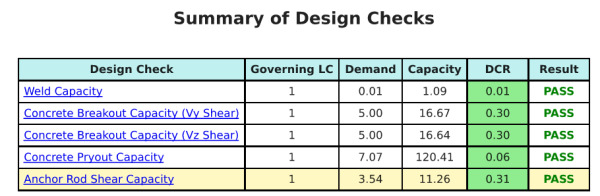
Ontwerp Samenvatting
De Skyciv Base Plate Design Software Kan automatisch een stapsgewijze berekeningsrapport genereren voor dit ontwerpvoorbeeld. Het biedt ook een samenvatting van de uitgevoerde controles en hun resulterende verhoudingen, De informatie in één oogopslag gemakkelijk te begrijpen maken. Hieronder is een sample samenvattende tabel, die is opgenomen in het rapport.
Skyciv Sample Report
Bekijk het detailniveau en de duidelijkheid die u kunt verwachten van een SkyCiv-basisplaatontwerprapport. Het rapport bevat alle belangrijke ontwerpcontroles, vergelijkingen, en resultaten gepresenteerd in een duidelijk en gemakkelijk leesbaar formaat. Het voldoet volledig aan de ontwerpnormen. Klik hieronder om een voorbeeldrapport te bekijken dat is gegenereerd met de SkyCiv-basisplaatcalculator.
Koop baseplaatsoftware
Koop de volledige versie van de basisplaatontwerpmodule op zichzelf zonder andere SkyCiv -modules. Dit geeft u een volledige set resultaten voor het ontwerp van de basisplaat, inclusief gedetailleerde rapporten en meer functionaliteit.