Base plaatontwerp voorbeeld met behulp van EN 1993-1-8-2005, IN 1993-1-1-2005 and EN 1992-1-1-2004
Probleemverklaring
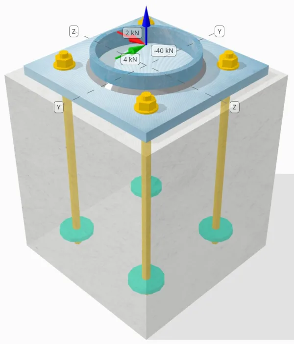
Bepaal of de ontworpen kolom-voetplaatverbinding voldoende is voor een 50-kN trekbelasting, 4-kN Vy schuifbelasting, en 2-kN Vz schuifbelasting.
Gegeven gegevens
Kolom:
Kolomgedeelte: CHS193.7×10
Kolomgebied: 5770.0 mm²
Kolommateriaal: S460
Bodemplaat:
Baseplaat afmetingen: 300mm x 300 mm
Basisplaatdikte: 18mm
Basisplaatmateriaal: S235
Vocht:
Vochtdikte: 0 mm
Beton:
Concrete dimensies: 350x 350 mm
Betonnen dikte: 400 mm
Betonnen materiaal: C35/45
Gebarsten of ongescheurd: Gebarsten
Ankers:
Ankerdiameter: 16 mm
Effectieve inbeddingslengte: 350 mm
Ingebouwde plaatdiameter: 70 mm
Ingebedde plaatdikte: 10 mm
Ankermateriaal: 4.8
Lassen:
Lastype: Filet
Lasgrootte: 7mm
Vulmetaalclassificatie: E42
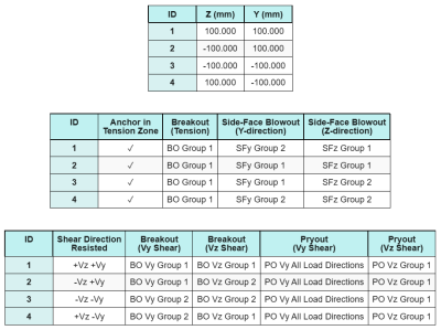
Ankergegevens (van Skyciv Calculator):
Model in SkyCiv Gratis tool
Modelleer vandaag nog het ontwerp van de basisplaat hierboven met onze gratis online tool! Geen aanmelding vereist.
Opmerkingen
Het doel van dit ontwerpvoorbeeld is om de stapsgewijze berekeningen te demonstreren voor capaciteitscontroles met gelijktijdige schuif- en axiale belastingen. Een aantal van de vereiste controles zijn al besproken in de voorgaande ontwerpvoorbeelden. Raadpleeg de links in elke sectie.
Stapsgewijze berekeningen
Controleren #1: Lascapaciteit berekenen
De volledige trekbelasting wordt tegengewerkt door de gehele lasgedeelte, Terwijl de schuifbelastingcomponenten worden slechts over een deel van de totale laslengte verdeeld. Dit gedeelte wordt bepaald door het projecteren van a 90° sector van het midden van de kolom naar de omtrek ervan. Daarom, enkel en alleen helft van de totale omtrek is ontworpen om weerstand te bieden aan de schuifbelasting.
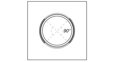
Wij berekenen eerst de Totale laslengte als de gedeelte van de las binnen de projectie van 90°.
\(L_{lassen,vol} = pi d_{col} = pi tijden 193.7\ \tekst{mm} = 608.53\ \tekst{mm}\)
\(L_{lassen} = frac{\pi d_{col}}{2} = frac{\pi \times 193.7\ \tekst{mm}}{2} = 304.26\ \tekst{mm}\)
De volgende, we berekenen de resulterende schuifbelasting.
\(V_r = \sqrt{(V_y)^ 2 + (V_z)^ 2} = sqrt{(4\ \tekst{kN})^ 2 + (2\ \tekst{kN})^ 2} = 4.4721\ \tekst{kN}\)
Vervolgens berekenen wij de normaal en schuifspanningen, rekening houdend met de veronderstelde belastingsverdeling.
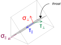
\( \sigma_{\dader} = frac{N_x}{L_{lassen,vol}\,a\,\sqrt{2}} = frac{40\ \tekst{kN}}{608.53\ \tekst{mm} \keer 4.95\ \tekst{mm} \keer sqrt{2}} = 9.39\ \tekst{MPa} \)
\( \jouw_{\dader} = frac{N_x}{L_{lassen,vol}\,a\,\sqrt{2}} = frac{40\ \tekst{kN}}{608.53\ \tekst{mm} \keer 4.95\ \tekst{mm} \keer sqrt{2}} = 9.39\ \tekst{MPa} \)
\( \jouw_{\parallel} = frac{V_r}{L_{lassen}\,een} = frac{4.4721\ \tekst{kN}}{304.26\ \tekst{mm} \keer 4.95\ \tekst{mm}} = 2.9693\ \tekst{MPa} \)
Daarna, we berekenen de gecombineerde spanningen gebruik makend van IN 1993-1-8:2005 Eq. (4.1).
\(F_{w,Ed1} = sqrt{(\sigma_{\dader})^ 2 + 3\groot((\jouw_{\dader})^ 2 + (\jouw_{\parallel})^2\big)}\)
\(F_{w,Ed1} = sqrt{(9.39\ \tekst{MPa})^ 2 + 3\groot((9.39\ \tekst{MPa})^ 2 + (2.9693\ \tekst{MPa})^2\big)}\)
\(F_{w,Ed1} = 19.471\ \tekst{MPa}\)
Tegelijkertijd, We bepalen de spanning op het basismetaal met behulp van dezelfde vergelijking.
\(F_{w,Ed2} = sigma_{\dader} = 9.39\ \tekst{MPa}\)
De volgende, we berekenen de lascapaciteit. Wij bepalen eerst de ultieme treksterkte (het programma wijst lengte toe) van de zwakker materiaal, en dan gebruiken IN 1993-1-8:2005 Eq. (4.1) om de te verkrijgen weerstand tegen hoeklassen en basismetaal weerstand.
\(f_u = \min\!\links(F_{u,\tekst{col}},\ f_{u,\tekst{bp}},\ f_{u,w}\Rechtsaf) = \min\!\links(550\ \tekst{MPa},\ 360\ \tekst{MPa},\ 500\ \tekst{MPa}\Rechtsaf) = 360\ \tekst{MPa}\)
\(F_{w,Rd1} = frac{f_u}{\beta_w\,(\gamma_{M2,\text{lassen}})} = frac{360\ \tekst{MPa}}{0.8 \keer (1.25)} = 360\ \tekst{MPa}\)
\(F_{w,Rd2} = frac{0.9\,f_u}{\gamma_{M2,\text{lassen}}} = frac{0.9 \keer 360\ \tekst{MPa}}{1.25} = 259.2\ \tekst{MPa}\)
Sinds 19.471 MPa < 360 MPa, De lascapaciteit is voldoende.
Controleren #2: Bereken de buigcapaciteit van de basisplaat als gevolg van spanningsbelasting
Een ontwerpvoorbeeld voor het buigvloeivermogen van de basisplaat wordt al besproken in het ontwerpvoorbeeld voor spanning van de basisplaat. Voor de stapsgewijze berekening verwijzen wij u naar deze link.
Controleren #3: Bereken de betonuitbraakcapaciteit in spanning
Een ontwerpvoorbeeld voor het vermogen van het beton bij uitbreken als gevolg van trekbelasting wordt al besproken in het Ontwerpvoorbeeld voetplaat voor spanning. Voor de stapsgewijze berekening verwijzen wij u naar deze link.
Controleren #4: Bereken het pull -outcapaciteit van het anker
Een ontwerpvoorbeeld voor de uittrekcapaciteit van het anker wordt al besproken in het ontwerpvoorbeeld voor spanning van de basisplaat. Voor de stapsgewijze berekening verwijzen wij u naar deze link.
Controleren #5: Bereken de side-face blowoutcapaciteit in Y-richting
Een ontwerpvoorbeeld voor het uitblaasvermogen aan de zijkant in Y-richting wordt al besproken in het ontwerpvoorbeeld voor de basisplaat voor spanning. Voor de stapsgewijze berekening verwijzen wij u naar deze link.
Controleren #6: Bereken side-face blowoutcapaciteit in Z-richting
Een ontwerpvoorbeeld voor het uitblaasvermogen aan de zijkant in Z-richting wordt al besproken in het ontwerpvoorbeeld voor spanning van de basisplaat. Voor de stapsgewijze berekening verwijzen wij u naar deze link.
Controleren #7: Bereken het draagvermogen van de basisplaat bij ankergaten (Vy afschuiving)
Een ontwerpvoorbeeld voor het draagvermogen van de basisplaat in de ankergaten voor Vy-afschuiving wordt al besproken in het ontwerpvoorbeeld van de basisplaat voor compressie en afschuiving. Voor de stapsgewijze berekening verwijzen wij u naar deze link.
Controleren #8: Bereken het draagvermogen van de basisplaat bij ankergaten (Vz-afschuiving)
Een ontwerpvoorbeeld voor het draagvermogen van de basisplaat in de ankergaten voor Vz-afschuiving wordt al besproken in het ontwerpvoorbeeld van de basisplaat voor compressie en afschuiving. Voor de stapsgewijze berekening verwijzen wij u naar deze link.
Controleren #9: Bereken het uitbreekvermogen van beton (Vy afschuiving)
Een ontwerpvoorbeeld voor de betoncapaciteit bij uitbraakbreuk als gevolg van Vy-schuifkracht wordt al besproken in het Basisplaatontwerpvoorbeeld voor schuifkracht. Voor de stapsgewijze berekening verwijzen wij u naar deze link.
Controleren #10: Bereken het uitbreekvermogen van beton (Vz-afschuiving)
Een ontwerpvoorbeeld voor de betoncapaciteit bij uitbraakbreuk als gevolg van Vz-schuifkracht wordt al besproken in het Basisplaatontwerpvoorbeeld voor schuifkracht. Voor de stapsgewijze berekening verwijzen wij u naar deze link.
Controleren #11: Bereken de loshaalcapaciteit
Een ontwerpvoorbeeld voor de uitbreekcapaciteit van beton wordt al besproken in het ontwerpvoorbeeld van de basisplaat voor afschuiving. Voor de stapsgewijze berekening verwijzen wij u naar deze link.
Controleren #12: Bereken de afschuifcapaciteit van de ankerstang
Het effect van de spanning belasting Bij deze controle wordt rekening gehouden met de capaciteit van de ankerstang schuifkracht werkt met een hefboomarm. Echter, in dit voorbeeld, de schaar werkt zonder hefboomarm. Daarom, de interactie tussen schuif- en trekspanningen op de ankerstaaf zal afzonderlijk worden geëvalueerd in de interactiecontrole.
Voor de stapsgewijze berekening van het schuifvermogen zonder hefboomarm, Raadpleeg deze link.
De SkyCiv Base Plate Design-software kan alle noodzakelijke controles uitvoeren om te bepalen of de schuifbelasting met of zonder hefboomarm werkt. Jij kan probeer de gratis tool uit vandaag.
Controleren #13: Bereken de interactiecontrole van het ankerstaal
We gebruiken IN 1992-4:2018 Tafel 7.3 Eq. (7.54) om de interactie tussen schuif- en trekspanningen op de ankerstang. Door zowel de trekspanning en capaciteit als de schuifspanning en capaciteit in de vergelijking in te vullen, het resultaat interactie waarde is:
\(IK_{int} = links(\frac{N_{Ed}}{N_{Rd,s}}\Rechtsaf)^ 2 + \links(\frac{V_{Ed}}{V_{Rd,s}}\Rechtsaf)^2)
\(IK_{int} = links(\frac{10\ \tekst{kN}}{49.22\ \tekst{kN}}\Rechtsaf)^ 2 + \links(\frac{1.118\ \tekst{kN}}{38.604\ \tekst{kN}}\Rechtsaf)➔⡔ Koop generieke tadalafil 0.042117\)
Sinds 0.042 < 1.0, de interactiecontrole van staalbreuk van ankerstangen is voldoende.
Controleren #14: Bereken de betonstoringsinteractiecontrole
de obstructie onder het dakoppervlak interactiecontrole is vereist voor concrete mislukkingen onder gelijktijdige schuif- en trekbelasting. Voor deze, we gebruiken IN 1992-4:2018 Tafel 7.3 Eq. (7.55) en Eq. (7.56).
Hier zijn de resulterende verhoudingen voor iedereen trekcontroles.
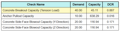
Hier zijn de resulterende verhoudingen voor iedereen afschuifcontroles.
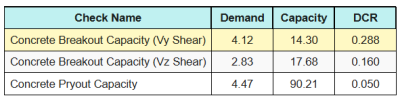
Eerste, wij controleren met Eq. (7.55) en vergelijk het resultaat met de maximale interactielimiet van 1.0.
\(IK_{\tekst{geval1}} = links(\links(\frac{N_{Ed}}{N_{Rd}}\Rechtsaf)^{1.5}\Rechtsaf) + \links(\links(\frac{V_{Ed}}{V_{Rd}}\Rechtsaf)^{1.5}\Rechtsaf)\)
\(IK_{\tekst{geval1}} = links(\links(\frac{40}{45.106}\Rechtsaf)^{1.5}\Rechtsaf) + \links(\links(\frac{4.1231}{14.296}\Rechtsaf)^{1.5}\Rechtsaf) = 0.99\)
De volgende, wij controleren met Eq. (7.56) en vergelijk het resultaat met de maximale interactielimiet van 1.2.
\(IK_{\tekst{geval2}} = frac{N_{Ed}}{N_{Rd}} + \frac{V_{Ed}}{V_{Rd}} = frac{40}{45.106} + \frac{4.1231}{14.296} = 1.1752\)
Sinds 0.99 < 1.0 en 1.175 < 1.2, de interactiecontrole betonfalen is voldoende.
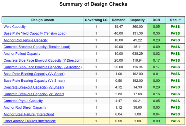
Ontwerp Samenvatting
De Skyciv Base Plate Design Software Kan automatisch een stapsgewijze berekeningsrapport genereren voor dit ontwerpvoorbeeld. Het biedt ook een samenvatting van de uitgevoerde controles en hun resulterende verhoudingen, De informatie in één oogopslag gemakkelijk te begrijpen maken. Hieronder is een sample samenvattende tabel, die is opgenomen in het rapport.
Skyciv Sample Report
Bekijk het detailniveau en de duidelijkheid die u kunt verwachten van een SkyCiv-basisplaatontwerprapport. Het rapport bevat alle belangrijke ontwerpcontroles, vergelijkingen, en resultaten gepresenteerd in een duidelijk en gemakkelijk leesbaar formaat. Het voldoet volledig aan de ontwerpnormen. Klik hieronder om een voorbeeldrapport te bekijken dat is gegenereerd met de SkyCiv-basisplaatcalculator.
(Voorbeeldrapport wordt binnenkort toegevoegd)
Koop baseplaatsoftware
Koop de volledige versie van de basisplaatontwerpmodule op zichzelf zonder andere SkyCiv -modules. Dit geeft u een volledige set resultaten voor het ontwerp van de basisplaat, inclusief gedetailleerde rapporten en meer functionaliteit.