Ontwerpvoorbeeld van basisplaat met CSA S16:19 en CSA A23.3:19
Probleemverklaring
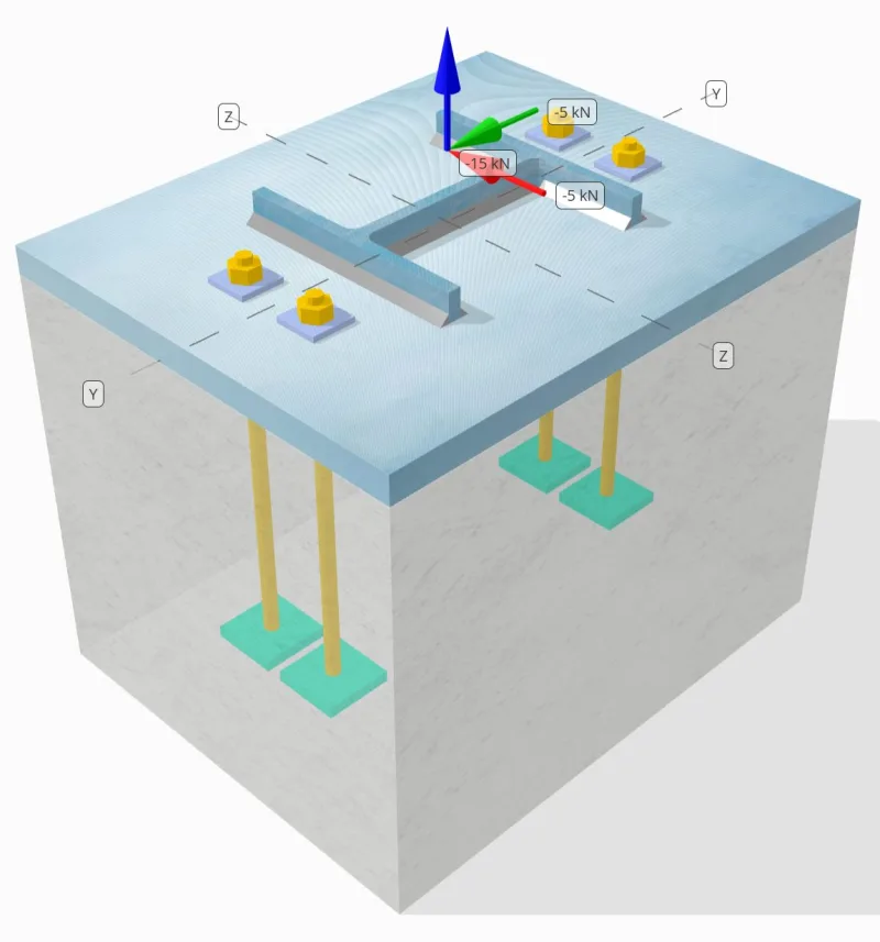
Bepaal of de ontworpen kolom-voetplaatverbinding hiervoor voldoende is 15 kN trekbelasting, 5 kN Vy schuifbelasting, en 5 kN Vz schuifbelasting.
Gegeven gegevens
Kolom:
Kolomgedeelte: HP200x54
Kolomgebied: 6840.0 mm2
Kolommateriaal: 350W
Bodemplaat:
Baseplaat afmetingen: 400 mm x 500 mm
Basisplaatdikte: 25 mm
Basisplaatmateriaal: 300W
Vocht:
Voegdikte: 0 mm
Beton:
Concrete dimensies: 400 mm x 500 mm
Betonnen dikte: 380 mm
Betonnen materiaal: 20.7 MPa
Gebarsten of ongescheurd: Gebarsten
Ankers:
Ankerdiameter: 12.7 mm
Effectieve inbeddingslengte: 300 mm
Anker einde: Rechthoekige plaat
Ingebedde plaatbreedte: 60mm
Ingebedde plaatdikte: 10 mm
Staal materiaal: F1554 Gr.55
Draden in afschuifvlak: Inbegrepen
Lassen:
Lasgrootte: 8 mm
Vulmetaalclassificatie: E43XX-X
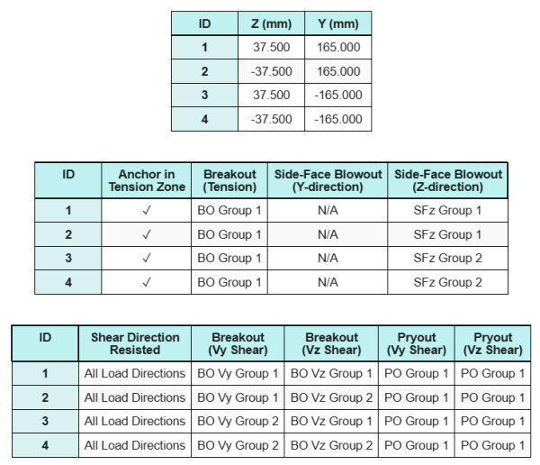
Ankergegevens (van Skyciv Calculator):
Model in SkyCiv Gratis tool
Modelleer vandaag nog het ontwerp van de basisplaat hierboven met onze gratis online tool! Geen aanmelding vereist.
Notitie
Het doel van dit ontwerpvoorbeeld is om de stapsgewijze berekeningen te demonstreren voor capaciteitscontroles met gelijktijdige schuif- en axiale belastingen. Een aantal van de vereiste controles zijn al besproken in de voorgaande ontwerpvoorbeelden. Raadpleeg de links in elke sectie.
Stapsgewijze berekeningen
Controleren #1: Lascapaciteit berekenen
Voor het bepalen van het lasvermogen bij gelijktijdige belasting, we moeten eerst de lasvraag berekenen als gevolg van de schuifbelasting en de lasvraag als gevolg van de spanning belasting. U kunt hiernaar verwijzen link voor de procedure om de lasvereisten voor afschuiving te verkrijgen, en dit link voor de spanningslasvereisten.
Voor dit ontwerp, de lasbehoefte aan de flens als gevolg van de trekbelasting blijkt als volgt te zijn, waar de spanning wordt uitgedrukt als kracht per lengte-eenheid.
\( v_{f,flg} = frac{T_{u,anker}}{l_{eff}} = frac{3.75\,\tekst{kN}}{100.5\,\tekst{mm}} = 0,037313,tekst{kN / mm} \)
Verder, de lasspanning op elk deel van de kolomsectie als gevolg van de schuifbelasting wordt bepaald als:
\( v_{fy} = frac{V_y}{L_{lassen}} = frac{5\,\tekst{kN}}{1090.6\,\tekst{mm}} = 0,0045846,tekst{kN / mm} \)
\( v_{fz} = frac{V_z}{L_{lassen}} = frac{5\,\tekst{kN}}{1090.6\,\tekst{mm}} = 0,0045846,tekst{kN / mm} \)
Omdat er sprake is van een combinatie van trek- en schuifbelastingen web, we moeten de resulterende verkrijgen. Dit wordt uitgedrukt als kracht per lengte-eenheid, wij hebben:
\(r_f = sqrt{(R_{f,\tekst{flg}})^ 2 + (v_{fy})^ 2 + (v_{fz})^ 2}\)
\( r_f = sqrt{(0.037313\,\tekst{kN / mm})^ 2 + (0.0045846\,\tekst{kN / mm})^ 2 + (0.0045846\,\tekst{kN / mm})^ 2} \)
\(r_f = 0.037873\ \tekst{kN / mm}\)
Voor de web, Er zijn alleen schuifspanningen aanwezig. Dus, de resulterende is:
\( r_f = sqrt{((v_{fy})^ 2) + ((v_{fz})^ 2)} \)
\( r_f = sqrt{((0.0045846\,\tekst{kN / mm})^ 2) + ((0.0045846\,\tekst{kN / mm})^ 2)} = 0,0064836,tekst{kN / mm} \)
De volgende, we berekenen de berekende lascapaciteit gebruik makend van CSA S16:19 Clausule 13.13.2.2. Wij nemen conservatief aan kds = 1.0, door altijd de belastingshoek in te stellen 0 jij, waarbij eventuele extra capaciteit die door de werkelijke belastingshoek wordt toegevoegd, wordt verwaarloosd.
\( v_{r,web} = 0,67phi t_wX_u = 0.67 \keer 0.67 \maal 5,657,tekst{mm} \maal 430,tekst{MPa} = 1,092,tekst{kN / mm} \)
\( v_{r,flg} = 0,67phi t_wX_u = 0.67 \keer 0.67 \maal 5,657,tekst{mm} \maal 430,tekst{MPa} = 1,092,tekst{kN / mm} \)
Voor deze lasverbinding, de elektrodesterkte overtreft niet de sterkten van het basismetaal. Daarom, de basismetaalcontrole is niet bepalend en hoeft niet te worden uitgevoerd.
Sinds 0.0064836 kN / mm < 1.092 kN / mm en 0.037873 kN / mm < 1.092 kN / mm, De lascapaciteit is voldoende.
Controleren #2: Bereken de buigcapaciteit van de basisplaat als gevolg van spanningsbelasting
Een ontwerpvoorbeeld voor het buigvloeivermogen van de basisplaat wordt al besproken in het ontwerpvoorbeeld voor spanning van de basisplaat. Voor de stapsgewijze berekening verwijzen wij u naar deze link.
Controleren #3: Bereken de trekcapaciteit van de ankerstaaf
Een ontwerpvoorbeeld voor de trekcapaciteit van de ankerstang wordt al besproken in het ontwerpvoorbeeld voor spanning van de basisplaat. Voor de stapsgewijze berekening verwijzen wij u naar deze link. Voor de stapsgewijze berekening verwijzen wij u naar deze link.
Controleren #4: Bereken de betonuitbraakcapaciteit in spanning
Een ontwerpvoorbeeld voor het vermogen van het beton bij spanningsdoorbraak wordt al besproken in het ontwerpvoorbeeld voor spanning van de basisplaat. Voor de stapsgewijze berekening verwijzen wij u naar deze link. Voor de stapsgewijze berekening verwijzen wij u naar deze link.
Controleren #5: Bereken het pull -outcapaciteit van het anker
Een ontwerpvoorbeeld voor het uittrekvermogen van het anker wordt al besproken in het ontwerpvoorbeeld voor spanning van de basisplaat. Voor de stapsgewijze berekening verwijzen wij u naar deze link. Voor de stapsgewijze berekening verwijzen wij u naar deze link.
Controleren #6: Bereken de buigcapaciteit van de instortplaat
Een ontwerpvoorbeeld voor de aanvullende controle van het buigvloeivermogen van de ingebedde plaat wordt al besproken in het Basisplaatontwerpvoorbeeld voor spanning. Voor de stapsgewijze berekening verwijzen wij u naar deze link.
Controleren #7: Bereken de side-face blowoutcapaciteit in Y-richting
Er is sprake van een zijwaartse uitbarsting langs de Y-richting niet van toepassing omdat de ankers niet dicht genoeg bij de linker- en rechterrand van de betonnen steun zijn geplaatst.
Controleren #8: Bereken side-face blowoutcapaciteit in Z-richting
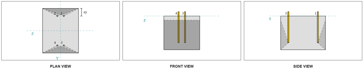
Om de te berekenen Zijwaartse klapband (SFBO) capaciteit, we bepalen eerst het totaal spankracht op de ankers die zich het dichtst bij de rand bevinden. Voor deze cheque, we zullen de capaciteit van de rand langs de evalueren Z-richting.
Omdat de falende kegelprojecties van de SFBO langs de Z-richting elkaar overlappen, de ankers worden behandeld als een ankergroep.
De totale spanningsvraag van de ankergroep wordt berekend als:
\( N_{fa} = links(\frac{N_z}{N_{een,t}}\Rechtsaf)N_{z,G1} = links(\frac{15\,\tekst{kN}}{4}\Rechtsaf) \keer 2 = 7,5,tekst{kN} \)
De volgende, We bepalen de randafstanden:
\( c_{j,min} = min(c_{\tekst{top},G1}, c_{\tekst{bodem},G1}) = min(85\,\tekst{mm}, 415\,\tekst{mm}) = 85,tekst{mm} \)
\( c_{z,min} = min(c_{\tekst{links},G1}, c_{\tekst{Rechtsaf},G1}) = min(162.5\,\tekst{mm}, 162.5\,\tekst{mm}) = 162,5,tekst{mm} \)
Met behulp van deze randafstanden, we berekenen de capaciteit van de ankergroep in overeenstemming met CSA A23.3:19 Artikel D.6.4.
\( N_{sbgr} = links(\frac{1 + \frac{c_{z,min}}{c_{j,min}}}{4} + \frac{S_{som,z,G1}}{6c_{j,min}}\Rechtsaf)13.3\links(\frac{c_{j,min}}{mm}\Rechtsaf)\sqrt{\frac{EEN_{brg}}{mm^2}}\philambda_asqrt{\frac{f'_c}{MPa}}R(N) \)
\( N_{sbgr} = links(\frac{1 + \frac{162.5\,\tekst{mm}}{85\,\tekst{mm}}}{4} + \frac{75\,\tekst{mm}}{6 \maal 85,tekst{mm}}\Rechtsaf) \keer 13.3 \keer links(\frac{85\,\tekst{mm}}{1\,\tekst{mm}}\Rechtsaf) \keer sqrt{\frac{3473.3\,\tekst{mm}^ 2}{1\,\tekst{mm}^ 2}} \keer 0.65 \keer 1 \keer sqrt{\frac{20.68\,\tekst{MPa}}{1\,\tekst{MPa}}} \keer 1 \maal 0,001,tekst{kN} \)
\( N_{sbgr} = 172.32,tekst{kN} \)
In de oorspronkelijke vergelijking, er wordt een reductiefactor toegepast als de ankerafstand kleiner is dan 6ca₁, ervan uitgaande dat de kopankers voldoende randafstand hebben. Echter, in dit ontwerpvoorbeeld, sinds ca₂ < 3ca₁, de SkyCiv-calculator past een extra reductiefactor toe om rekening te houden met de verminderde randcapaciteit.
Sinds 7.5 kN < 172.32 kN, de SFBO-capaciteit langs de Z-richting is voldoende.
Controleren #9: Bereken de uitbreekcapaciteit (Vy afschuiving)
Een ontwerpvoorbeeld voor het uitbreekvermogen van beton in Vy-afschuiving wordt al besproken in het ontwerpvoorbeeld van de basisplaat voor afschuiving. Voor de stapsgewijze berekening verwijzen wij u naar deze link.
Controleren #10: Bereken de uitbreekcapaciteit (Vz-afschuiving)
Een ontwerpvoorbeeld voor het uitbreekvermogen van beton in Vy-afschuiving wordt al besproken in het ontwerpvoorbeeld van de basisplaat voor afschuiving. Voor de stapsgewijze berekening verwijzen wij u naar deze link.
Controleren #11: Bereken de loshaalcapaciteit (Vy afschuiving)
Een ontwerpvoorbeeld voor de capaciteit van het beton tegen loswippen als gevolg van Vy-schuifkracht wordt al besproken in het Basisplaatontwerpvoorbeeld voor schuifkracht. Voor de stapsgewijze berekening verwijzen wij u naar deze link.
Controleren #12: Bereken de loshaalcapaciteit (Vz-afschuiving)
Een ontwerpvoorbeeld voor de capaciteit van het beton tegen loswippen als gevolg van Vy-schuifkracht wordt al besproken in het Basisplaatontwerpvoorbeeld voor schuifkracht. Voor de stapsgewijze berekening verwijzen wij u naar deze link.
Controleren #13: Bereken de afschuifcapaciteit van de ankerstang
Een ontwerpvoorbeeld voor de afschuifcapaciteit van de ankerstang wordt al besproken in het ontwerpvoorbeeld van de basisplaat voor afschuiving. Voor de stapsgewijze berekening verwijzen wij u naar deze link.
Controleren #14: Bereken de schuif- en trekcapaciteit van de ankerstang (CSA S16)
Om de capaciteit van de ankerstang te bepalen onder gecombineerde schuif- en axiale belastingen, we gebruiken CSA S16:19 Clausule 13.12.1.4.
De totale trekkracht die door de ankers wordt ervaren, inclusief extra buiging door excentrische schuifbelasting wordt hieronder weergegeven.
\( T_{f,totaal} = T_f + N_{fa} = 18.038,tekst{kN} + 3.75\,\tekst{kN} = 21,788,tekst{kN} \)
Gebruikmakend van de vraag- en capaciteitswaarden voor zowel uitgevoerde schuif- als trekcontroles, we berekenen nu de interactie vergelijking.
\( ik = links(\links(\frac{V_{fa}}{V_{c,zh}}\Rechtsaf)^2rechts) + \links(\links(\frac{T_{f,totaal}}{T_c}\Rechtsaf)^2rechts) \)
\( ik = links(\links(\frac{3.5355\,\tekst{kN}}{14.255\,\tekst{kN}}\Rechtsaf)^2rechts) + \links(\links(\frac{21.788\,\tekst{kN}}{28.85\,\tekst{kN}}\Rechtsaf)^2rechts) = 0.63189 \)
Sinds 0.63 < 1.0, de interactiecapaciteit van de ankerstangen volgens CSA S16 is voldoende.
Controleren #15: Bereken interactiecontroles (CSA A23.3)
Bij het controleren van de capaciteit van de ankerstang onder gecombineerde schuif- en trekbelastingen met behulp van CSA A23.3, er wordt een andere aanpak toegepast. Voor de volledigheid, wij voeren ook de CSA A23.3 interactiecontroles bij deze berekening, waaronder andere concrete interactiecontroles ook.
Hier zijn de resultaten verhoudingen voor alle CSA A23.3 spanningscontroles:
En hier zijn de resultaten verhoudingen voor alle CSA A23.3-afschuifcontroles:
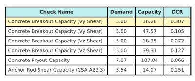
We nemen de ontwerpcontrole met de grootste verhouding en vergelijken deze met de maximale interactieverhouding CSA A23.3:19 Vergelijking D.46.
\( IK_{int} = frac{N_{fa}}{N_{ra}} + \frac{V_{fa}}{V_{ra}} = frac{15}{53.52} + \frac{5}{16.278} = 0.58743 \)
Sinds 0.587 < 1.2, de interactiecontrole is voldoende.
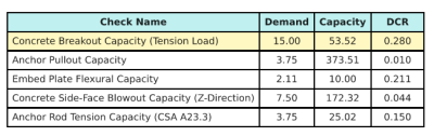
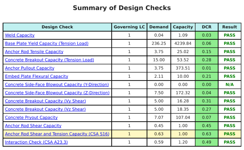
Ontwerp Samenvatting
De Skyciv Base Plate Design Software Kan automatisch een stapsgewijze berekeningsrapport genereren voor dit ontwerpvoorbeeld. Het biedt ook een samenvatting van de uitgevoerde controles en hun resulterende verhoudingen, De informatie in één oogopslag gemakkelijk te begrijpen maken. Hieronder is een sample samenvattende tabel, die is opgenomen in het rapport.
Skyciv Sample Report
Bekijk het detailniveau en de duidelijkheid die u kunt verwachten van een SkyCiv-basisplaatontwerprapport. Het rapport bevat alle belangrijke ontwerpcontroles, vergelijkingen, en resultaten gepresenteerd in een duidelijk en gemakkelijk leesbaar formaat. Het voldoet volledig aan de ontwerpnormen. Klik hieronder om een voorbeeldrapport te bekijken dat is gegenereerd met de SkyCiv-basisplaatcalculator.
Koop baseplaatsoftware
Koop de volledige versie van de basisplaatontwerpmodule op zichzelf zonder andere SkyCiv -modules. Dit geeft u een volledige set resultaten voor het ontwerp van de basisplaat, inclusief gedetailleerde rapporten en meer functionaliteit.