Base plaatontwerp voorbeeld met behulp van AISC 360-22 en ACI 318-19
Probleemverklaring
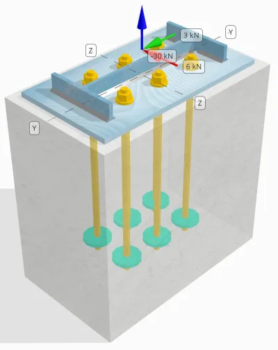
Bepaal of de ontworpen kolom-voetplaatverbinding hiervoor voldoende is 30 kN trekbelasting, 3 kN Vy schuifbelasting, en 6 kN Vz schuifbelasting.
Gegeven gegevens
Kolom:
Kolomgedeelte: B14x30
Kolomgebied: 5709.7 mm2
Kolommateriaal: A992
Bodemplaat:
Baseplaat afmetingen: 250 mm x 250 mm
Basisplaatdikte: 12 mm
Basisplaatmateriaal: A992
Vocht:
Voegdikte: 0 mm
Beton:
Concrete dimensies: 300 mm x 500 mm
Betonnen dikte: 500 mm
Betonnen materiaal: 20.7 MPa
Gebarsten of ongescheurd: Gebarsten
Ankers:
Ankerdiameter: 16 mm
Effectieve inbeddingslengte: 400 mm
Anker einde: Ronde plaat
Ingebouwde plaatdiameter: 70 mm
Ingebedde plaatdikte: 10 mm
Staal materiaal: F1554 Gr.55
Draden in afschuifvlak: Inbegrepen
Lassen:
Lasgrootte: 7 mm
Vulmetaalclassificatie: E70XX
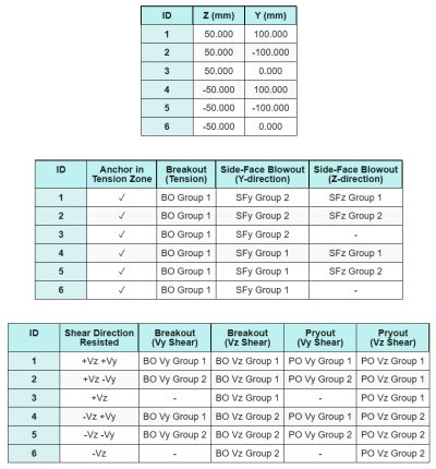
Ankergegevens (van Skyciv Calculator):
Model in SkyCiv Gratis tool
Modelleer vandaag nog het ontwerp van de basisplaat hierboven met onze gratis online tool! Geen aanmelding vereist.
Notitie
Het doel van dit ontwerpvoorbeeld is om de stapsgewijze berekeningen te demonstreren voor capaciteitscontroles met gelijktijdige schuif- en axiale belastingen. Een aantal van de vereiste controles zijn al besproken in de voorgaande ontwerpvoorbeelden. Raadpleeg de links in elke sectie.
Stapsgewijze berekeningen
Controleren #1: Lascapaciteit berekenen
Voor het bepalen van het lasvermogen bij gelijktijdige belasting, we moeten eerst de lasvraag berekenen als gevolg van de schuifbelasting en de lasvraag als gevolg van de spanning belasting. U kunt hiernaar verwijzen link voor de procedure om de lasvereisten voor afschuiving te verkrijgen, en dit link voor de spanningslasvereisten.
Voor dit ontwerp, de lasvraag op internet als gevolg van de trekbelasting blijkt als volgt te zijn, waar de spanning wordt uitgedrukt als kracht per lengte-eenheid.
\(R_{u,\tekst{web}} = frac{T_{u,\tekst{anker}}}{l_{\tekst{eff}}} = frac{5\ \tekst{kN}}{93.142\ \tekst{mm}} = 0.053681\ \tekst{kN / mm}\)
Verder, de lasspanning op elk deel van de kolomsectie als gevolg van de schuifbelasting wordt bepaald als:
\(v_{uy} = frac{V_y}{L_{\tekst{lassen}}} = frac{3\ \tekst{kN}}{1250.7\ \tekst{mm}} = 0.0023987\ \tekst{kN / mm}\)
\(v_{naar} = frac{V_z}{L_{\tekst{lassen}}} = frac{6\ \tekst{kN}}{1250.7\ \tekst{mm}} = 0.0047973\ \tekst{kN / mm}\)
Omdat er sprake is van een combinatie van trek- en schuifbelastingen web, we moeten de resulterende verkrijgen. Dit wordt uitgedrukt als kracht per lengte-eenheid, wij hebben:
\(r_u = sqrt{(R_{u,\tekst{web}})^ 2 + (v_{uy})^ 2 + (v_{naar})^ 2}\)
\(r_u = sqrt{(0.053681\ \tekst{kN / mm})^ 2 + (0.0023987\ \tekst{kN / mm})^ 2 + (0.0047973\ \tekst{kN / mm})^ 2}\)
\(r_u = 0.053949\ \tekst{kN / mm}\)
Voor de flenzen, Er zijn alleen schuifspanningen aanwezig. Dus, de resulterende is:
\(r_u = sqrt{(v_{uy})^ 2 + (v_{naar})^ 2}\)
\(r_u = sqrt{(0.0023987\ \tekst{kN / mm})^ 2 + (0.0047973\ \tekst{kN / mm})^ 2} = 0.0053636\ \tekst{kN / mm}\)
De volgende, we berekenen de lascapaciteiten. Voor de flens, wij bepalen de hoek θ de ... gebruiken Vz en Jij belastingen.
\( \theta = \tan^{-1}\!\links(\frac{v_{uy}}{v_{naar}}\Rechtsaf) = tan^{-1}\!\links(\frac{0.0023987\ \tekst{kN / mm}}{0.0047973\ \tekst{kN / mm}}\Rechtsaf) = 0.46365\ \tekst{rad} \)
bijgevolg, de kds factor en lascapaciteit worden berekend met behulp van AISC 360-22 Eq. J2-5 en Eq. J2-4.
\(zodat ingenieurs precies kunnen nagaan hoe deze berekeningen zijn gemaakt{ds} = 1.0 + 0.5(\zonder(\theta))^{1.5} = 1 + 0.5 \keer (\zonder(0.46365\ \tekst{rad}))^{1.5} = 1.1495\)
\(\phi r_{n,flg} = phi,0,6,F_{exx}\,E_w\,k_{ds} = 0.75 \keer 0.6 \keer 480\ \tekst{MPa} \keer 4.95\ \tekst{mm} \keer 1.1495 = 1.2291\ \tekst{kN / mm}\)
Voor het internet, wij berekenen de hoek θ een andere formule gebruiken. Let daar op Wauw wordt in de formule gebruikt omdat deze de belasting evenwijdig aan de lasas weergeeft.
\( \theta = \cos^{-1}\!\links(\frac{v_{uy}}{r_u}\Rechtsaf) = \cos^{-1}\!\links(\frac{0.0023987\ \tekst{kN / mm}}{0.053949\ \tekst{kN / mm}}\Rechtsaf) = 1.5263\ \tekst{rad} \)
Gebruik makend van AISC 360-22 Eq. J2-5 en Eq. J2-4, de kds factor en de resulterende lascapaciteit worden op dezelfde manier bepaald.
\(zodat ingenieurs precies kunnen nagaan hoe deze berekeningen zijn gemaakt{ds} = 1.0 + 0.5(\zonder(\theta))^{1.5} = 1 + 0.5 \keer (\zonder(1.5263\ \tekst{rad}))^{1.5} = 1.4993\)
\(\phi r_{n,web} = phi,0,6,F_{exx}\,E_w\,k_{ds} = 0.75 \keer 0.6 \keer 480\ \tekst{MPa} \keer 4.95\ \tekst{mm} \keer 1.4993 = 1.603\ \tekst{kN / mm}\)
Ten slotte, wij treden op basismetaalcontroles voor zowel de kolom als de voetplaat, verkrijg vervolgens de geldende basismetaalcapaciteit.
\( \phi r_{nbm,col} = phi,0,6,F_{u,col}\,t_{col,half} = 0.75 \keer 0.6 \keer 448.2\ \tekst{MPa} \keer 3.429\ \tekst{mm} = 0.6916\ \tekst{kN / mm} \)
\( \phi r_{nbm,bp} = phi,0,6,F_{u,bp}\,t_{bp} = 0.75 \keer 0.6 \keer 400\ \tekst{MPa} \keer 12\ \tekst{mm} = 2.1595\ \tekst{kN / mm} \)
\( \phi r_{nbm} = mingroot(\phi r_{nbm,bp},\ \phi r_{nbm,col}\groot) = min(2.1595\ \tekst{kN / mm},\ 0.6916\ \tekst{kN / mm}) = 0.6916\ \tekst{kN / mm} \)
Vervolgens vergelijken wij de capaciteiten voor hoeklassen en capaciteiten van basismetaal voor de lasvereisten bij de flenzen en lijf afzonderlijk.
Sinds 0.053949 kN / mm < 0.6916 kN / mm, De lascapaciteit is voldoende.
Controleren #2: Bereken de buigcapaciteit van de basisplaat als gevolg van spanningsbelasting
Een ontwerpvoorbeeld voor het buigvloeivermogen van de basisplaat wordt al besproken in het ontwerpvoorbeeld voor spanning van de basisplaat. Voor de stapsgewijze berekening verwijzen wij u naar deze link.
Controleren #3: Bereken de trekcapaciteit van de ankerstaaf
Een ontwerpvoorbeeld voor de trekcapaciteit van de ankerstang wordt al besproken in het ontwerpvoorbeeld voor spanning van de basisplaat. Voor de stapsgewijze berekening verwijzen wij u naar deze link. Voor de stapsgewijze berekening verwijzen wij u naar deze link.
Controleren #4: Bereken de betonuitbraakcapaciteit in spanning
Een ontwerpvoorbeeld voor het vermogen van het beton bij spanningsdoorbraak wordt al besproken in het ontwerpvoorbeeld voor spanning van de basisplaat. Voor de stapsgewijze berekening verwijzen wij u naar deze link. Voor de stapsgewijze berekening verwijzen wij u naar deze link.
Controleren #5: Bereken het pull -outcapaciteit van het anker
Een ontwerpvoorbeeld voor het uittrekvermogen van het anker wordt al besproken in het ontwerpvoorbeeld voor spanning van de basisplaat. Voor de stapsgewijze berekening verwijzen wij u naar deze link. Voor de stapsgewijze berekening verwijzen wij u naar deze link.
Controleren #6: Bereken de buigcapaciteit van de instortplaat
Een ontwerpvoorbeeld voor de aanvullende controle van het buigvloeivermogen van de ingebedde plaat wordt al besproken in het Basisplaatontwerpvoorbeeld voor spanning. Voor de stapsgewijze berekening verwijzen wij u naar deze link.
Controleren #7: Bereken de side-face blowoutcapaciteit in Y-richting
Om de te berekenen Zijwaartse klapband (SFBO) capaciteit, we bepalen eerst het totaal spankracht op de ankers die zich het dichtst bij de rand bevinden. Voor deze cheque, we zullen de capaciteit van de rand langs de evalueren Y-richting.
Omdat de falende kegelprojecties van de SFBO langs de Y-richting elkaar overlappen, de ankers worden behandeld als een ankergroep.
De totale spanningsvraag van de ankergroep wordt berekend als:
\(N_{Doen} = links(\frac{N_x}{N_{een,t}}\Rechtsaf) N_{j,G1} = links(\frac{30\ \tekst{kN}}{6}\Rechtsaf) \keer 3 = 15\ \tekst{kN}\)
De volgende, We bepalen de randafstanden:
\(c_{z,\min} = min(c_{\tekst{links},G1},\ c_{\tekst{Rechtsaf},G1}) = min(100\ \tekst{mm},\ 200\ \tekst{mm}) = 100\ \tekst{mm}\)
\(c_{j,\min} = min(c_{\tekst{top},G1},\ c_{\tekst{bodem},G1}) = min(150\ \tekst{mm},\ 150\ \tekst{mm}) = 150\ \tekst{mm}\)
Met behulp van deze randafstanden, we berekenen de capaciteit van de ankergroep in overeenstemming met ACI 318-19 Eq. (17.6.4.1).
\(N_{net zo} = links(\frac{1 + \dfrac{c_{j,\min}}{c_{z,\min}}}{4} + \frac{S_{som,j,G1}}{6\,c_{z,\min}}\Rechtsaf)\keer 13 \keer links(\frac{c_{z,\min}}{1\ \tekst{mm}}\Rechtsaf)\keer sqrt{\frac{EEN_{brg}}{\tekst{mm}^ 2}}\ \lambda_a sqrt{\frac{f_c}{\tekst{MPa}}}\keer 0.001\ \tekst{kN}\)
\(N_{net zo} = links(\frac{1 + \dfrac{150\ \tekst{mm}}{100\ \tekst{mm}}}{4} + \frac{200\ \tekst{mm}}{6\keer 100\ \tekst{mm}}\Rechtsaf)\keer 13 \keer links(\frac{100\ \tekst{mm}}{1\ \tekst{mm}}\Rechtsaf)\keer sqrt{\frac{3647.4\ \tekst{mm}^ 2}{1\ \tekst{mm}^ 2}}\keer 1 \keer sqrt{\frac{20.68\ \tekst{MPa}}{1\ \tekst{MPa}}}\keer 0.001\ \tekst{kN}\)
\(N_{net zo} = 342.16\ \tekst{kN}\)
In de oorspronkelijke vergelijking, er wordt een reductiefactor toegepast als de ankerafstand kleiner is dan 6ca₁, ervan uitgaande dat de kopankers voldoende randafstand hebben. Echter, in dit ontwerpvoorbeeld, sinds ca₂ < 3ca₁, de SkyCiv-calculator past een extra reductiefactor toe om rekening te houden met de verminderde randcapaciteit.
Uiteindelijk, de ontwerp SFBO-capaciteit is:
\(\phi N_{net zo} = \phi\,N_{net zo} = 0.7 \keer 342.16\ \tekst{kN} = 239.51\ \tekst{kN}\)
Sinds 15 kN < 239.51 kN, de SFBO-capaciteit langs de Y-richting is voldoende.
Controleren #8: Bereken side-face blowoutcapaciteit in Z-richting
Volgens dezelfde aanpak als in Controleren #7, de totale spanningsvraag van de ankergroep voor de ankers die zich het dichtst bij bevinden Z-richting rand is:
\(N_{Doen} = links(\frac{N_x}{N_{een,t}}\Rechtsaf)N_{z,G1} = links(\frac{30\ \tekst{kN}}{6}\Rechtsaf)\keer 2 = 10\ \tekst{kN}\)
De randafstanden worden berekend als:
\(c_{j,\min} = min(c_{\tekst{top},G1},\ c_{\tekst{bodem},G1}) = min(150\ \tekst{mm},\ 350\ \tekst{mm}) = 150\ \tekst{mm}\)
\(c_{z,\min} = min(c_{\tekst{links},G1},\ c_{\tekst{Rechtsaf},G1}) = min(100\ \tekst{mm},\ 100\ \tekst{mm}) = 100\ \tekst{mm}\)
De nominale SFBO-capaciteit wordt dan bepaald als:
\(N_{net zo} = links(\frac{1 + \dfrac{c_{z,\min}}{c_{j,\min}}}{4} + \frac{S_{som,z,G1}}{6\,c_{j,\min}}\Rechtsaf)\keer 13 \keer links(\frac{c_{j,\min}}{1\ \tekst{mm}}\Rechtsaf)\keer sqrt{\frac{EEN_{brg}}{\tekst{mm}^ 2}}\ \lambda_a sqrt{\frac{f_c}{\tekst{MPa}}}\keer 0.001\ \tekst{kN}\)
\(N_{net zo} = links(\frac{1 + \dfrac{100\ \tekst{mm}}{150\ \tekst{mm}}}{4} + \frac{100\ \tekst{mm}}{6\keer 150\ \tekst{mm}}\Rechtsaf)\keer 13 \keer links(\frac{150\ \tekst{mm}}{1\ \tekst{mm}}\Rechtsaf)\keer sqrt{\frac{3647.4\ \tekst{mm}^ 2}{1\ \tekst{mm}^ 2}}\keer 1 \keer sqrt{\frac{20.68\ \tekst{MPa}}{1\ \tekst{MPa}}}\keer 0.001\ \tekst{kN}\)
\(N_{net zo} = 282.65\ \tekst{kN}\)
Sinds de randafstand ca₂ is nog steeds minder dan 3ca₁, dezelfde gewijzigde reductiefactor wordt toegepast.
Uiteindelijk, de ontwerp SFBO-capaciteit is:
\(\phi N_{net zo} = \phi\,N_{net zo} = 0.7 \keer 282.65\ \tekst{kN} = 197.86\ \tekst{kN}\)
Sinds 10 kN < 197.86 kN, de SFBO-capaciteit langs de Z-richting is voldoende.
Controleren #9: Bereken de uitbreekcapaciteit (Vy afschuiving)
Een ontwerpvoorbeeld voor het uitbreekvermogen van beton in Vy-afschuiving wordt al besproken in het ontwerpvoorbeeld van de basisplaat voor afschuiving. Voor de stapsgewijze berekening verwijzen wij u naar deze link.
Controleren #10: Bereken de uitbreekcapaciteit (Vz-afschuiving)
Een ontwerpvoorbeeld voor het uitbreekvermogen van beton in Vy-afschuiving wordt al besproken in het ontwerpvoorbeeld van de basisplaat voor afschuiving. Voor de stapsgewijze berekening verwijzen wij u naar deze link.
Controleren #11: Bereken de loshaalcapaciteit (Vy afschuiving)
Een ontwerpvoorbeeld voor de capaciteit van het beton tegen loswippen als gevolg van Vy-schuifkracht wordt al besproken in het Basisplaatontwerpvoorbeeld voor schuifkracht. Voor de stapsgewijze berekening verwijzen wij u naar deze link.
Controleren #12: Bereken de loshaalcapaciteit (Vz-afschuiving)
Een ontwerpvoorbeeld voor de capaciteit van het beton tegen loswippen als gevolg van Vy-schuifkracht wordt al besproken in het Basisplaatontwerpvoorbeeld voor schuifkracht. Voor de stapsgewijze berekening verwijzen wij u naar deze link.
Controleren #13: Bereken de afschuifcapaciteit van de ankerstang
Een ontwerpvoorbeeld voor de afschuifcapaciteit van de ankerstang wordt al besproken in het ontwerpvoorbeeld van de basisplaat voor afschuiving. Voor de stapsgewijze berekening verwijzen wij u naar deze link.
Controleren #14: Bereken de afschuiving en axiale capaciteit van de ankerstang (AISC)
Om de capaciteit van de ankerstang te bepalen onder gecombineerde schuif- en axiale belastingen, we gebruiken AISC 360-22 Eq. J3-3a. In deze rekenmachine, de vergelijking wordt herschikt om het resultaat in plaats daarvan uit te drukken als de gewijzigde schuifsterkte.
De vraag afschuiven wordt gedefinieerd als de schuifbelasting per anker.
\(V_{Doen} = V_{Doen} = 2.5\ \tekst{kN}\)
De spanningsvraag wordt uitgedrukt als de trekspanning in de ankerstang.
\(f_{ut} = frac{N_{Doen}}{EEN_{hengel}} = frac{5\ \tekst{kN}}{201.06\ \tekst{mm}^ 2} = 24.868\ \tekst{MPa}\)
De gemodificeerde afschuifcapaciteit van de ankerstaaf wordt dan berekend als:
\(F'_{nv} = \min\!\links(1.3\,F_{nv} – \links(\frac{F_{nv}}{\phi F_{nt}}\Rechtsaf) f_{ut},\; F_{nv}\Rechtsaf)\)
\(F'_{nv} = \min\!\links(1.3\keer 232.69\ \tekst{MPa} – \links(\frac{232.69\ \tekst{MPa}}{0.75\keer 387.82\ \tekst{MPa}}\Rechtsaf)\keer 24.868\ \tekst{MPa},\; 232.69\ \tekst{MPa}\Rechtsaf) = 232.69\ \tekst{MPa}\)
Vervolgens vermenigvuldigen we deze sterkte met de anker gebied gebruik makend van AISC 360-22 Eq. J3-2.
\(\phi R_{n,\tekst{aisc}} = phi F’_{nv} EEN_{\tekst{hengel}} = 0.75 \keer 232.69\ \tekst{MPa} \keer 201.06\ \tekst{mm}➔⡔ Koop generieke tadalafil 35.09\ \tekst{kN}\)
Sinds 2.5 kN < 35.09 kN, de capaciteit van de ankerstang is voldoende.
Controleren #15: Bereken interactiecontroles (ACI)
Bij het controleren van de capaciteit van de ankerstang onder gecombineerde schuif- en trekbelastingen met behulp van ACI, er wordt een andere aanpak toegepast. Voor de volledigheid, wij voeren ook de ACI-interactiecontroles bij deze berekening, waaronder andere concrete interactiecontroles ook.
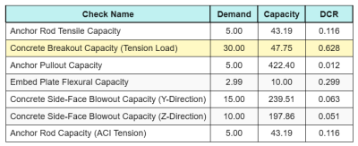
Hier zijn de resultaten verhoudingen voor alle ACI-spanningscontroles:
En hier zijn de resultaten verhoudingen voor alle ACI-afschuifcontroles:
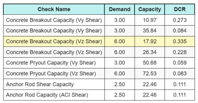
We krijgen de cheque met de grootste ratio en vergelijken deze met de maximale interactieratio ACI 318-19 Eq. 17.8.3.
\(IK_{int} = frac{N_{Doen}}{\phi N_n} + \frac{V_{Doen}}{\phi V_n} = frac{30}{47.749} + \frac{6}{17.921} = 0.96308\)
Sinds 0.96 < 1.2, de interactiecontrole is voldoende.
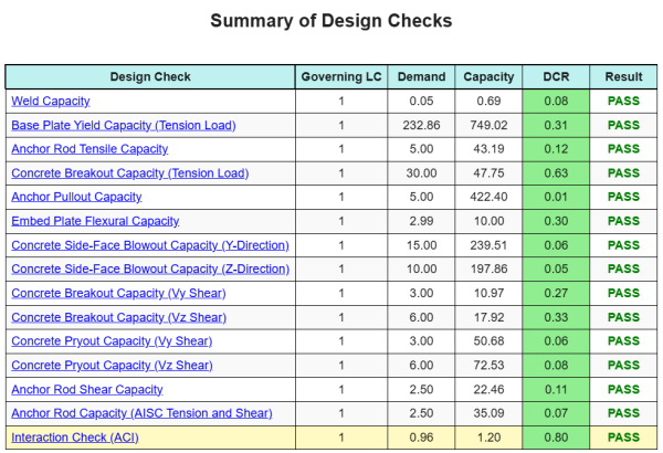
Ontwerp Samenvatting
De Skyciv Base Plate Design Software Kan automatisch een stapsgewijze berekeningsrapport genereren voor dit ontwerpvoorbeeld. Het biedt ook een samenvatting van de uitgevoerde controles en hun resulterende verhoudingen, De informatie in één oogopslag gemakkelijk te begrijpen maken. Hieronder is een sample samenvattende tabel, die is opgenomen in het rapport.
Skyciv Sample Report
Bekijk het detailniveau en de duidelijkheid die u kunt verwachten van een SkyCiv-basisplaatontwerprapport. Het rapport bevat alle belangrijke ontwerpcontroles, vergelijkingen, en resultaten gepresenteerd in een duidelijk en gemakkelijk leesbaar formaat. Het voldoet volledig aan de ontwerpnormen. Klik hieronder om een voorbeeldrapport te bekijken dat is gegenereerd met de SkyCiv-basisplaatcalculator.
Koop baseplaatsoftware
Koop de volledige versie van de basisplaatontwerpmodule op zichzelf zonder andere SkyCiv -modules. Dit geeft u een volledige set resultaten voor het ontwerp van de basisplaat, inclusief gedetailleerde rapporten en meer functionaliteit.