基本板设计示例使用en 1993-1-8:2005, 在 1993-1-1:2005, 在 1992-1-1:2004, 和EN 1992-4:2018.
问题陈述
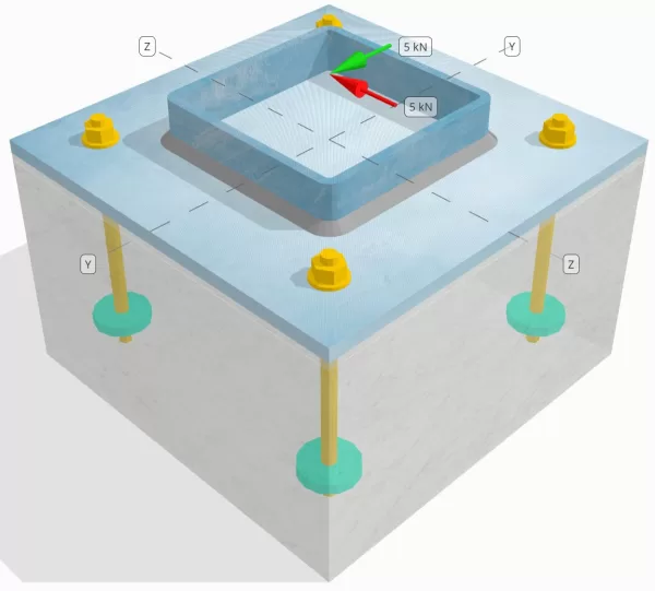
确定设计的列板连接是否足够 您= 5-kn 和 vz = 5-kn 剪力.
给定数据
柱:
列部分: SHS 180x180x8
列区域: 5440 毫米2
列材料: S235
底盘:
基板尺寸: 350 毫米× 350 毫米
基板厚度: 12 毫米
底板材料: S235
灌浆:
灌浆厚度: 6 毫米
灌浆材料: ≥ 30 兆帕
具体:
混凝土尺寸: 350 毫米× 350 毫米
混凝土厚度: 350 毫米
混凝土材料: C25/30
破裂或无裂缝: 破裂
锚:
锚直径: 12 毫米
有效嵌入长度: 150 毫米
嵌入式板直径: 60 毫米
嵌入式板厚度: 10 毫米
锚材料: 8.8
其他信息:
- 非场合锚.
- 用切线的锚.
- K7锚钢剪切故障的因子: 1.0
- 紧固件的约束程度: 没有约束
焊缝:
焊接类型: 圆角焊缝
焊接腿尺寸: 8毫米
填充金属分类: E35
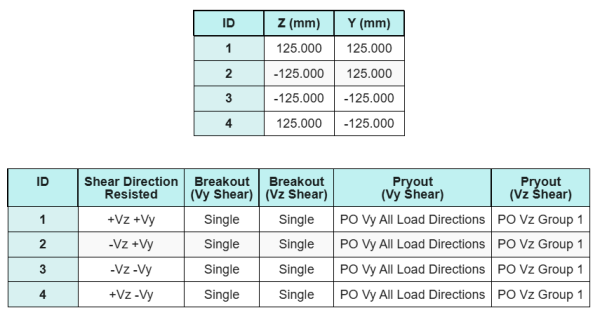
锚数据 (从 SkyCiv计算器):
SkyCiv 免费工具中的模型
立即使用我们的免费在线工具对上面的底板设计进行建模! 无需注册.
定义
负载路径:
的 SkyCiv 底板设计软件 跟随 在 1992-4:2018 用于锚杆设计. 施加到柱上的剪切荷载通过焊缝将其转移到底板上,然后通过锚杆转移到支撑混凝土中. 在此示例中不考虑摩擦和剪切凸耳, 由于这些机制在当前软件中不支持.
锚群:
该软件包含一个直观功能,该功能识别哪些锚是用于评估的锚点的一部分 混凝土剪切突破 和 具体的剪切撬 失败.
一个 锚群 被定义为两个或多个锚,并具有重叠的预防阻力区域. 在这种情况下, 锚一起行动, 并且它们的组合电阻被检查针对该组的施加载荷.
一个 单锚 被定义为锚点,其投影阻力区域不会与其他任何. 在这种情况下, 锚独自行动, 并直接检查锚上施加的剪切力,以其单独的电阻检查.
在评估剪切相关的故障模式时.
分步计算
检查一下 #1: 计算焊接容量
我们假设 电压 剪切负荷被 顶部和底部焊缝, 而 你 剪切负荷仅由 左右焊缝.
确定焊接能力 顶部和底部焊缝, 我们首先计算他们 总焊缝长度.
\(
L_{w,顶部&底部} = 2 \剩下(b_{上校} – 2t_{上校} – 2r_{上校}\对)
= 2 \时代左(180 \,\文本{毫米} – 2 \次 8 \,\文本{毫米} – 2 \次 4 \,\文本{毫米}\对)
= 312 \,\文本{毫米}
\)
下一个, 我们计算 焊缝的应力.
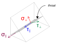
请注意,应用的VZ剪切作用于焊缝轴平行, 没有其他力量. 这意味着垂直应力可以为零, 只有 剪切应力在平行方向上 需要计算.
\(
\sigma_{\人} = frac{ñ}{(L_{w,顶部&底部})\,a\sqrt{2}}
= frac{0 \,\文本{千牛}}{(312 \,\文本{毫米}) \次 5.657 \,\文本{毫米} \次 sqrt{2}}
= 0
\)
\(
\你的_{\人} = frac{0}{(L_{w,顶部&底部})\,a\sqrt{2}}
= frac{0 \,\文本{千牛}}{(312 \,\文本{毫米}) \次 5.657 \,\文本{毫米} \次 sqrt{2}}
= 0
\)
\(
\你的_{\平行} = frac{V_{与}}{(L_{w,顶部&底部})\,一个}
= frac{5 \,\文本{千牛}}{(312 \,\文本{毫米}) \次 5.657 \,\文本{毫米}}
= 2.8329 \,\文本{兆帕}
\)
使用 在 1993-1-8:2005, 情商. 4.1, 设计焊接应力是使用定向方法获得的.
\(
F_{w,ED1} = sqrt{ (\sigma_{\人})^ 2 + 3 \剩下( (\你的_{\人})^ 2 + (\你的_{\平行})^2 对) }
= sqrt{ (0)^ 2 + 3 \时代左( (0)^ 2 + (2.8329 \,\文本{兆帕})^2 对) }
= 4.9067 \,\文本{兆帕}
\)
此外, 设计的正常应力, 每 在 1993-1-8:2005, 情商. 4.1, 被视为零, 以来 没有正常应力 在场.
\(
F_{w,ED2} = \sigma_{\人} = 0
\)
现在, 让我们评估 左右焊缝. 与顶部和底部焊缝一样, 我们首先计算 总焊接长度.
\(
L_{w,left\&对} = 2 \剩下(d_{上校} – 2t_{上校} – 2r_{上校}\对)
= 2 \时代左(180 \,\文本{毫米} – 2 \次 8 \,\文本{毫米} – 2 \次 4 \,\文本{毫米}\对)
= 312 \,\文本{毫米}
\)
然后,我们计算 焊接应力.
\(
\sigma_{\人} = frac{ñ}{(L_{w,left\&对})\,a\sqrt{2}}
= frac{0 \,\文本{千牛}}{(312 \,\文本{毫米}) \次 5.657 \,\文本{毫米} \次 sqrt{2}}
= 0
\)
\(
\你的_{\人} = frac{0}{(L_{w,left\&对})\,a\sqrt{2}}
= frac{0 \,\文本{千牛}}{(312 \,\文本{毫米}) \次 5.657 \,\文本{毫米} \次 sqrt{2}}
= 0
\)
\(
\你的_{\平行} = frac{v_y}{(L_{w,left\&对})\,一个}
= frac{5 \,\文本{千牛}}{(312 \,\文本{毫米}) \次 5.657 \,\文本{毫米}}
= 2.8329 \,\文本{兆帕}
\)
使用 在 1993-1-8:2005, 情商. 4.1, 我们确定设计焊接应力和碱金属检查的正常应力.
\(
F_{w,ED1} = sqrt{ \剩下( \sigma_{\人} \对)^ 2 + 3 \剩下( \剩下( \你的_{\人} \对)^ 2 + \剩下( \你的_{\平行} \对)^2 对) }
\)
\(
F_{w,ED1} = sqrt{ \剩下( 0 \对)^ 2 + 3 \时代左( \剩下( 0 \对)^ 2 + \剩下( 2.8329 \,\文本{兆帕} \对)^2 对) }
\)
\(
F_{w,ED1} = 4.9067 \,\文本{兆帕}
\)
下一步是确定 管理焊接压力 在顶部/底部焊缝和左/右焊缝之间. 因为焊缝长度相等并且施加的载荷具有相同的大小, 由此产生的焊接应力相等.
\(
F_{w,ED1} = \max(F_{w,ED1}, \, F_{w,ED1})
= \max(4.9067 \,\文本{兆帕}, \, 4.9067 \,\文本{兆帕})
= 4.9067 \,\文本{兆帕}
\)
母材金属应力保持为零.
\(
F_{w,ED2} = \max(F_{w,ED2}, \, F_{w,ED2}) = \max(0, \, 0) = 0
\)
现在, 我们计算焊接能力. 第一, 的电阻 角焊缝 被计算. 然后, 的电阻 贱金属 已确定. 使用英文 1993-1-8:2005, 情商. 4.1, 容量计算如下:
\(
F_{w,路德1} = frac{f_u}{\beta_w \left(\伽玛_{M2,焊接}\对)}
= frac{360 \,\文本{兆帕}}{0.8 \次 (1.25)}
= 360 \,\文本{兆帕}
\)
\(
F_{w,路数2} = frac{0.9 f_u}{\伽玛_{M2,焊接}}
= frac{0.9 \次 360 \,\文本{兆帕}}{1.25}
= 259.2 \,\文本{兆帕}
\)
最后, 我们将焊接应力与焊接能力进行比较, 以及母材应力与母材能力.
以来 4.9067 兆帕 < 360 兆帕 和 0 兆帕 < 259.2 兆帕, 焊接连接的容量为 充足的.
检查一下 #2: 计算由于Vy剪切的混凝土突破能力
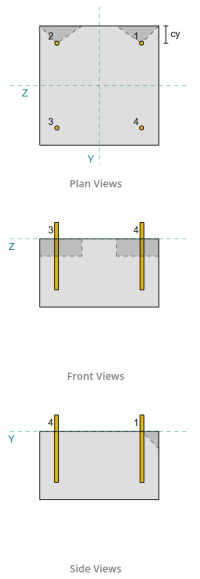
遵循以下规定 在 1992-4:2018, 评估垂直于所施加载荷的边缘是否存在剪切破坏失效. 只有 距离该边缘最近的锚点 被视为已订婚, 而假设其余的锚不能抵抗剪力.
这些边缘锚必须具有大于10·Hef和60·D的较大的混凝土边缘距离, 哪里 有 是嵌入的长度和 d 是锚直径. 如果未满足这种情况, 底板的厚度必须小于0.25·Hef.
如果要求 在 1992-4:2018, 条款 7.2.2.5(1), 不满意, SkyCiv软件无法进行设计检查, 建议用户参考其他相关标准.
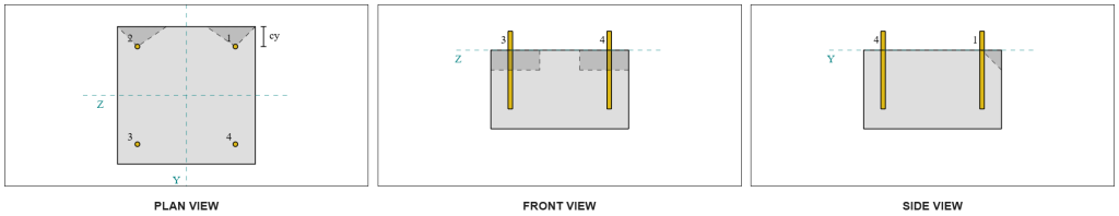
从SkyCiv软件结果, 边缘锚作为 单锚, 由于他们的投影区没有重叠. 为此计算, 锚 1 将被考虑.
计算锚携带的VY剪切负荷的部分 1, 总VY剪切剪切分布在最接近边缘的锚点中. 这给了 垂直力 在锚点上 1.
\(
V_{\人} = frac{v_y}{n_{一个,s}}
= frac{5 \,\文本{千牛}}{2}
= 2.5 \,\文本{千牛}
\)
为了 平行力, 假定所有锚点都平等地抵抗负载. 因此, 负载的并行组件计算为:
\(
V_{\平行} = frac{v_z}{n_{无}}
= frac{5 \,\文本{千牛}}{4}
= 1.25 \,\文本{千牛}
\)
的 总剪切负荷 在锚点上 1 因此:
\(
V_{埃德} = sqrt{ \剩下( V_{\人} \对)^ 2 + \剩下( V_{\平行} \对)^ 2 }
\)
\(
V_{埃德} = sqrt{ \剩下( 2.5 \,\文本{千牛} \对)^ 2 + \剩下( 1.25 \,\文本{千牛} \对)^ 2 } = 2.7951 \,\文本{千牛}
\)
容量计算的第一部分是确定 alpha和beta因素. 我们使用 在 1992-4:2018, 条款 7.2.2.5, 设置 LF维度, 和 方程 7.42 和 7.43 确定因素.
\(
l_f = \min(H_{ef}, \, 12d_{无})
= min(150 \,\文本{毫米}, \, 12 \次 12 \,\文本{毫米})
= 144 \,\文本{毫米}
\)
\(
\alpha = 0.1 \剩下(\压裂{l_f}{C_{1,s1}}\对)^{0.5}
= 0.1 \时代左(\压裂{144 \,\文本{毫米}}{50 \,\文本{毫米}}\对)^{0.5}
= 0.16971
\)
\(
\beta = 0.1 \剩下(\压裂{d_{无}}{C_{1,s1}}\对)^{0.2}
= 0.1 \时代左(\压裂{12 \,\文本{毫米}}{50 \,\文本{毫米}}\对)^{0.2}
= 0.07517
\)
下一步是计算 紧固件的特征性电阻的初始值. 使用 在 1992-4:2018, 方程 7.41, 值是:
\(
V^{0}_{检查锚容量,C} = k_9 \left( \压裂{d_{无}}{\文本{毫米}} \对)^{\α}
\剩下( \压裂{l_f}{\文本{毫米}} \对)^{\由使用公式计算的最小值控制}
\sqrt{ \压裂{F_{钢底板设计欧洲规范}}{\文本{兆帕}} }
\剩下( \压裂{C_{1,s1}}{\文本{毫米}} \对)^{1.5} ñ
\)
\(
V^{0}_{检查锚容量,C} = 1.7 \时代左( \压裂{12 \,\文本{毫米}}{1 \,\文本{毫米}} \对)^{0.16971}
\时代左( \压裂{144 \,\文本{毫米}}{1 \,\文本{毫米}} \对)^{0.07517}
\次 sqrt{ \压裂{20 \,\文本{兆帕}}{1 \,\文本{兆帕}} }
\时代左( \压裂{50 \,\文本{毫米}}{1 \,\文本{毫米}} \对)^{1.5}
\次 0.001 \,\文本{千牛}
\)
\(
V^{0}_{检查锚容量,C} = 5.954 \,\文本{千牛}
\)
然后, 我们计算 参考投影区域 单锚, 下列的 在 1992-4:2018, 方程 7.44.
\(
一个_{C,V}^{0} = 4.5 \剩下( C_{1,s1} \对)^ 2
= 4.5 \时代左( 50 \,\文本{毫米} \对)^ 2
= 11250 \,\文本{毫米}^ 2
\)
在那之后, 我们计算 实际投影区域 锚 1.
\(
b_{C,V} = min(C_{剩下,s1}, \, 1.5C_{1,s1}) + \分(C_{对,s1}, \, 1.5C_{1,s1})
\)
\(
b_{C,V} = min(300 \,\文本{毫米}, \, 1.5 \次 50 \,\文本{毫米}) + \分(50 \,\文本{毫米}, \, 1.5 \次 50 \,\文本{毫米}) = 125 \,\文本{毫米}
\)
\(
H_{C,V} = min(1.5C_{1,s1}, \, t_{浓}) = min(1.5 \次 50 \,\文本{毫米}, \, 200 \,\文本{毫米}) = 75 \,\文本{毫米}
\)
\(
一个_{C,V} = H_{C,V} b_{C,V} = 75 \,\文本{毫米} \次 125 \,\文本{毫米} = 9375 \,\文本{毫米}^ 2
\)
我们还需要计算剪切突破的参数. 我们使用 在 1992-4:2018, 方程 7.4, 为了获取有关的因素 压力分布的干扰, 方程 7.46 对于说明的因素 成员厚度, 和 方程 7.48 对于说明的因素 斜向边缘的剪切负荷的影响. 这些计算如下:
\(
\psi_{s,V} = min left( 0.7 + 0.3 \剩下( \压裂{C_{2,s1}}{1.5C_{1,s1}} \对), \, 1.0 \对)
= min left( 0.7 + 0.3 \时代左( \压裂{50 \,\文本{毫米}}{1.5 \次 50 \,\文本{毫米}} \对), \, 1 \对)
= 0.9
\)
\(
\psi_{H,V} = max left( \剩下( \压裂{1.5C_{1,s1}}{t_{浓}} \对)^{0.5}, \, 1 \对)
= max left( \剩下( \压裂{1.5 \次 50 \,\文本{毫米}}{200 \,\文本{毫米}} \对)^{0.5}, \, 1 \对)
= 1
\)
\(
\α_{V} = tan^{-1} \剩下( \压裂{V_{\平行}}{V_{\人}} \对)
= tan^{-1} \剩下( \压裂{1.25 \,\文本{千牛}}{2.5 \,\文本{千牛}} \对)
= 0.46365 \,\文本{工作}
\)
\(
\psi_{\α,V} = max left(
\sqrt{ \压裂{1}{(\cos(\α_{V}))^ 2 + \剩下( 0.5 \, (\没有(\α_{V})) \对)^ 2 } }, \, 1 \对)
\)
\(
\psi_{\α,V} = max left(
\sqrt{ \压裂{1}{(\cos(0.46365 \,\文本{工作}))^ 2 + \剩下( 0.5 \times \sin(0.46365 \,\文本{工作}) \对)^ 2 } }, \, 1 \对)
\)
\(
\psi_{\α,V} = 1.0847
\)
确定α因子时的一个重要注意事项是确保正确识别垂直剪切和平行剪切.
最后, 我们计算 突破性阻力 使用单锚的 在 1992-4:2018, 方程 7.1.
\(
V_{检查锚容量,C} = v^0_{检查锚容量,C} \剩下(\压裂{一个_{C,V}}{a^0_{C,V}}\对)
\psi_{s,V} \psi_{H,V} \psi_{欧共体,V} \psi_{\α,V} \psi_{检查锚容量,V}
\)
\(
V_{检查锚容量,C} = 5.954 \,\文本{千牛} \时代左(\压裂{9375 \,\文本{毫米}^ 2}{11250 \,\文本{毫米}^ 2}\对)
\次 0.9 \次 1 \次 1 \次 1.0847 \次 1
= 4.8435 \,\文本{千牛}
\)
应用部分因素, 设计阻力是 3.23 千牛.
\(
V_{路,C} = frac{V_{检查锚容量,C}}{\伽玛_{检查锚容量}}
= frac{4.8435 \,\文本{千牛}}{1.5}
= 3.229 \,\文本{千牛}
\)
以来 2.7951 千牛 < 3.229 千牛, VY剪切的剪切突破能力是 充足的.
检查一下 #3: 计算由于VZ剪切而导致的混凝土突破能力
使用相同的方法来确定垂直于VZ剪切的边缘的能力.
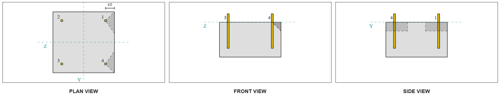
由于对称设计, 抵抗VZ剪切的锚也被确定为 单锚. 让我们考虑一下 锚 1 再次计算.
计算 垂直载荷 在锚点上 1, 我们将VZ剪切划分除以仅近边缘的锚总数. 计算 并行负载 在锚点上 1, 我们将VY剪切片除以锚的总数.
\(
V_{\人} = frac{V_{与}}{n_{一个,s}}
= frac{5 \,\文本{千牛}}{2}
= 2.5 \,\文本{千牛}
\)
\(
V_{\平行} = frac{V_{和}}{n_{无}}
= frac{5 \,\文本{千牛}}{4}
= 1.25 \,\文本{千牛}
\)
\(
V_{埃德} = sqrt{ \剩下( V_{\人} \对)^ 2 + \剩下( V_{\平行} \对)^ 2 }
\)
\(
V_{埃德} = sqrt{ \剩下( 2.5 \,\文本{千牛} \对)^ 2 + \剩下( 1.25 \,\文本{千牛} \对)^ 2 }
= 2.7951 \,\文本{千牛}
\)
使用类似的方法检查 #2, 结果 突破性阻力 对于垂直于VZ剪切的边缘是:
\(
V_{路,C} = frac{V_{检查锚容量,C}}{\伽玛_{检查锚容量}}
= frac{4.8435 \,\文本{千牛}}{1.5}
= 3.229 \,\文本{千牛}
\)
以来 2.7951 千牛 < 3.229 千牛, VZ剪切的剪切突破能力是 充足的.
检查一下 #4: 计算具体的撬动能力
计算 剪切撬动 涉及确定 锚点反对紧张突破的标称能力. 张力突破能力的参考是 在 1992-4:2018, 条款 7.2.1.4. 关于紧张突破的详细讨论已经在 SkyCiv设计示例带有张力负载 并且不会在此设计示例中重复.
从SkyCiv软件计算中, 本节的张力突破能力是 44.61 千牛.
然后我们使用 在 1992-4:2018, 等式7.39a, 获得设计特性阻力. 使用 k8 = 2, 容量是 59.48 千牛.
\(
V_{路,cp} = frac{k_8 n_{背景}}{\gamma_c}
= frac{2 \次 44.608 \,\文本{千牛}}{1.5}
= 59.478 \,\文本{千牛}
\)
在剪切pryout检查中, 所有锚都有效 抵抗完整的剪切负荷. 从SkyCiv软件生成的图像, 所有失效锥投影彼此重叠, 使锚充当 锚群.
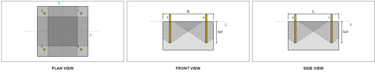
因此, 锚杆组所需的阻力是总的合成剪切荷载 7.07 千牛.
\(
V_{资源} = sqrt{(v_y)^ 2 + (v_z)^ 2}
= sqrt{(5 \,\文本{千牛})^ 2 + (5 \,\文本{千牛})^ 2}
= 7.0711 \,\文本{千牛}
\)
\(
V_{埃德} = 左(\压裂{V_{资源}}{n_{无}}\对) n_{一个,G1}
= 左(\压裂{7.0711 \,\文本{千牛}}{4}\对) \次 4
= 7.0711 \,\文本{千牛}
\)
以来 7.0711 千牛 < 59.478 千牛, 剪切撬出能力为 充足的.
检查一下 #5: 计算锚杆剪切能力
锚杆抗剪承载力的计算取决于是否用力臂施加剪切荷载. 确定这一点, 我们指的是 在 1992-4:2018, 条款 6.2.2.3, 其中灌浆的厚度和材料, 设计中的紧固件数量, 紧固件的间距, 并检查其他因素.
的 SkyCiv底板设计软件 执行所有必要的检查以确定是否 剪切载荷在有或没有杠杆臂的情况下作用. 对于本设计示例, 确定剪切载荷为 不是 与杠杆臂一起应用. 因此, 我们用 在 1992-4:2018, 条款 7.2.2.3.1, 对于容量方程.
我们首先使用使用钢紧固件的特性电阻 在 1992-4:2018, 方程 7.34.
\(
v^0_{检查锚容量,s} = k_6 a_s f_{ü,无}
= 0.5 \次 113.1 \,\文本{毫米}^2 times 800 \,\文本{兆帕}
= 45.239 \,\文本{千牛}
\)
下一个, 我们将因素应用于 延性 单锚或锚组的, 服用 K7 = 1.
\(
V_{检查锚容量,s} = k_7 v^{0}_{检查锚容量,s}
= 1 \次 45.239 \,\文本{千牛}
= 45.239 \,\文本{千牛}
\)
然后我们获得 钢剪切故障的部分因素 使用 在 1992-4:2018, 桌子 4.1. 与 8.8 材料, 由此产生的部分因素是:
\(
\伽玛_{检查锚容量,剪力}
= max left( 1.0 \剩下( \压裂{F_{ü,无}}{F_{和,无}} \对), \, 1.25 \对)
= max left( 1 \时代 frac{800 \,\文本{兆帕}}{640 \,\文本{兆帕}}, \, 1.25 \对)
= 1.25
\)
将此因素应用于特征性抗性, 设计阻力是 36.19 千牛.
\(
V_{路,s} = frac{V_{检查锚容量,s}}{\伽玛_{检查锚容量,剪力}}
= frac{45.239 \,\文本{千牛}}{1.25}
= 36.191 \,\文本{千牛}
\)
的 所需的剪切阻力 每锚杆是由此产生的剪切负荷除以锚杆的总数, 计算到 1.77 千牛.
\(
V_{埃德} = frac{\sqrt{ (v_y)^ 2 + (v_z)^ 2 }}{n_{无}}
\)
\(
V_{埃德} = frac{\sqrt{ (5 \,\文本{千牛})^ 2 + (5 \,\文本{千牛})^ 2 }}{4}
= 1.7678 \,\文本{千牛}
\)
以来 1.7678 千牛 < 36.191 千牛, 锚杆钢剪切能力是 充足的.
检查一下 #6: 计算底板承载力
SkyCiv 还使用一些参数自动计算地面雪荷载 底板承载力检查 在软件的后续更新中引入. 请 参考这个链接 计算示例和详细说明.
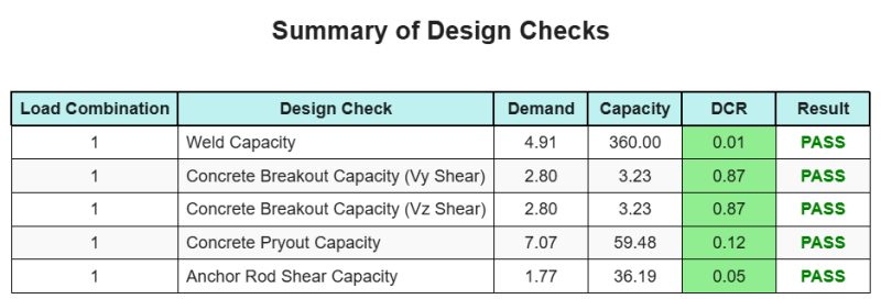
设计概要
的 SkyCiv底板设计软件 可以自动为此设计示例生成逐步计算报告. 它还提供了执行的检查及其结果比率的摘要, 一目了然地使信息易于理解. 以下是示例摘要表, 报告中包括.
SkyCiv样本报告
查看 SkyCiv 底板设计报告的详细程度和清晰度. 该报告包括所有关键的设计检查, 方程式, 并以清晰易读的格式呈现结果. 完全符合设计标准. 单击下面查看使用 SkyCiv 底板计算器生成的示例报告.
购买基板软件
单独购买基本板设计模块的完整版本,而没有任何其他SkyCiv模块. 这为您提供了底板设计的完整结果, 包括详细报告和更多功能.