如何使用刚性连接对堆叠梁建模
只需指定成员 “类型” 作为 “刚性连杆” 创建一个作为刚性链接的成员. 完成此操作后,您会看到刚性连接是用浅灰色绘制的,并且有一个 “[R” 旁边的符号:

刚性链接可用于定义涉及堆叠梁或构件的结构之间的刚性连接. 它们通常被认为是连接成员的假想刚性链接,因此它们可以一起平移和/或旋转. 刚性连杆也可用于手动控制构件偏移. 另外, 您可以更改刚性链接中的固定/释放,以控制它对所连接对象的作用力和影响.
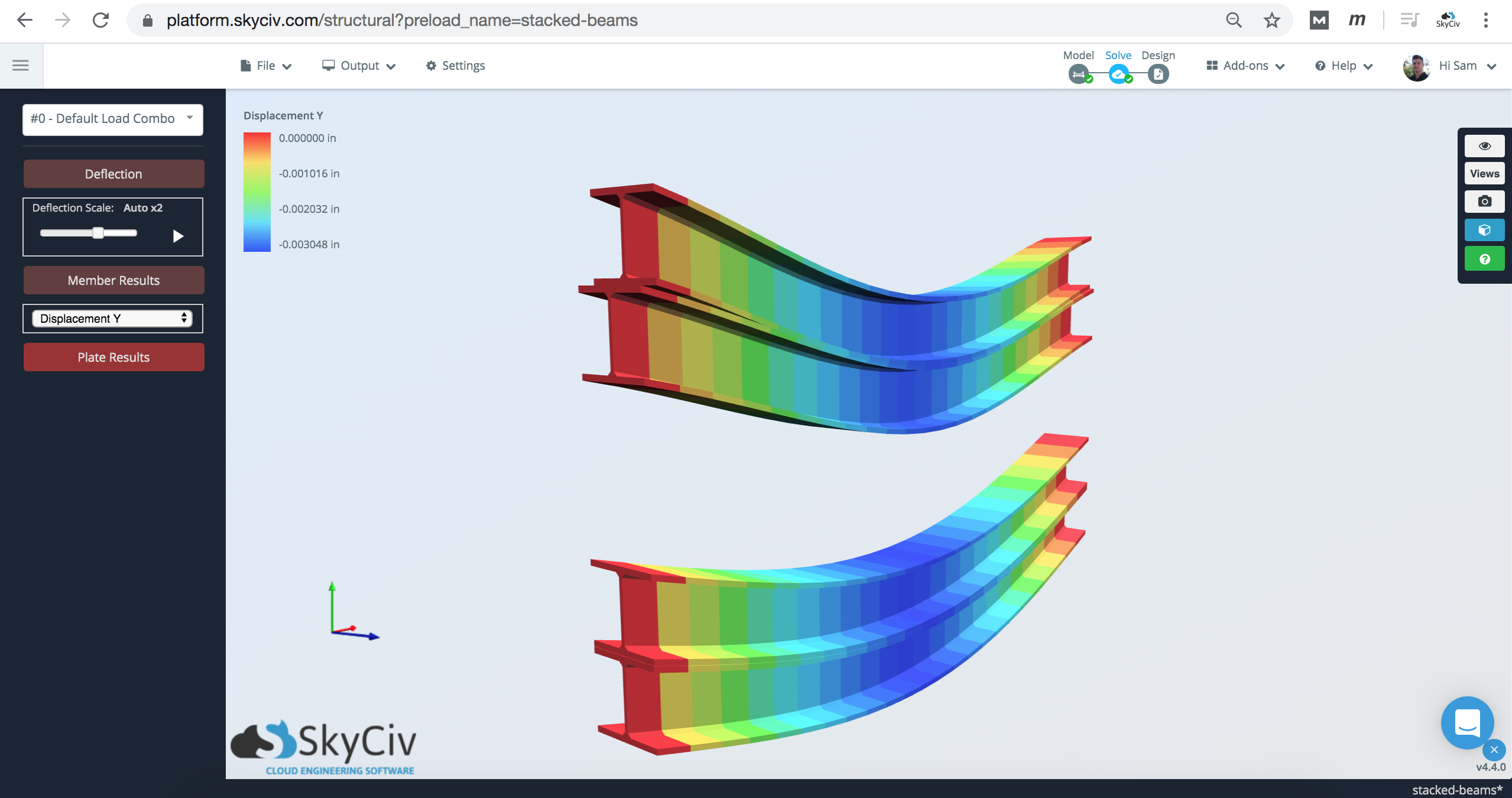
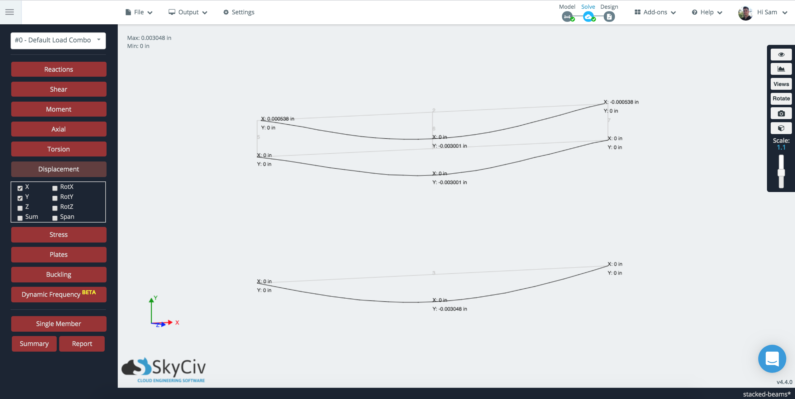
看分析结果, 你可以看到当顶梁被加载时, 并偏转, 下面的光束也是:
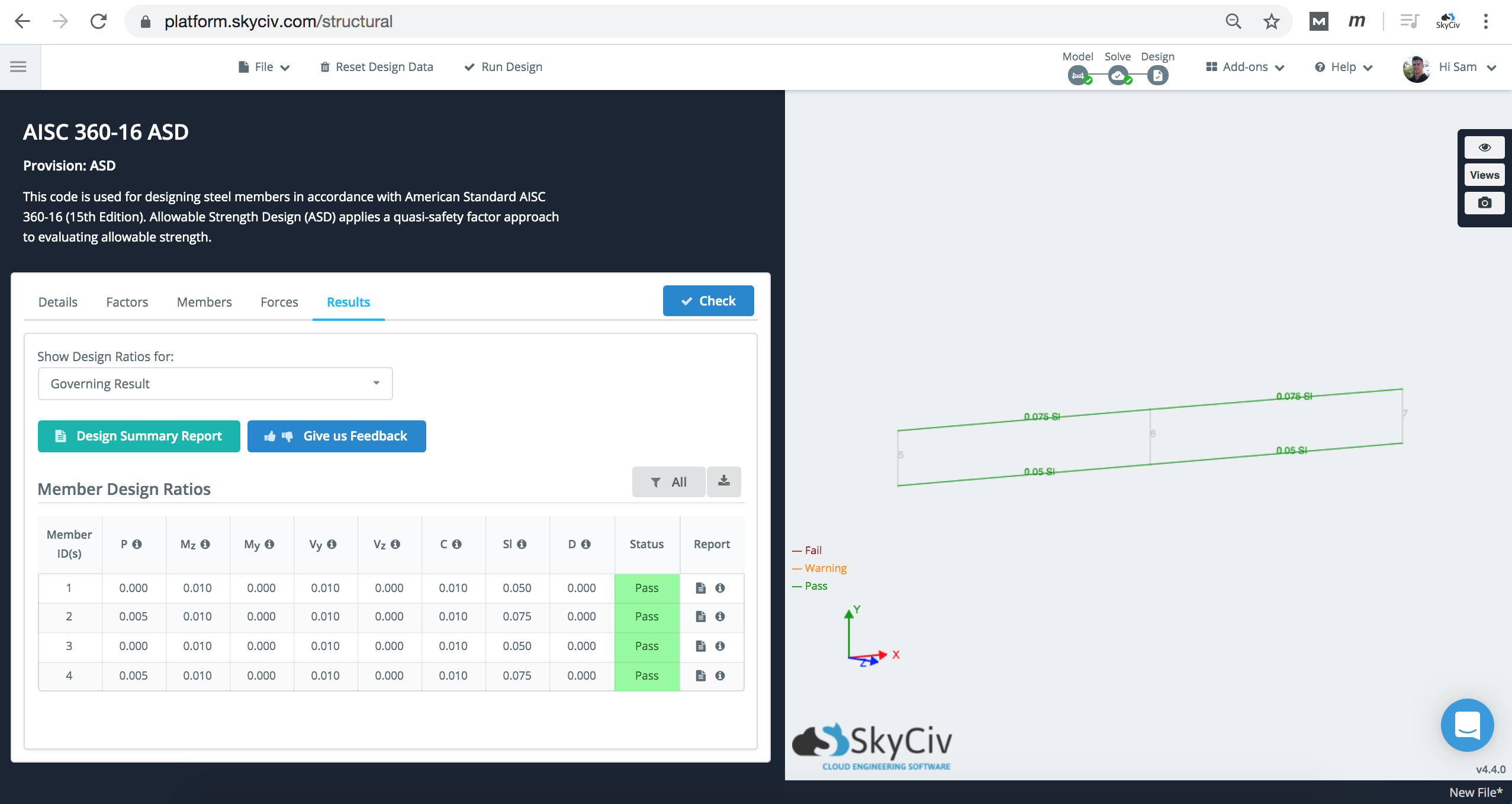
成员设计检查仍将运行, 然而, 重要的是要考虑软件在理解无支撑长度和杆件末端固定方面的局限性. 在这种情况下, Lb 应根据您的设计需要进行调整.
C3.1.2.1-6 2: 在截面生成器中使用自定义形状
上述的另一种方法是使用 SkyCiv Section Builder 对两个模型进行建模, 并将其视为一个元素:
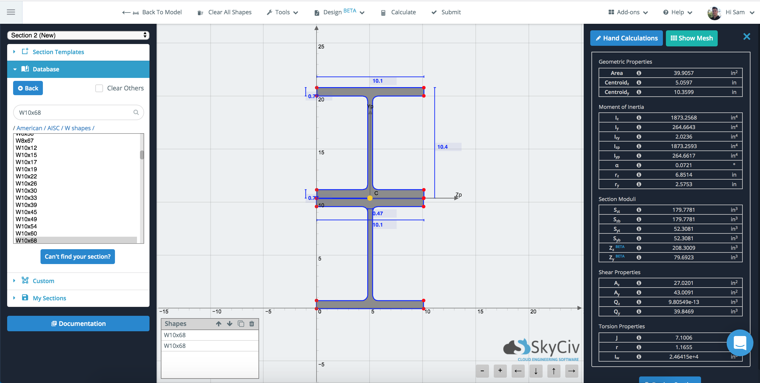
这将使用 FEA 来计算这个“单个”的几何属性’ 部分. 然后它将使用这些几何属性以及整个线元素. 可以在以下文档页面上查看有关此方法的更多信息: SkyCiv 中的复合和组合形状
结果比较
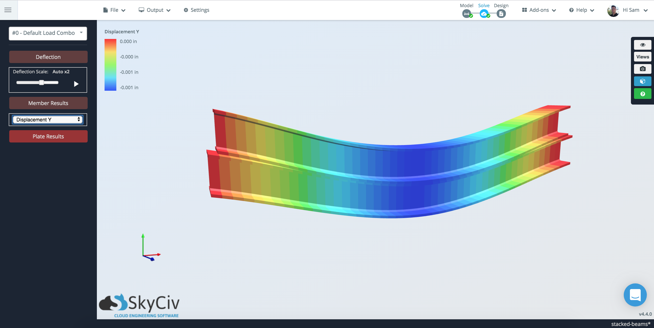
将两种方法一起建模时, 偏转的结果非常一致:
由于成员仅在沿梁的某些点处链接, 梁的连通性存在差异. 在底部 (部分生成器方法), 该元素被视为一件, 而在刚性连接方法中, 它只连接在 3 沿梁跨度的点.