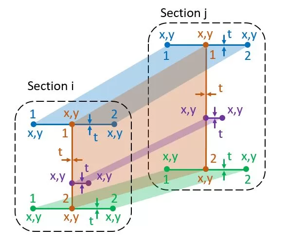
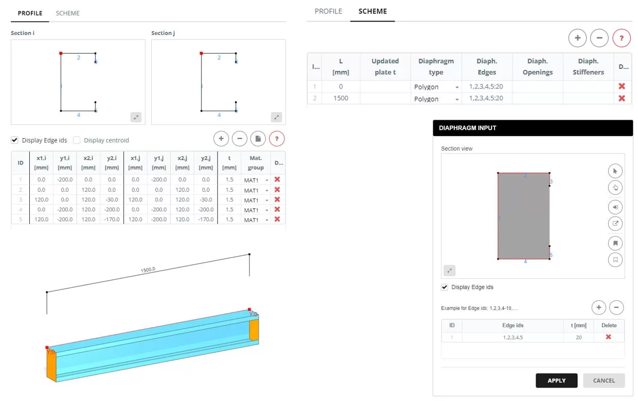
每个成员都有第一部分和一个结尾部分J. 一个部分由由两个节点定义的行组成, X,Y在该部分的飞机上. 每条线都具有独特的厚度t,属于特定材料组. x的参考点,y坐标可以在每个部分中任意选择空间. 每个部分中的行数必须一致. 该表的数据可以手动输入或从Excel表中导入. 另外, 可以从存储在用户PC上的DXF文件中导入部分形状.
更新t: 选定的线组可以更改常见的厚度
更新垫.: 可以为选定的线组更改共同的材料组
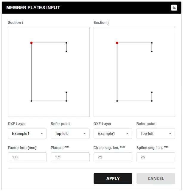
来自DXF的数据.: 从您的PC中选择DXF文件. 选择部分项目的所需层. 参考点确定了 X,和 坐标. 使用该因子扩展部分坐标至毫米. 默认厚度将应用于所有线路, 可以稍后修改. 支持的 DXF 实体包括: 线路, 折线, 弧线, 和样条线. 对于圆弧和样条线, 指定分段划分以匹配首选网格尺寸.
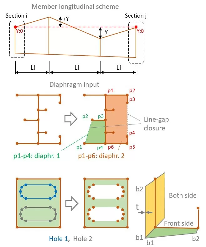
整个构件可以用单个长度 L 或一系列线段 Li 表示. 与段数无关, 起始和结束剖面线将具有与“轮廓”选项卡中定义的相同的坐标. 每个部分还可以有不同的 Y 位置.
对于每个段,其中 大号 不等于 0, 一组板的厚度可以在“更新的板T列”中更新. 通过去 0 隐藏盘子和一个大于 0 修改厚度 (Ť).
对于段部分, 如果“多边形”可以添加膜片’ 选择类型. 指定一个或多个隔膜, 选择组成形状的行. 仅允许一个线间隙封闭形成形状.
孔也可以纳入膜片. 去做这个, 通过选择包含孔的相应线来定义孔形状.
如果指定了隔膜, 然后,也可以通过选择其相关线来定义法兰或加劲台. 每个法兰或加强剂具有起始和结束宽度 (11,b2), 厚度 Ť, 和材料组.
例
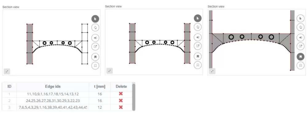
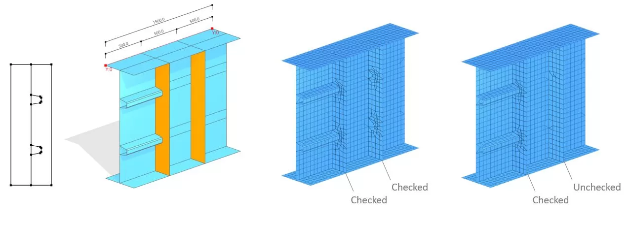
在隔膜内排列边缘时, 他们可以纳入网格划分模式. 例如, 可能会出现纵向加强剂连接到垂直的情况. 在这种情况下, 内部边缘’ 选项应激活. 然而, 如果垂直加强剂未连接到任何东西, 可以停用此选项.