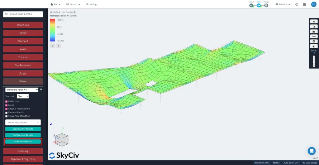
的 板截面切割 工具可以让你提取力量, 片刻, 以及沿着板坯上任何定义的切割线的其他板结果, 盘子, 或墙壁. 这对于板带设计很有用, 检查本地板行为, 并验证负载分布.
如何使用板截面切割工具
解决后, 选择 板块 进而 板截面切割 在左侧面板中.
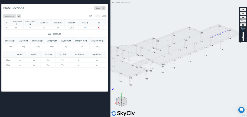
请点击 “添加新剪辑” 创建一个新条目.
每个切口包括:
-
加载组合 – 选择从中提取结果的荷载组合.
-
成分 – 选择结果类型 (例如, Mx, 我的, 尼克斯, 电压, 伍德阿默, 土压力).
-
起始节点 / 终端节点 – 定义要放置剪切的线段.
-
抵消 – 可选择将切割线移动给定距离 (例如,
1,0,0).-
当您希望图表与边缘有一定的偏移量而无需手动计算坐标时,这非常有用.
-
现在你可以画画了 & 运行剪切
按 跑步 生成剪切. 切割线将出现在您的模型上 (如图右侧所示), 和 结果表 将填充每个选定组件的最大值和最小值.
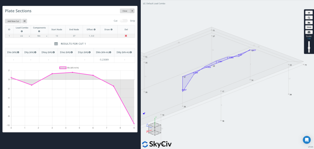
您现在可以绘制图表 直接到几何体上, 沿着切割线直观地显示结果值.
用户还可以通过打开右上角的条带功能来生成条带部分.
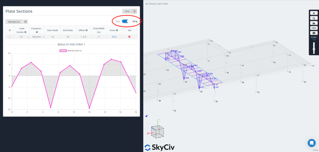
一个 条 提取结果 超过一个宽度, 不只是一条线. 它将在以定义的切割线为中心的有效宽度上平均板材结果 - 这通常用于 板带设计, 设计规范要求对一条板条上的力矩进行平均.
当您需要时,Strip 很有用:
-
单向或双向板带的设计值
-
基于代码的平均 (包括可选的 CSA 三分之二规则)
-
物理条带上比单条线上更具代表性的值