
如果您阅读我们之前的文章, AISC 360: 剪力连接设计, 您将会很好地了解 AISC 下如何设计简单的连接 360. 剪切连接只需提供梁端反作用力. 时刻连接必须传递该反应以及随之而来的结束时刻, 这就带来了支撑柱的问题. 在本文中,我们将研究两个 I 形构件之间的力矩连接示例,并探讨必须满足的设计标准. 我们也可以直接通过 SkyCiv连接设计 模块, 它检查这些连接 AISC 360-16 在 ASD 或 LRFD 中.
如剪力连接示例中所示, 这里的计算使用许用应力设计 (自卫队) 方法. 如果你不熟悉 ASD 和 LRFD 在结构设计上的区别, 确保 看看我们的视频 解释这个.
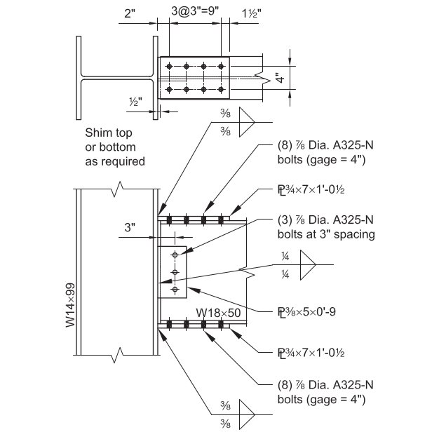
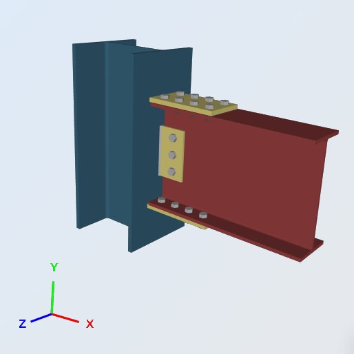
在这个例子中, 我们评估 Bolted 的容量 电镀法兰 完全约束 (阻燃剂) 瞬间连接 在 W18x50 梁和 W14x99 柱之间, 使用尺寸, 焊缝和载荷如下所示. 连接必须支持梁端垂直反作用力和产生的端力矩. 与剪力连接相比, 区别在于一对板将梁翼缘力传递到支撑柱翼缘上.
翼缘板将梁端力矩转化为拉压力偶. 顶板拉动, 底板推动, 两个力以集中力的形式落在柱翼缘上. 这就是为什么弯矩连接需要柱局部检查,而剪力连接则不需要.
给定的:
服务水平负载 & 材料:
静载的垂直剪力 (虚拟机) = 7.0 ps
活荷载的垂直剪力 (VL) = 21.0 ps
静载力矩 (医学博士) = 42.0 基普英尺
来自活荷载的力矩 (机器学习) = 126.0 基普英尺
板材材质: ASTM A36, 风 = 36 KSI, Fu = 58 KSI
梁柱材料: ASTM A992, 风 = 50 KSI, Fu = 65 KSI
梁柱几何:
光束: W18x50; BF = 7.50 在, tf = 0.570 在, d = 18.0 在, tw = 0.355 在, X = 88.9 在^3
柱: W14x99; BF = 14.6 在, tf = 0.780 在, d = 14.2 在, tw = 0.485 在, kdes = 1.38 在
法兰盘: 3/4 在厚; 7.0 在x 12.5 在维度上
腹板: 3/8 在厚; 5.0 在x 9.0 在维度上
灯具 (螺栓和焊缝):
法兰: (8) – 7/8-在.-标准孔中 ASTM F3125 A325-N 级螺栓直径
腹板: (3) – 7/8-在.-标准孔中 ASTM F3125 A325-N 级螺栓直径
70-ksi 电极圆角. A325 和 A490 是 ASTM F3125 范围内的牌号, 整合了旧的独立螺栓规格.
负载计算:
LRFD 负荷 (仅供参考):
终极垂直反应 ([Rü) = 1.2 (7.0 ps) + 1.6 (21.0 ps) = 42.0 ps
终极时刻 (mü) = 1.2 (42.0 基普英尺) + 1.6 (126.0 基普英尺) = 252.0 基普英尺
自卫队 负荷:
允许垂直反应 ([R一个) = 7.0 ps + 21 基普 = 28.0 ps
容许力矩 (m一个) = 42.0 基普英尺 + 126 基普英尺 = 168.0 基普英尺
以下所有内容均根据 ASD 负载进行检查. 将两种方法分开: ASD 将服务负载与允许强度进行比较, LRFD 将因子载荷与设计强度进行比较, 上面的 LRFD 数据只是为了让您可以比较两者.
基于 SkyCiv 连接设计软件的解决方案:
勘误表: 本例中的法兰盘宽度为 7.0 在 但计算中使用的宽度是 7.50 在, 因此价值的差异.
法兰力
接下来的每一项检查都由一个数字驱动, 法兰盘上的力. 最终力矩被解析为作用于板质心的力偶, 所以杠杆臂是梁的深度加上一层板的厚度:
P的 = [ 168.0 基普英尺 (12 英寸/英尺) ] / (18.0 在 + 0.75 在) = 107.5 ps
法兰盘到 W14x99 法兰, 焊接强度
角焊缝强度, Ω = 2.0
焊缝尺寸, t = 0.375 在
F净重 = 0.6 F埃克斯 [ 1.0 + 0.5 没有1.5 (θ) ]
在哪里, θ = 载荷与焊缝轴线的夹角
= 90, 用于横向加载的焊缝
= 0, 用于纵向受力焊缝
单位尺寸焊缝强度:
允许焊接应力, F啊 = 0.6 (70KSI) / 2.0 = 21 KSI
横向长度, 升Ť = 7 在
纵向长度, 升升 = 0 在
总有效长度, 升 = 升Ť (1.5) + 升升 (1.0) = 10.5 在
的 1.5 横向长度上是方向强度增加, 1.0 + 0.5 没有1.5(90).
([R一个 / 一个) = 21 KSI (10.5 在) = 220.5 ps / 在
有效尺寸 (喉) 角焊缝, 一个:
0.707 = 的余弦或正弦 45 度数
a = (0.707) t = 0.265 在
两个焊缝, 盘子的每一面各一个:
[R一个 = ([R一个 / 一个) 一个 (2) = 220.50 (0.265 在) 2 = 116.9 ps
设计容量比, 直流电:
所需负载, R = 107.5 ps
总容量, [R一个 = 116.9 ps
DCR = (107.5 / 116.9) = 0.919, 行
色谱柱局部检查
这四项检查询问 W14x99 是否可以承受法兰力而不产生局部硬化. 所有这些都与相同的法兰力进行比较:
法兰力, P的 = 107.5 ps
- 网络本地收益, Ω = 1.5
[Rñ / Ω = [ F是 Ťw (5ķ + 升b) ] / Ω = 50ksi (0.485在) [ 5(1.38在) + 0.75在 ] / 1.5 = 123.7 ps
这里 Ťw 是柱腹板厚度, 升b 轴承长度, 取法兰板厚度.
设计容量比, 直流电:
法兰力, P的 = 107.5 ps
总容量, [R一个 = 123.7 ps
DCR = (107.5 / 123.7) = 0.869, 行
- 法兰局部弯曲, Ω = 1.67
[Rñ / Ω = [ 6.25 F和 ŤF2 ] / Ω = [ 6.25 (50KSI) (0.78在)2 ] / 1.67 = 113.8 ps
设计容量比, 直流电:
法兰力, P的 = 107.5 ps
总容量, [R一个 = 113.8 ps
DCR = (107.5 / 113.8) = 0.944, 行
- 网络本地瘫痪, Ω = 2.0
[Rñ / Ω = 0.8 Ťw2 [ 1 + 3 ( 升b / d ) ( Ťw / ŤF )1.5 ] ( EF和 ŤF / Ťw)0.5 / Ω
= 0.8 (0.485在)2 [ 1 + 3 (0.05) (0.62)1.5 ] [ (29000KSI) (50KSI) (0.78在) / 0.485在 ] 0.5 / 2.0
= 154.8 ps
设计容量比, 直流电:
法兰力, P的 = 107.5 ps
总容量, [R一个 = 154.8 ps
DCR = (107.5 / 154.8) = 0.694, 行
- 腹板压缩屈曲, Ω = 1.67
[Rñ / Ω = [ 24 Ťw3 ( EF和 )0.5 / H ] / Ω
= 24 (0.485在)3 [ (29000KSI) (50KSI) ] 0.5 / 14.2在 (1.67)
= 139.0 ps
此处使用完整的列深度来代替 H, 法兰之间的净距离减去圆角, 这是保守的.
设计容量比, 直流电:
法兰力, P的 = 107.5 ps
总容量, [R一个 = 139.0 ps
DCR = (107.5 / 139.0) = 0.773, 行
四栏本地检查均不管辖, 因此,对于这些极限状态,W14x99 在没有横向加劲肋的情况下承受法兰力. 其中是否有任何一项超过了 1.0, 修复方法是使用加强筋或双层板,而不是更大的法兰板, 因为用完的容量属于该列.
W18x50 法兰, 法兰盘拉伸屈服
元素抗拉强度, Ω = 1.67
[Rñ / 它们不会带来与矩连接相同的设计挑战和 一个G / Ω = (36KSI) (7.5在) (0.75在) / 1.67 = 121.3 ps
设计容量比, 直流电:
法兰力, P的 = 107.5 ps
总容量, [R一个 = 121.3 ps
DCR = (107.5 / 121.3) = 0.887, 行
W18x50 法兰, 法兰盘压缩屈服
压缩元素的强度, Ω = 1.67
[Rñ / 它们不会带来与矩连接相同的设计挑战和 一个G / Ω = (36KSI) (7.5在) (0.75在) / 1.67 = 121.3 ps
由于螺栓孔被填充在轴承中,因此在总截面上检查压缩板. 它与拉伸屈服值相匹配,因为板在柱面和第一根螺栓线之间足够短,不会降低细长度.
设计容量比, 直流电:
法兰力, P的 = 107.5 ps
总容量, [R一个 = 121.3 ps
DCR = (107.5 / 121.3) = 0.887, 行
W18x50 法兰, 法兰盘拉伸断裂
断裂中的元素强度, Ω = 2.0
剪切滞后因子, ü 来自 AISC 规范表 D3.1: 1.0
[Rñ / 它们不会带来与矩连接相同的设计挑战ü 一个Ë / Ω = (58KSI) [ 7.5在 – 2 (1在) ] (0.75在) (1.0) / 2.0 = 119.6 ps
跨板宽度扣除两个孔. 的 1 推导中就是 7/8 螺栓直径加上 1/8 在, 这是用于净面积的标准孔余量.
设计容量比, 直流电:
法兰力, P的 = 107.5 ps
总容量, [R一个 = 119.6 ps
DCR = (107.5 / 119.6) = 0.899, 行
所有检查结果汇总表
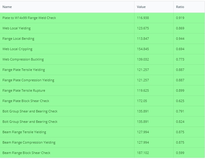
以下是为此连接完成的所有必要设计检查的 SkyCiv 连接设计模块汇总表. 并非所有这些检查都显示在本文中,但可以通过 PDF 获取,您可以在此处下载: 连接设计报告示例 II.B-1-ASD
上述检查中, 法兰局部弯曲控制在 0.944. 这是要观察梁端力矩是否增大的地方, 它是一个列属性, 所以较重的法兰板没有帮助.
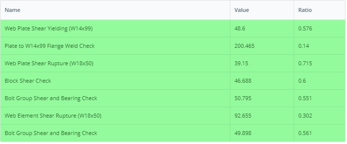
相似地, LRFD 版本示例可以在此链接中找到: 连接设计报告示例 II.B-1-LRFD
自己运行这个例子
输入 W18x50, W14x99 和法兰板, 并且模块返回上面的每个检查及其利用率及其后面的子句. 它在浏览器中运行, 无需安装任何东西.

参考资料
- AISC 360-16, 钢结构建筑规范
- AISC 设计实例 v14.1 (示例 II.B-1, 第IIB-2页到 13)
- SkyCiv连接设计软件: https://skyciv.com/structural-software/connection-design/
- 法兰盘连接计算器: https://skyciv.com/structural-software/connection-design/flange-plate-connection-calculator/
