使用CSA S16的底板设计示例:19 和CSA A23.3:19
问题陈述
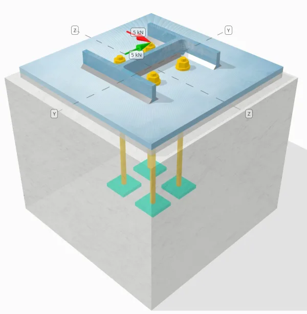
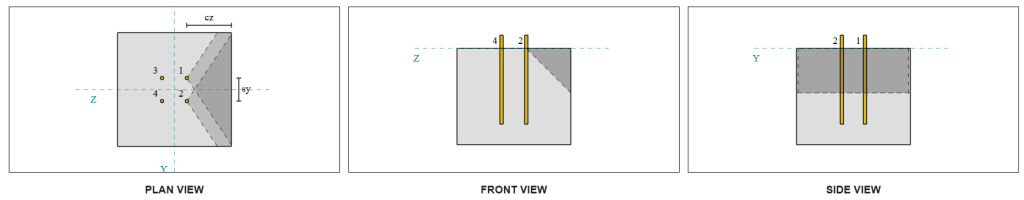
确定设计的列板连接是否足够 您= 5-kn 和 vz = 5-kn 剪力.
给定数据
柱:
列部分: HP200x54
列区域: 6840.0 毫米2
列材料: 350w ^
底盘:
基板尺寸: 400 毫米× 400 毫米
基板厚度: 13 毫米
底板材料: 300w ^
灌浆:
灌浆厚度: 13 毫米
具体:
混凝土尺寸: 450 毫米× 450 毫米
混凝土厚度: 380 毫米
混凝土材料: 20.68 兆帕
破裂或无裂缝: 破裂
锚:
锚直径: 12.7 毫米
有效嵌入长度: 300 毫米
板垫圈厚度: 0 毫米
板垫圈连接: 没有
焊缝:
焊缝尺寸: 8 毫米
填充金属分类: E43xx
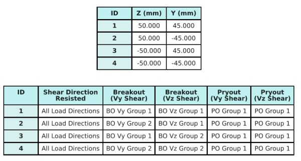
锚数据 (从 SkyCiv计算器):
SkyCiv 免费工具中的模型
立即使用我们的免费在线工具对上面的底板设计进行建模! 无需注册.
定义
负载路径:
设计遵循 CSA A23.3:2019 标准和建议 AISC 设计指南 1, 3RD版. 施加到色谱柱的剪切载荷通过焊缝转移到底板上, 然后通过 锚杆. 在此示例中不考虑摩擦和剪切凸耳, 由于这些机制在当前软件中不支持.
默认, 的 施加的剪切载荷分布到所有锚栓上, 通过使用焊接板垫圈或通过其他工程手段. 每个锚承载的载荷由三个参数确定 (3) 中所述的案例 CSA A23.3:2019 第 D.7.2.1 条和图 D.13. 然后,每个锚将载荷转移到下面的支撑混凝土上. 在检查锚钢抗剪强度时,也使用根据这些参考文献的荷载分布,以确保荷载传递假设的连续性.
作为备选, 该软件允许简化,更保守的假设, 在哪里 整个剪切载荷仅分配给最靠近负载边缘的锚. 在这种情况下, 仅在这些边缘锚点上进行剪切能力检查, 确保保守解决潜在的剪切故障.
锚群:
的 SkyCiv 底板设计软件 包括一个直观的功能,该功能标识哪些锚定为评估的锚点组的一部分 混凝土剪切突破 和 具体的剪切撬 失败.
一个 锚群 被定义为两个或多个锚,并具有重叠的预防阻力区域. 在这种情况下, 锚一起行动, 并且它们的组合电阻被检查针对该组的施加载荷.
一个 单锚 被定义为锚点,其投影阻力区域不会与其他任何. 在这种情况下, 锚独自行动, 并直接检查锚上施加的剪切力,以其单独的电阻检查.
在评估剪切相关的故障模式时.
分步计算
检查一下 #1: 计算焊接容量
第一步是计算 总焊接长度 可抵抗剪切. 焊缝总长度, 焊接, 通过对所有侧面的焊缝求和获得.
\( L_{焊接} = 2b_f + 2(d_{上校} – 2T_F – 2r_{上校}) + 2(B_F – t_w – 2r_{上校}) \)
\( L_{焊接} = 2 \次 207,text{毫米} + 2 \次 (204,\文本{毫米} – 2 \乘以 11.3,text{毫米} – 2 \乘以 9.7,text{毫米}) + 2 \次 (207,\文本{毫米} – 11.3,\文本{毫米} – 2 \乘以 9.7,text{毫米}) = 1090.6,文本{毫米} \)
使用此焊接长度, Y中的施加力- 和z方向分配以确定平均值 单位长度的剪切力 在每个方向:
\( v_{风云} = frac{v_y}{L_{焊接}} = frac{5,\文本{千牛}}{1090.6,\文本{毫米}} = 0.0045846,文本{千牛/毫米} \)
\( v_{弗兹} = frac{v_z}{L_{焊接}} = frac{5,\文本{千牛}}{1090.6,\文本{毫米}} = 0.0045846,文本{千牛/毫米} \)
的 合成剪切需求 然后使用平方和的平方根确定每单位长度 (SRSS) 方法.
\( v_f = sqrt{\剩下((v_{风云})^2右) + \剩下((v_{弗兹})^2右)} \)
\( v_f = sqrt{\剩下((0.0045846,\文本{千牛/毫米})^2右) + \剩下((0.0045846,\文本{千牛/毫米})^2右)} = 0.0064836,文本{千牛/毫米} \)
下一个, 焊接容量是使用 CSA S16:19 条款 13.13.2.2, 将定向强度系数视为 kds=1.0 保守一点. 翼缘和腹板上 8mm 焊缝的焊接能力为:
\( v_r = 0.67phi t_{w,法兰}X_u = 0.67 \次 0.67 \乘以 5.657,text{毫米} \乘以 430,文本{兆帕} = 1.092,文本{千牛/毫米} \)
\( v_r = 0.67phi t_{w,普拉特桁架和普拉特桁架设计的技术研究}X_u = 0.67 \次 0.67 \乘以 5.657,text{毫米} \乘以 430,文本{兆帕} = 1.092,文本{千牛/毫米} \)
执政者 角焊缝产能 是:
\( v_{[R,鱼片} = min(v_r, v_i) = min(1.092\,\文本{千牛/毫米}, 1.092\,\文本{千牛/毫米}) = 1.092,文本{千牛/毫米} \)
对于这种焊接连接, 电极强度 没有超越 贱金属的强度. 因此, 基底金属检查不具有控制作用,不需要执行.
以来 0.0064 千牛/毫米 < 1.092 千牛/毫米, 焊接能力系数为 充足的.
检查一下 #2: 计算由于Vy剪切的混凝土突破能力
垂直边缘容量:
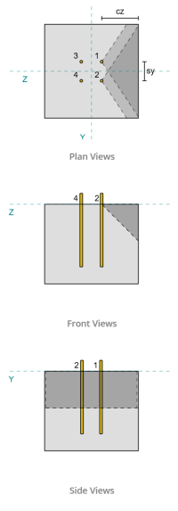
使用每个锚点的 ca1 值来投影失效锥体, 软件发现这些锚的失效锥体重叠. 因此, 我们可以将它们视为 锚群. 参考 CSA A23.3:19 图. D.13, 因为是<ca1, 我们用 案件 3 确定锚固组抗剪切破坏的阻力. 此外, 支持已确定 不是 成为一个狭隘的成员, 所以直接使用ca1距离,无需修改.
案件 3:
案例要考虑的总力 3 是个 全剪切力 沿Vy方向. 该剪切力仅作用于前锚.
\( V_{fa perp,案例3} = V_y = 5,文本{千牛} \)
计算锚定组的容量, 我们用 CSA A23.3:19 第 D.7.2 条. 的 最大投影面积 对于单个锚点的计算方法是 公式 D.34 与实际的 ca 尺寸.
\( 一个_{压控振荡器} = 4.5(C_{a1、g1})可以假设为 4.5 \次 (180\,\文本{毫米})^2 = 145800,文本{毫米}^ 2 \)
获取锚点组的实际投影面积, 我们首先确定 破坏面宽度:
\( b_{VC} = min(C_{\文本{剩下},G1}, 1.5C_{a1、g1}) + (\分(s_{\文本{和},X,G1}, 3C_{a1、g1}(n_{X,G1} – 1))) + \分(C_{\文本{对},G1}, 1.5C_{a1、g1}) \)
\( b_{VC} = min(175\,\文本{毫米}, 1.5 \乘以 180,文本{毫米}) + (\分(100\,\文本{毫米}, 3 \乘以 180,文本{毫米} \次 (2-1))) + \分(175\,\文本{毫米}, 1.5 \乘以 180,文本{毫米}) \)
\( b_{VC} = 450,文本{毫米} \)
的 破坏面高度 是:
\( H_{VC} = min(1.5C_{a1、g1}, t_{\文本{浓}}) = min(1.5 \乘以 180,文本{毫米}, 380\,\文本{毫米}) = 270,文本{毫米} \)
这给了 总面积 作为:
\( 一个_{VC} = b_{VC}.H_{VC} = 450,文本{毫米} \乘以 270,文本{毫米} = 121500,文本{毫米}^ 2 \)
然后我们使用 CSA A23.3:19 方程 D.35 和 D.36 获得基本的单锚突破强度.
\( V_{br1} = 0.58左(\压裂{\分(这, 8D_A)}{D_A}\对)^{0.2}\sqrt{\压裂{D_A}{毫米}}\philambda_asqrt{\压裂{f'_c}{兆帕}}\剩下(\压裂{C_{a1、g1}}{毫米}\对)^{1.5}[R(ñ) \)
\( V_{br1} = 0.58 \时代左(\压裂{\分(300\,\文本{毫米}, 8 \乘以 12.7,text{毫米})}{12.7\,\文本{毫米}}\对)^{0.2} \次 sqrt{\压裂{12.7\,\文本{毫米}}{1\,\文本{毫米}}} \次 0.65 \次 1 \次 sqrt{\压裂{20.68\,\文本{兆帕}}{1\,\文本{兆帕}}} \时代左(\压裂{180\,\文本{毫米}}{1\,\文本{毫米}}\对)^{1.5} \次 1 \次0.001 , text{千牛} \)
\( V_{br1} = 22.364,文本{千牛} \)
\( V_{br2} = 3.75lambda_aphisqrt{\压裂{f'_c}{兆帕}}\剩下(\压裂{C_{a1、g1}}{毫米}\对)^{1.5}[R(ñ) \)
\( V_{br2} = 3.75 \次 1 \次 0.65 \次 sqrt{\压裂{20.68\,\文本{兆帕}}{1\,\文本{兆帕}}} \时代左(\压裂{180\,\文本{毫米}}{1\,\文本{毫米}}\对)^{1.5} \次 1 \次0.001 , text{千牛} = 26.769,文本{千牛} \)
两种条件之间的治理能力为:
\( V_{br} = min(V_{\文本{br1}}, V_{\文本{br2}}) = min(22.364\,\文本{千牛}, 26.769\,\文本{千牛}) = 22.364,文本{千牛} \)
下一个, 我们计算偏心系数, 边缘效应因子, 和厚度系数使用 CSA A23.3:19 条款 D.7.2.5, D.7.2.6, 和 D.7.2.8.
的 偏心率因子 是:
\( \psi_{欧共体,V} = min 左(1.0, \压裂{1}{1 + \压裂{2和’_N}{3C_{a1、g1}}}\对) = min 左(1, \压裂{1}{1 + \压裂{2\次0}{3\times180,文本{毫米}}}\对) = 1 \)
的 边缘效应因子 是:
\( \psi_{编辑,V} = min 左(1.0, 0.7 + 0.3\剩下(\压裂{C_{a2,g1}}{1.5C_{a1、g1}}\对)\对) = min 左(1, 0.7 + 0.3 \时代左(\压裂{175\,\文本{毫米}}{1.5 \乘以 180,文本{毫米}}\对)\对) = 0.89444 \)
的 厚度因子 是:
\( \psi_{H,V} = max left(\sqrt{\压裂{1.5C_{a1、g1}}{t_{\文本{浓}}}}, 1.0\对) = max left(\sqrt{\压裂{1.5 \乘以 180,文本{毫米}}{380\,\文本{毫米}}}, 1\对) = 1 \)
最后, 锚固组的突破强度, 计算使用 CSA A23.3:19 第 D.7.2.1 条, 是:
\( V_{CBGperp} = 左(\压裂{一个_{VC}}{一个_{压控振荡器}}\对)\psi_{欧共体,V}\psi_{编辑,V}\psi_{C,V}\psi_{H,V}V_{br} \)
\( V_{CBGperp} = 左(\压裂{121500\,\文本{毫米}^ 2}{145800\,\文本{毫米}^ 2}\对) \次 1 \次 0.89444 \次 1 \次 1 \乘以 22.364,text{千牛} = 16.669,文本{千牛} \)
计算出的 Vy 剪切能力 垂直方向 是 16.669 千牛.
平行边缘容量:
沿途失败 边缘平行于负载 在这种情况下也是可能的, 因此必须确定平行边缘的混凝土破断能力. 由于新的失效锥投影,涉及的锚有所不同. 基于下图, 的 失效锥投影重叠; 因此, 锚点再次被视为 锚群.
案件 3:
使用的案例仍然是 案件 3 自从 s<ca1. 因此, 该锚固组承受的荷载为 满 Vy 剪切载荷.
\( V_{fa perp,案例3} = V_y = 5,文本{千牛} \)
然后我们跟随 相同的步骤 至于垂直能力.
失效面为 个人锚 是:
\( 一个_{压控振荡器} = 4.5(C_{a1、g1})可以假设为 4.5 \次 (175\,\文本{毫米})^2 = 137810,文本{毫米}^ 2 \)
的 实际破坏面 锚群是:
\( b_{VC} = min(C_{\文本{底部},G1}, 1.5C_{a1、g1}) + (\分(s_{\文本{和},和,G1}, 3C_{a1、g1}(n_{和,G1} – 1))) + \分(C_{\文本{最佳},G1}, 1.5C_{a1、g1}) \)
\( b_{VC} = min(180\,\文本{毫米}, 1.5 \乘以 175,文本{毫米}) + (\分(90\,\文本{毫米}, 3 \乘以 175,文本{毫米} \次 (2-1))) + \分(180\,\文本{毫米}, 1.5 \乘以 175,文本{毫米}) \)
\( b_{VC} = 450,文本{毫米} \)
\( H_{VC} = min(1.5C_{a1、g1}, t_{\文本{浓}}) = min(1.5 \乘以 175,文本{毫米}, 380\,\文本{毫米}) = 262.5,文本{毫米} \)
\( 一个_{VC} = b_{VC}H_{VC} = 450,文本{毫米} \乘以262.5,文本{毫米} = 118130,文本{毫米}^ 2 \)
相似地, 的 基本单锚突破 优势 计算如下:
\( V_{br1} = 0.58左(\压裂{\分(这, 8D_A)}{D_A}\对)^{0.2}\sqrt{\压裂{D_A}{毫米}}\philambda_asqrt{\压裂{f'_c}{兆帕}}\剩下(\压裂{C_{a1、g1}}{毫米}\对)^{1.5}[R(ñ) \)
\( V_{br1} = 0.58 \时代左(\压裂{\分(300\,\文本{毫米}, 8 \乘以 12.7,text{毫米})}{12.7\,\文本{毫米}}\对)^{0.2} \次 sqrt{\压裂{12.7\,\文本{毫米}}{1\,\文本{毫米}}} \次 0.65 \次 1 \次 sqrt{\压裂{20.68\,\文本{兆帕}}{1\,\文本{兆帕}}} \时代左(\压裂{175\,\文本{毫米}}{1\,\文本{毫米}}\对)^{1.5} \次 1 \次0.001 , text{千牛} \)
\( V_{br1} = 21.438,文本{千牛} \)
\( V_{br2} = 3.75lambda_aphisqrt{\压裂{f'_c}{兆帕}}\剩下(\压裂{C_{a1、g1}}{毫米}\对)^{1.5}[R(ñ) \)
\( V_{br2} = 3.75 \次 1 \次 0.65 \次 sqrt{\压裂{20.68\,\文本{兆帕}}{1\,\文本{兆帕}}} \时代左(\压裂{175\,\文本{毫米}}{1\,\文本{毫米}}\对)^{1.5} \次 1 \次0.001 , text{千牛} = 25.661,文本{千牛} \)
的 执政实力 是:
\( V_{br} = min(V_{\文本{br1}}, V_{\文本{br2}}) = min(21.438\,\文本{千牛}, 25.661\,\文本{千牛}) = 21.438,文本{千牛} \)
然后我们计算 偏心率因子 和 厚度因子:
\( \psi_{欧共体,V} = min 左(1.0, \压裂{1}{1 + \压裂{2和’_N}{3C_{a1、g1}}}\对) = min 左(1, \压裂{1}{1 + \压裂{2\次0}{3\times175,文本{毫米}}}\对) = 1 \)
\( \psi_{H,V} = max left(\sqrt{\压裂{1.5C_{a1、g1}}{t_{\文本{浓}}}}, 1.0\对) = max left(\sqrt{\压裂{1.5 \乘以 175,文本{毫米}}{380\,\文本{毫米}}}, 1\对) = 1 \)
为了 突破边缘效应因子, 我们把它当作 1.0 适用于 CSA A23.3:19 条款 D.7.2.1c. 此外, 垂直边缘的分断能力值取为 使用公式 D.33 计算得出的值的两倍 (对于锚定组).
的 归纳 锚固组的突破能力 是:
\( V_{cbgr并行} = 2左(\压裂{一个_{VC}}{一个_{压控振荡器}}\对)\psi_{欧共体,V}\psi_{编辑,V}\psi_{C,V}\psi_{H,V}V_{br} \)
\( V_{cbgr并行} = 2 \时代左(\压裂{118130\,\文本{毫米}^ 2}{137810\,\文本{毫米}^ 2}\对) \次 1 \次 1 \次 1 \次 1 \乘以 21.438,text{千牛} = 36.752,文本{千牛} \)
- 为了 垂直边 失败, 以来 5 千牛 < 16.7 千牛, 混凝土剪切突破能力是 充足的.
- 为了 平行边 失败, 以来 5 千牛 < 36.8 千牛, 混凝土剪切突破能力是 充足的.
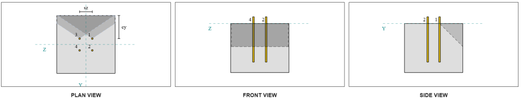
计算由于VZ剪切而导致的混凝土突破能力
底板也受到 Vz 剪切, 所以故障边缘 垂直和平行于 Vz 剪切力 必须检查. 使用相同的方法, 垂直和平行容量计算为 16.6 千牛和 37.3 千牛, 分别.
垂直边缘:
平行边缘:
然后将这些能力与所需的优势进行比较.
- 为了 垂直边 失败, 以来 5 千牛 < 16.6 千牛, 预制混凝土的剪切破坏能力为 充足的.
- 为了 平行边缘失效, 以来 5 千牛 < 37.3 千牛, 预制混凝土的剪切破坏能力为 充足的.
检查一下 #4: 计算具体的撬动能力
混凝土锥体用于 撬出失败 与中使用的锥体相同 拉伸断裂检查. 计算剪切撬能的能力, 的 标称拉伸突破强度 必须首先确定单个锚点或锚点组. 拉伸断裂检查的详细计算已包含在 张力负载的SkyCiv设计示例 这里不再重复.
需要注意的是,剪切破坏的锚固组确定与剪切撬出的锚固组确定不同. 仍然必须检查设计中的锚点以确定它们是否 作为一个团体或作为一个单一的锚. 的分类 作为狭窄部分的支撑 还必须进行验证,并应遵循用于张力突破的相同条件.
根据SkyCiv软件, 锚固组的标称拉伸断裂强度为 60.207 千牛. 撬动因素 2.0, 的 因子撬出能力 是:
\( V_{CPGR} 检查锚容量{cp}N_{CBR} = 2 \乘以 60.207,text{千牛} = 120.41,文本{千牛} \)
所需的强度是 结果 所施加的剪切载荷. 由于所有锚都属于一个组, 将总剪切分配给组.
\( V_{fa} = sqrt{((v_y)^ 2) + ((v_z)^ 2)} = sqrt{((5\,\文本{千牛})^ 2) + ((5\,\文本{千牛})^ 2)} = 7.0711,文本{千牛} \)
\( V_{fa} = 左(\压裂{V_{fa}}{N_A}\对)n_{一个,G1} = 左(\压裂{7.0711\,\文本{千牛}}{4}\对) \次 4 = 7.0711,文本{千牛} \)
以来 7.07 千牛 < 120.4 千牛, 因子化的 pryout 容量为 充足的.
检查一下 #5: 计算锚杆剪切能力
回想一下这个设计示例, 剪切分配给所有锚. 的 每个锚的总剪切载荷 因此是其 Vy 负载份额和 Vz 负载份额的结果. 我们还考虑 管辖案件 用于剪切断裂检查.
对于Vy剪切, 案件 3 正在统治.
\( V_{fa,和} = frac{v_y}{n_{与,G1}} = frac{5\,\文本{千牛}}{2} = 2.5,文本{千牛} \)
相似地, 对于 Vz 剪切, 案件 3 正在统治.
\( V_{fa,与} = frac{v_z}{n_{和,G1}} = frac{5\,\文本{千牛}}{2} = 2.5,文本{千牛} \)
这给了 锚杆上的剪力 作为:
\( V_{fa} = sqrt{((V_{fa,和})^ 2) + ((V_{fa,与})^ 2)} = sqrt{((2.5\,\文本{千牛})^ 2) + ((2.5\,\文本{千牛})^ 2)} = 3.5355,文本{千牛} \)
在这个设计实例中, 存在灌浆. 因此, 锚杆也经历 由于偏心剪切而弯曲. 考虑到这一点, 我们可以应用 灌浆减少系数符合 CSA A23.3:19 第 D.7.1.3 条 要么 使用 CSA S16 检查剪切-弯曲相互作用:19 条款 13.12.1.4.
为此计算, 我们选择使用 0.8 减少 来自 CSA A23.3 的因素. 允许个人工程判断, 的 SkyCiv底板软件 提供禁用此缩减因子并改为使用剪切-弯曲相互作用检查的选项. 可以使用以下方法探索此功能 底板免费工具.
CSA A23.3 锚杆抗剪能力:
第一, 我们使用 CSA A23.3 计算锚杆抗剪能力. 的 最小拉应力 锚杆的:
\( F_{乌塔} = min(F_{u _anc}, 1.9F_{第一个}, 860) = min(400\,\文本{兆帕}, 1.9 \乘以 248.2,text{兆帕}, 860.00\,\文本{兆帕}) = 400,文本{兆帕} \)
的 锚杆抗剪承载力系数, 计算使用 CSA A23.3:19 公式 D.31 和条款 D.7.1.3, 是:
\( V_{sar,a23} = 0.8A_{我知道,V}\phi_s0.6f_{乌塔}R = 0.8 \乘以 92,文本{毫米}^2 times 0.85 \次 0.6 \乘以 400,文本{兆帕} \次 0.75 = 11.258,文本{千牛} \)
请注意, 0.8 由于存在灌浆,此处应用折减系数. 这种降低的剪切能力导致了锚杆的额外弯曲.
CSA S16 锚杆抗剪能力:
对于 CSA S16 容量, 只有 检查剪切能力d, 因为偏心剪切引起的弯曲已在 CSA A23.3 检查中考虑在内.
的 因数剪切能力 计算使用 CSA S16:19 条款 25.3.3.3.
\( V_{[R,s16} = 0.7phi_m 0.6n A_{高级} F_{u _anc} = 0.7 \次 0.67 \次 0.6 \次 1 \乘以 126.68,文本{毫米}^2 乘以400 ,文本{兆帕} = 14.255,文本{千牛} \)
确保两种方法都得到考虑, 治理能力取两个值中较小的一个, 这是 11.258 千牛.
以来 3.54 千牛 < 11.258 千牛, 锚杆抗剪承载力系数为 充足的.
设计概要
的 SkyCiv底板设计软件 可以自动为此设计示例生成逐步计算报告. 它还提供了执行的检查及其结果比率的摘要, 一目了然地使信息易于理解. 以下是示例摘要表, 报告中包括.
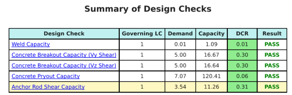
SkyCiv样本报告
查看 SkyCiv 底板设计报告的详细程度和清晰度. 该报告包括所有关键的设计检查, 方程式, 并以清晰易读的格式呈现结果. 完全符合设计标准. 单击下面查看使用 SkyCiv 底板计算器生成的示例报告.
购买基板软件
单独购买基本板设计模块的完整版本,而没有任何其他SkyCiv模块. 这为您提供了底板设计的完整结果, 包括详细报告和更多功能.