基本板设计示例使用AISC 360-22 和ACI 318-19
问题陈述
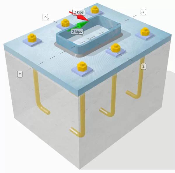
确定设计的列板连接是否足够 vy = 2 kip 和 VZ = 2鸡 剪力.
给定数据
柱:
列部分: HSS7x4x5/16
列区域: 7.59 在2
列材料: A36
底盘:
基板尺寸: 12 在x 14 在
基板厚度: 3/4 在
底板材料: A36
灌浆:
灌浆厚度: 0.25 在
具体:
混凝土尺寸: 12 在x 14 在
混凝土厚度: 10 在
混凝土材料: 3000 压力
破裂或无裂缝: 破裂
锚:
锚直径: 1/2 在
有效嵌入长度: 8 在
板垫圈厚度: 0.25 在
板垫圈连接: 焊接到底板
焊缝:
焊缝尺寸: 1/4 在
填充金属分类: E70XX
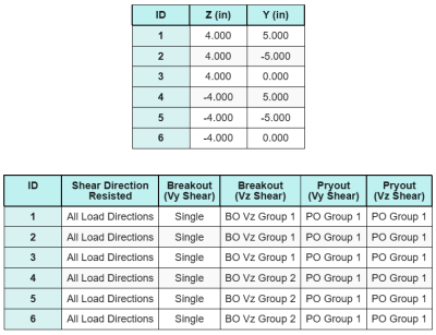
锚数据 (从 SkyCiv计算器):
SkyCiv 免费工具中的模型
立即使用我们的免费在线工具对上面的底板设计进行建模! 无需注册.
定义
负载路径:
该设计遵循的建议 AISC 设计指南 1, 3RD版, 和ACI 318-19. 施加到色谱柱的剪切载荷通过焊缝转移到底板上, 然后通过 锚杆. 在此示例中不考虑摩擦和剪切凸耳, 由于这些机制在当前软件中不支持.
默认, 应用 剪切载荷分布到所有锚栓上, 通过使用焊接板垫圈或通过其他工程手段. 每个锚承载的载荷由三个参数确定 (3) 中所述的案例 ACI 318-19 条款 17.7.2 和图. R17.7.2.1b. 然后,每个锚将载荷转移到下面的支撑混凝土上. 在检查锚钢抗剪强度时,也使用根据这些参考文献的荷载分布,以确保荷载传递假设的连续性.
作为备选, 该软件允许简化,更保守的假设, 整个剪切负荷仅分配给 锚定最近的边缘. 在这种情况下, 仅在这些边缘锚点上进行剪切能力检查.
锚群:
的 SkyCiv 底板设计软件 包括一个直观的功能,该功能标识哪些锚定为评估的锚点组的一部分 混凝土剪切突破 和 具体的剪切撬 失败.
一个 锚群 被定义为两个或多个锚,并具有重叠的预防阻力区域. 在这种情况下, 锚一起行动, 并且它们的组合电阻被检查针对该组的施加载荷.
一个 单锚 被定义为锚点,其投影阻力区域不会与其他任何. 在这种情况下, 锚独自行动, 并直接检查锚上施加的剪切力,以其单独的电阻检查.
在评估剪切相关的故障模式时.
分步计算
检查一下 #1: 计算焊接容量
第一步是计算 总焊接长度 可抵抗剪切. 由于底板沿着色谱柱的周长焊接, 总焊接长度是通过将各个方面的焊接求和来获得的.
\( L_{焊接} = 2 \剩下( b_{上校} – 2r_{上校} – 2t_{上校} \对) + 2 \剩下( d_{上校} – 2r_{上校} – 2t_{上校} \对) \)
\( L_{焊接} = 2 \次 (4\,\文本{在} – 2 \时间0.291 , text{在} – 2 \时间0.291 , text{在}) + 2 \次 (7\,\文本{在} – 2 \时间0.291 , text{在} – 2 \时间0.291 , text{在}) = 17.344 , text{在} \)
使用此焊接长度, Y中的施加力- 和z方向分配以确定平均值 单位长度的剪切力 在每个方向:
\( v_{你} = frac{v_y}{L_{焊接}} = frac{2\,\文本{基普}}{17.344\,\文本{在}} = 0.11531 , text{kip/in} \)
\( v_{到} = frac{v_z}{L_{焊接}} = frac{2\,\文本{基普}}{17.344\,\文本{在}} = 0.11531 , text{kip/in} \)
的 结果剪切 单位长度的需求 然后使用正方形之和的平方根确定 (SRSS) 方法.
\( r_u = sqrt{(v_{你})^ 2 + (v_{到})^ 2} \)
\( r_u = sqrt{(0.11531\,\文本{kip/in})^ 2 + (0.11531\,\文本{kip/in})^ 2} = 0.16308 , text{kip/in} \)
下一个, 焊接容量是使用 AISC 360-22 情商. J2-4, 将定向强度系数视为 KDS = 1.0 对于HSS部分. 焊接能力 1/4 在焊缝中被确定为:
\( \phi r_n = phi 0.6 F_{EXX} e_w k_{DS} = 0.75 \次 0.6 \时代70 , text{KSI} \时间0.177 , text{在} \次 1 = 5.5755 , text{kip/in} \)
还必须检查碱金属, 圆柱和底板, 使用 AISC 360-22 情商. J4-4 获得剪切破裂强度. 这给了:
\( \phi r_{NBM, 上校} = phi 0.6 F_{u _col} t_{上校} = 0.75 \次 0.6 \时58 , text{KSI} \时间0.291 , text{在} = 7.5951 , text{kip/in} \)
\( \phi r_{NBM, BP} = phi 0.6 F_{u _bp} t_{BP} = 0.75 \次 0.6 \时58 , text{KSI} \时间0.75 , text{在} = 19.575 , text{kip/in} \)
\( \phi r_{NBM} = min 左( \phi r_{NBM, BP},\, \phi r_{NBM, 上校} \对) = min(19.575\,\文本{kip/in},\, 7.5951\,\文本{kip/in}) = 7.5951 , text{kip/in} \)
由于实际的焊接应力小于焊接金属和碱金属能力, 0.16308 KPI < 5.5755 kpi和 0.16308 KPI < 7.5951 KPI, 设计焊接容量是 充足的.
检查一下 #2: 计算由于Vy剪切的混凝土突破能力
垂直边缘容量:
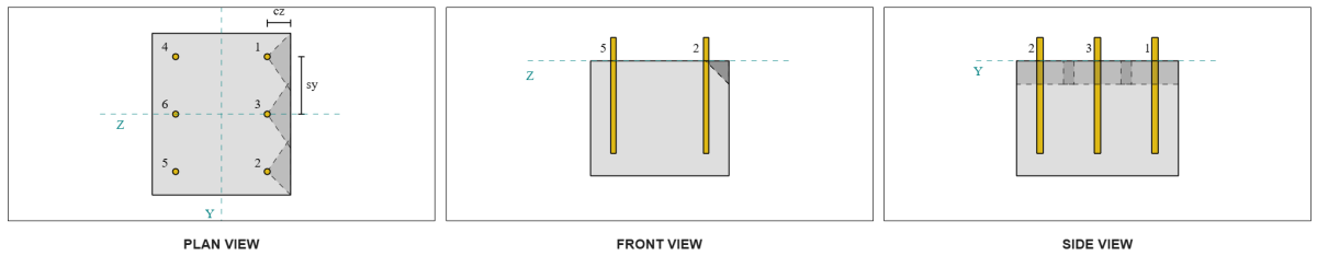
从布局, 锚 1 和 4 最接近边缘,有 最短的CA1距离. 使用这些CA1值投影故障锥, 该软件将这些锚定为 单锚, 由于他们的投影锥不会重叠. 支持还确定不是狭窄的成员, 因此CA1距离无需修改即可直接使用.
让我们回想一下,假定剪切力分布在所有锚点中. 计算 VY剪切负荷 应用于每个锚是:
\( V_{fa perp} = frac{v_y}{N_A} = frac{2\,\文本{基普}}{6} = 0.33333 , text{基普} \)
让我们考虑一下 锚 1. 单个锚的最大投影区域是使用 ACI 318-19 情商. 17.7.2.1.3.
\( 一个_{压控振荡器} = 4.5 (C_{A1,S1})可以假设为 4.5 \次 (2\,\文本{在})^2 = 18 , text{在}^ 2 \)
然后从预计故障锥的宽度和高度确定实际投影区域.
\( b_{VC} = min(C_{剩下,s1},\, 1.5C_{A1,S1}) + \分(C_{对,s1},\, 1.5C_{A1,S1}) \)
\( b_{VC} = min(10\,\文本{在},\, 1.5 \时2 , text{在}) + \分(2\,\文本{在},\, 1.5 \时2 , text{在}) = 5 , text{在} \)
\( H_{VC} = min(1.5C_{A1,S1},\, t_{浓}) = min(1.5 \时2 , text{在},\, 10\,\文本{在}) = 3 , text{在} \)
\( 一个_{VC} = b_{VC} H_{VC} = 5 , text{在} \时间3 , text{在} = 15 , text{在}^ 2 \)
下一步是使用 等式17.7.2.2.1a和17.7.2.2.1b 计算单个锚的基本突破强度. 理事能力被视为较小的价值.
\( V_{11} = 7 \剩下( \压裂{\分(这,\, 8D_A)}{D_A} \对)^{0.2} \sqrt{\压裂{D_A}{\文本{在}}} \lambda_a sqrt{\压裂{f'_c}{\文本{压力}}} \剩下( \压裂{C_{A1,S1}}{\文本{在}} \对)^{1.5} \,\文本{磅力} \)
\( V_{11} = 7 \时代左( \压裂{\分(8\,\文本{在},\, 8 \时间0.5 , text{在})}{0.5\,\文本{在}} \对)^{0.2} \次 sqrt{\压裂{0.5\,\文本{在}}{1\,\文本{在}}} \次 1 \次 sqrt{\压裂{3\,\文本{KSI}}{0.001\,\文本{KSI}}} \时代左( \压裂{2\,\文本{在}}{1\,\文本{在}} \对)^{1.5} \次0.001 , text{基普} \)
\( V_{11} = 1.1623 , text{基普} \)
\( V_{b2} = 9 \lambda_a sqrt{\压裂{f'_c}{\文本{压力}}} \剩下( \压裂{C_{A1,S1}}{\文本{在}} \对)^{1.5} \,\文本{磅力} \)
\( V_{b2} = 9 \次 1 \次 sqrt{\压裂{3\,\文本{KSI}}{0.001\,\文本{KSI}}} \时代左( \压裂{2\,\文本{在}}{1\,\文本{在}} \对)^{1.5} \次0.001 , text{基普} = 1.3943 , text{基普} \)
\( v_b = min(V_{11},\, V_{b2}) = min(1.1623\,\文本{基普},\, 1.3943\,\文本{基普}) = 1.1623 , text{基普} \)
下一个, 的 突破容量参数 确定. 的 突破边缘效应因子 根据 ACI 318-19 条款 17.7.2.4, 和 厚度因子 根据 条款 17.7.2.6.1.
\( \psi_{编辑,V} = min 左(1.0,\, 0.7 + 0.3 \剩下( \压裂{C_{A2,S1}}{1.5C_{A1,S1}} \对) \对) = min 左(1,\, 0.7 + 0.3 \时代左( \压裂{2\,\文本{在}}{1.5 \时2 , text{在}} \对) \对) = 0.9 \)
\( \psi_{H,V} = max left( \sqrt{ \压裂{1.5C_{A1,S1}}{t_{浓}} },\, 1.0 \对) = max left( \sqrt{ \压裂{1.5 \时2 , text{在}}{10\,\文本{在}} },\, 1 \对) = 1 \)
最后, ACI 318-19 条款 17.7.2.1(一个) 用于确定剪切中单个锚的混凝土突破能力. 垂直方向上VY剪切的计算能力为 0.69 ps.
\( \非V_{CB perp} = phi 左( \压裂{一个_{VC}}{一个_{压控振荡器}} \对) \psi_{编辑,V} \psi_{C,V} \psi_{H,V} v_b \)
\( \非V_{CB perp} = 0.65 \时代左( \压裂{15\,\文本{在}^ 2}{18\,\文本{在}^ 2} \对) \次 0.86 \次 1 \次 1 \次1.1623 , text{基普} = 0.56661 , text{基普} \)
计算的能力 vy剪 在里面 垂直 方向是 0.56 ps.
平行边缘容量:
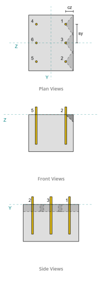
在这种情况下,沿着与负载平行的边缘失败也可能, 所以 平行边缘的混凝土突破能力 必须确定. 所考虑的锚或锚组是与平行边缘对齐的锚. 所以, 的 CA1 边缘距离从锚沿z方向测量到边缘. 基于下图, 故障锥投影重叠; 因此, 锚被视为一组.
案件 1:
案件 2:
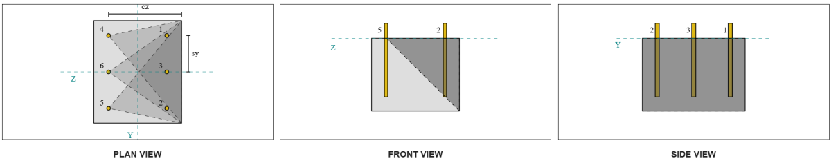
我们指的是 ACI 318-19 图. R17.7.2.1b 对于评估锚组时使用的不同情况. 在这个底板设计中, 焊接板垫圈 专门使用. 因此, 只要 案件 2 被检查.
锚组所需的负载,以防万一 2 被视为 总剪切负荷.
\( V_{fa 平行,案例2} = v_y = 2 , text{基普} \)
在计算案件的能力时 2 失败, 考虑的锚是 后锚. 结果是, CA1边缘距离从后锚组到故障边缘测量.
使用CA1距离和边缘方向, 必须验证支持是否符合狭窄成员的资格. 下列的 ACI 318-19 条款 17.7.2.1.2, SkyCiv基板软件将支持确定为 狭窄的. 因此, 的 修改的CA1距离 用来, 计算为 6.667 在.
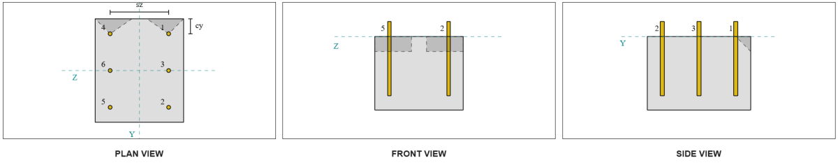
与垂直案例相同的步骤: 计算 预计故障区域, 的 基本的单杆突破强度, 和 突破参数. 每个步骤的计算值如下所示.
\( 一个_{压控振荡器} = 4.5 (C_{‘A1,G2})可以假设为 4.5 \次 (6.6667\,\文本{在})^2 = 200 , text{在}^ 2 \)
\( 一个_{VC} = b_{VC} H_{VC} = 14 , text{在} \时间10 , text{在} = 140 , text{在}^ 2 \)
\( V_{11} = 7.0733 , text{基普} \)
\( V_{b2} = 8.4853 , text{基普} \)
\( v_b = min(V_{11},\, V_{b2}) = min(7.0733\,\文本{基普},\, 8.4853\,\文本{基普}) = 7.0733 , text{基普} \)
\( \psi_{编辑,V} = 1.0 \)
\( \psi_{H,V} = 1.0 \)
平行边缘容量的方程与垂直边缘容量不同. ACI 318-19 条款 17.7.2.1(C) 应用, 突破方程在哪里 乘以 2.
\( \非V_{CBG parallel} = 2 \phi 左( \压裂{一个_{VC}}{一个_{压控振荡器}} \对) \psi_{编辑,V} \psi_{C,V} \psi_{H,V} v_b \)
\( \非V_{CBG parallel} = 2 \次 0.65 \时代左( \压裂{140\,\文本{在}^ 2}{200\文本{在}^ 2} \对) \次 1 \次 1 \次 1 \时间7.0733 , text{基普} = 6.4367 , text{基普} \)
计算的能力 vy剪 在里面 平行 方向是 6.43 ps.
现在,我们分别评估垂直和平行失败.
- 对于垂直边缘故障, 以来 0.33 基普 < 0.56 基普, 设计混凝土剪切突破能力是 充足的.
- 对于平行边缘故障, 以来 2 基普 < 6.43 基普, 设计混凝土剪切突破能力是 充足的.
检查一下 #3: 计算由于VZ剪切而导致的混凝土突破能力
基板也受到 VZ剪, 因此,必须检查垂直的故障边缘,并且必须检查与VZ剪切的平行. 使用相同的方法, 垂直和平行容量计算为 2.45 ps 和 1.26 ps, 分别.
垂直边缘:
平行边缘:
然后将这些能力与所需的优势进行比较.
- 对于垂直边缘故障, 以来 2 基普 < 2.45 基普, 混凝土剪切突破能力是 充足的.
- 对于平行边缘故障, 以来 0.33 基普 < 1.26 基普, 混凝土剪切突破能力是 充足的.
检查一下 #4: 计算具体的撬动能力
的 混凝土锥体的撬衰竭 与拉伸突破检查中使用的锥相同. 计算剪切撬能的能力, 必须首先确定单个锚或锚组的名义拉伸突破强度. 拉伸突破检查的详细计算已在 张力负载的SkyCiv设计示例.
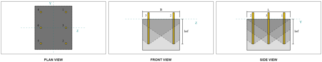
重要的是要注意,施加剪切撬的锚群确定与剪切突破不同. 因此, 仍必须检查设计中的锚点以确定它们是否 行为 有一个 团体 或AS 单锚 反对剪切撬失败. 支持分类为 狭窄的部分 还必须验证,并应遵循与使用相同的条件 张力突破.
从SkyCiv计算, 的 标称拉伸突破强度 锚群是 12.772 ps. 撬动因素 KCP = 2, 设计撬动的容量是:
\( \非V_{cpg} = hy k_{cp} N_{背景} = 0.65 \次 2 \次 12.772 \,\文本{基普} = 16.604 , text{基普} \)
所需的强度是 施加的剪切载荷的结果. 由于所有锚都属于一个组, 将总剪切分配给组.
\( V_{做} = sqrt{(v_y)^ 2 + (v_z)^ 2} = sqrt{(2\,\文本{基普})^ 2 + (2\,\文本{基普})^ 2} = 2.8284 , text{基普} \)
\( V_{做} = 左( \压裂{V_{做}}{N_A} \对) n_{一个,G1} = 左( \压裂{2.8284\,\文本{基普}}{6} \对) \次 6 = 2.8284 , text{基普} \)
由于总剪切负荷小于锚组容量, 2.82 ps < 18.976 ps, 设计撬动的容量是 充足的.
检查一下 #5: 计算锚杆剪切能力
回想一下这个设计示例, 剪切分配给所有锚. 因此,每个锚的总剪切负荷是其Vy负载份额及其eS ess vz负载的结果.
\( v_{做,和} = frac{v_y}{N_A} = frac{2\,\文本{基普}}{6} = 0.33333 , text{基普} \)
\( v_{做,与} = frac{v_z}{N_A} = frac{2\,\文本{基普}}{6} = 0.33333 , text{基普} \)
\( V_{做} = sqrt{(v_{做,和})^ 2 + (v_{做,与})^ 2} \)
\( V_{做} = sqrt{(0.33333\,\文本{基普})^ 2 + (0.33333\,\文本{基普})^ 2} = 0.4714 , text{基普} \)
这给了 锚杆上的剪切应力 作为:
\( f_v = frac{V_{做}}{一个_{杆}} = frac{0.4714\,\文本{基普}}{0.19635\,\文本{在}^ 2} = 2.4008 , text{KSI} \)
因为存在盘洗衣机, 一个 偏心剪切负荷 在锚杆中诱导. 偏心率是从混凝土支撑到板垫圈中心的一半距离的一半, 计算底板的厚度. 参考 AISC 设计指南 1, 3RD版部分 4.3.3.
\( e = 0.5 \剩下( \压裂{t_{PW}}{2} + t_{BP} \对) = 0.5 \时代左( \压裂{0.25\,\文本{在}}{2} + 0.75\,\文本{在} \对) = 0.4375 , text{在} \)
然后将来自偏心剪切的时刻表示为 锚杆中的轴向应力. 使用部分模量, 由于这一刻引起的轴向应力被计算为:
\( z_{杆} = frac{\pi}{32} (D_A)^3 = frac{\pi}{32} \次 (0.5\,\文本{在})^3 = 0.012272 , text{在}^ 3 \)
\( f_t = frac{V_{做} Ë}{z_{杆}} = frac{0.4714\,\文本{基普} \时间0.4375 , text{在}}{0.012272\,\文本{在}^ 3} = 16.806 , text{KSI} \)
ACI锚杆剪切能力:
下列的 ACI 318-19 条款 17.7.1, 然后确定设计强度. 一个 0.8 还原因子 由于存在 灌浆垫. 因此,设计能力是:
\( \非V_{至,这里} = 0.8 \φ 0.6 一个_{我知道,v} F_{乌塔} = 0.8 \次 0.65 \次 0.6 \时间0.1419 文本{在}^2 times 90 文本{KSI} = 3.9845 text{基普} \)
作为备选, 的 SkyCiv底板软件 允许 0.8 简化被禁用, 并在计算中使用实际的灌浆垫厚度. 在这种情况下, 总偏心率包括灌浆垫, 并且剪切和轴向强度是根据AISC规定确定的.
AISC锚杆剪切能力:
第一, 的 标称剪切和拉伸应力 确定针对A325杆.
\( F_{NV} = 0.45 F_{ü,无} = 0.45 \次 120\ \文本{KSI} = 54\ \文本{KSI} \)
\( F_{恩特} = 0.75 F_{ü,无} = 0.75 \次 120\ \文本{KSI} = 90\ \文本{KSI} \)
AISC方法使用 AISC 360-22 情商. J3-3A, 可以表达为包括轴向应力的影响. 这是如下执行的.
\( f’_{NV} = min left( 1.3 F_{NV} – \剩下( \压裂{F_{NV}}{\phi f_{恩特}} \对) f_t,\; F_{NV} \对) \)
\( f’_{NV} = min left( 1.3 \次 54\ \文本{KSI} – \剩下( \压裂{54\ \文本{KSI}}{0.75 \次 90\ \文本{KSI}} \对) \次 16.806\ \文本{KSI},\; 54\ \文本{KSI} \对) = 54\ \文本{KSI} \)
然后将AISC方法的设计剪切能力计算为:
\( \φR_{ñ,\Mathrm{AISC}} = phi f’_{NV} 一个_{杆} = 0.75 \次 54\ \文本{KSI} \次 0.19635\ \文本{在}可以假设为 7.9522\)
确保涵盖这两种方法, 理事能力被视为两者中的较小者, 这是 3.98 基普.
\( \phi v_n = min 左( \非V_{至,这里},\; \φR_{ñ,\Mathrm{AISC}} \对) = min (3.9845\ \文本{基普},\; 7.9522\ \文本{基普}) = 3.9845\ \文本{基普} \)
由于每个锚杆的剪切负载小于剪切锚杆的固定杆的容量, 0.47 基普 < 3.98 基普, 设计锚杆剪切能力是 充足的.
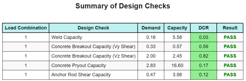
设计概要
的 SkyCiv底板设计软件 可以自动为此设计示例生成逐步计算报告. 它还提供了执行的检查及其结果比率的摘要, 一目了然地使信息易于理解. 以下是示例摘要表, 报告中包括.
SkyCiv样本报告
查看 SkyCiv 底板设计报告的详细程度和清晰度. 该报告包括所有关键的设计检查, 方程式, 并以清晰易读的格式呈现结果. 完全符合设计标准. 单击下面查看使用 SkyCiv 底板计算器生成的示例报告.
购买基板软件
单独购买基本板设计模块的完整版本,而没有任何其他SkyCiv模块. 这为您提供了底板设计的完整结果, 包括详细报告和更多功能.