基本板设计示例使用en 1993-1-8-2005, 在 1993-1-1-2005 和EN 1992-1-1-2004
问题陈述
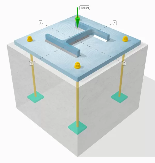
确定设计的列板连接是否足以容纳100 kn压缩负荷.
给定数据
柱:
列部分: 他 200 乙
列区域: 7808 毫米2
列材料: S235
底盘:
基板尺寸: 400 毫米× 400 毫米
基板厚度: 20 毫米
底板材料: S235
灌浆:
灌浆厚度: 20 毫米
具体:
混凝土尺寸: 450 毫米× 450 毫米
混凝土厚度: 380 毫米
混凝土材料: C20/25
焊缝:
仅通过焊缝传输的压缩负荷? 不
SkyCiv 免费工具中的模型
立即使用我们的免费在线工具对上面的底板设计进行建模! 无需注册.
分步计算
检查一下 #1: 计算焊接容量
由于压缩负荷不是单独通过焊接传递的, 需要适当的接触轴承表面以确保负载通过轴承转移. 参考 在 1090-2:2018 条款 6.8 用于接触轴承准备.
另外, 使用最小焊接尺寸 在Eurocode中指定.
检查一下 #2: 计算混凝土轴承能力和基板产量能力
第一步是确定关节的设计抗压强度, 这取决于支撑的几何形状 (木结构) 和加载区域的几何形状 (基板).
我们首先计算α因子, 这说明了集中力在基础内的扩散.
根据 在 1992-1-1:2004, 条款 6.7, α系数是加载面积与最大分布面积的比率, 其形状与加载区域相似.
我们将使用来自 部分 6.1 多层钢结构部分 5 通过 Arcelor Mittal, Peiner载体, 和 Corus 计算α因子.
\(
\alpha = min 左(
1 + \压裂{t_{\文本{浓}}}{\最高(L_{\文本{BP}}, b_{\文本{BP}})},
1 + 2 \剩下( \压裂{E_H}{L_{\文本{BP}}} \对),
1 + 2 \剩下( \压裂{E_B}{b_{\文本{BP}}} \对),
3
\对)
\)
\(
\alpha = min 左(
1 + \压裂{380 \, \文本{毫米}}{\最高(400 \, \文本{毫米}, 400 \, \文本{毫米})},
1 + 2 \剩下( \压裂{25 \, \文本{毫米}}{400 \, \文本{毫米}} \对),
1 + 2 \剩下( \压裂{25 \, \文本{毫米}}{400 \, \文本{毫米}} \对),
3
\对)
\)
\(
\alpha = 1.125
\)
哪里,
\(
e_h = frac{L_{\文本{浓}} – L_{\文本{BP}}}{2} = frac{450 \, \文本{毫米} – 400 \, \文本{毫米}}{2} = 25 \, \文本{毫米}
\)
\(
e_b = frac{b_{\文本{浓}} – b_{\文本{BP}}}{2} = frac{450 \, \文本{毫米} – 400 \, \文本{毫米}}{2} = 25 \, \文本{毫米}
\)
一旦定义了几何形状, 然后,我们将使用混凝土的抗压强度 在 1992-1-1:2004, 情商. 3.15.
\(
F_{光盘} = frac{\α_{抄送} F_{钢底板设计欧洲规范}}{\gamma_c} = frac{1 \次 20 \, \文本{兆帕}}{1.5} = 13.333 \, \文本{兆帕}
\)
下一个, 我们假设Beta系数的值. 由于灌浆存在, beta值可以是 2/3. 我们将使用来自 在 1993-1-8:2005 情商. 6.6, 和 在 1992-1-1:2004 情商. 6.63.
\(
F_{钢底板设计欧洲规范} = beta alpha f_{光盘} = 0.66667 \次 1.125 \次 13.333 \, \文本{兆帕} = 10 \, \文本{兆帕}
\)
第二部分涉及计算基板的产量能力.
由于我们已经具有连接的设计强度, 我们将使用它来确定底板的最小悬臂距离,该底板经历了完整的轴承负荷. 我们将参考 科幻P358 页面上的示例 243 和 在 1993-1-1:2005 条款 6.2.5.
\(
C = T_{\文本{BP}} \sqrt{\压裂{F_{y_{\文本{BP}}}}{3 F_{钢底板设计欧洲规范} \伽玛_{莫0}}} = 20 \, \文本{毫米} \次 sqrt{\压裂{225 \, \文本{兆帕}}{3 \次 10 \, \文本{兆帕} \次 1}} = 54.772 \, \文本{毫米}
\)
我们将使用此维度来计算基板的有效面积. 'c’ 我们计算的维度可能重叠或不重叠在法兰附近. 如果重叠, 我们将假设该部分是矩形部分. 如果不重叠, 我们将采用列的形状.
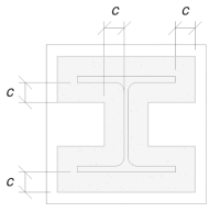
没有重叠
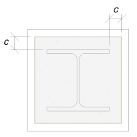
与重叠
我们确定‘c’ 维度不会重叠. 因此, 使用 科幻P358 pg. 243, 有效区域是:
\(
a_e = 4c^2 + P_{\文本{上校}}C + 一个_{\文本{上校}} = 4 \时间54.772^2 \, \文本{毫米}^ 2 + 1182 \, \文本{毫米} \次 54.772 \, \文本{毫米} + 7808 \, \文本{毫米}可以假设为 84549 \, \文本{毫米}^ 2
\)
重要的是要注意,有效区域不应小于基板区域.
最后, 我们将使用 在 1993-1-8:2005 情商. 6.6, 和EN 1992-1-1:2004, 情商. 6.63 计算基板连接的设计轴承电阻.
\(
N_{路} = 左( \分(A_e, A_0) \对) F_{钢底板设计欧洲规范} = 左( \分(84549 \, \文本{毫米}^ 2, 160000 \, \文本{毫米}^ 2) \对) \次 10 \, \文本{兆帕} = 845.49 \, \文本{千牛}
\)
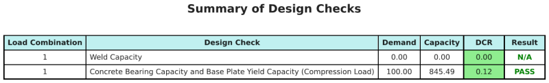
以来 845.49 千牛 > 100 千牛, 设计是 充足的!
设计概要
SkyCiv基板设计软件可以自动生成此设计示例的分步计算报告. 它还提供了执行的检查及其结果比率的摘要, 一目了然地使信息易于理解. 以下是示例摘要表, 报告中包括.
SkyCiv样本报告
查看 SkyCiv 底板设计报告的详细程度和清晰度. 该报告包括所有关键的设计检查, 方程式, 并以清晰易读的格式呈现结果. 完全符合设计标准. 单击下面查看使用 SkyCiv 底板计算器生成的示例报告.
购买基板软件
单独购买基本板设计模块的完整版本,而没有任何其他SkyCiv模块. 这为您提供了底板设计的完整结果, 包括详细报告和更多功能.