您来到这里可能是因为您使用工程软件设计了锚地, 一项或多项检查失败, 并且你不确定接下来要改变什么.
本教程是为想要了解的新工程师和工程专业的学生编写的 ACI 下的锚杆失效模式 318-19 以及如何逻辑地调整设计. 这不是代码的替代品. 完整的规定和要求, 总是参考 ACI 318-19 章节 17.
这里的目标是帮助您认识到 什么是失败的, 为什么它失败了, 和 哪些设计参数实际上增加了容量, 而不是随机改变输入.
如果您想了解如何在设计工作流程中逐步应用这些检查, 您还可以参考 SkyCiv 底板设计软件, 它报告所有 ACI 锚点检查以及完整的计算.
什么是锚?
锚通常是嵌入混凝土中的钢棒,用于连接另一个结构元件, 最常见的是钢基板. 锚传递张力, 剪力, 或从钢材到混凝土支撑的合力.
锚栓常见按安装方式分类.
预埋锚栓
预埋锚栓在浇注混凝土之前放置,并随着混凝土硬化而嵌入.
后安装锚栓
通过钻孔并将后装锚栓安装到硬化混凝土中,并使用:
- 机械膨胀
- 粘合剂或化学粘合
哪一个更好?
这两种锚类型本质上都不是更好. 选择取决于可施工性, 项目限制, 和可用性. 例如, 如果将钢柱添加到现有板或基础上, 预埋锚不再是一种选择, 通常使用后安装锚.
可用性也很重要, 作为锚点类型, 尺寸, 和安装限制取决于制造商的供应. 常见的锚栓厂家有 喜利得, 德瓦尔特, 和 费舍尔, 每个都提供不同的机械和粘合剂锚固系统以及产品特定的设计数据和安装要求.
单个锚点与锚点组
当锚点检查失败时, 故障并不总是只发生在一个锚点上. 取决于布局, 失效可能发生在单个锚点或一组共同作用的锚点上. ACI 318 做出这种区分是因为控制故障模式和容量可能有很大不同.
失败是否被评估为 单锚失效 或一个 锚定组失效 主要取决于 投影破坏面的重叠. 这种重叠通常由锚点间距控制, 埋置深度, 和边距.
在设计过程中可视化此行为, 工具,例如 SkyCiv 底板设计软件 显示预计失效区域并自动确定锚点是单独评估还是根据几何形状作为一组进行评估.
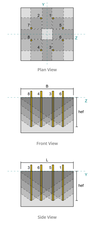
单锚
如果锚栓间距较宽或埋置深度较浅, 他们的预计失效区域不重叠. 在这种情况下, 在单个锚点级别评估失效. 一个锚点可能会在相邻锚点没有显着贡献的情况下达到其极限.
锚群
当锚栓放置得更近且嵌入深度足够时, 它们的预计破坏面重叠. 在这种情况下, 具体限制了整个团体的能力, 当组合预计失效面积达到其极限时,就会发生失效. 群体容量不等于单个锚点容量之和.
这种区别至关重要,因为一些 ACI 张力和剪切检查会根据失效是由单个锚固件还是由锚固件组控制而明显变化. 错误地识别控制故障类型可能会导致不保守或过于保守的设计.
设计示例
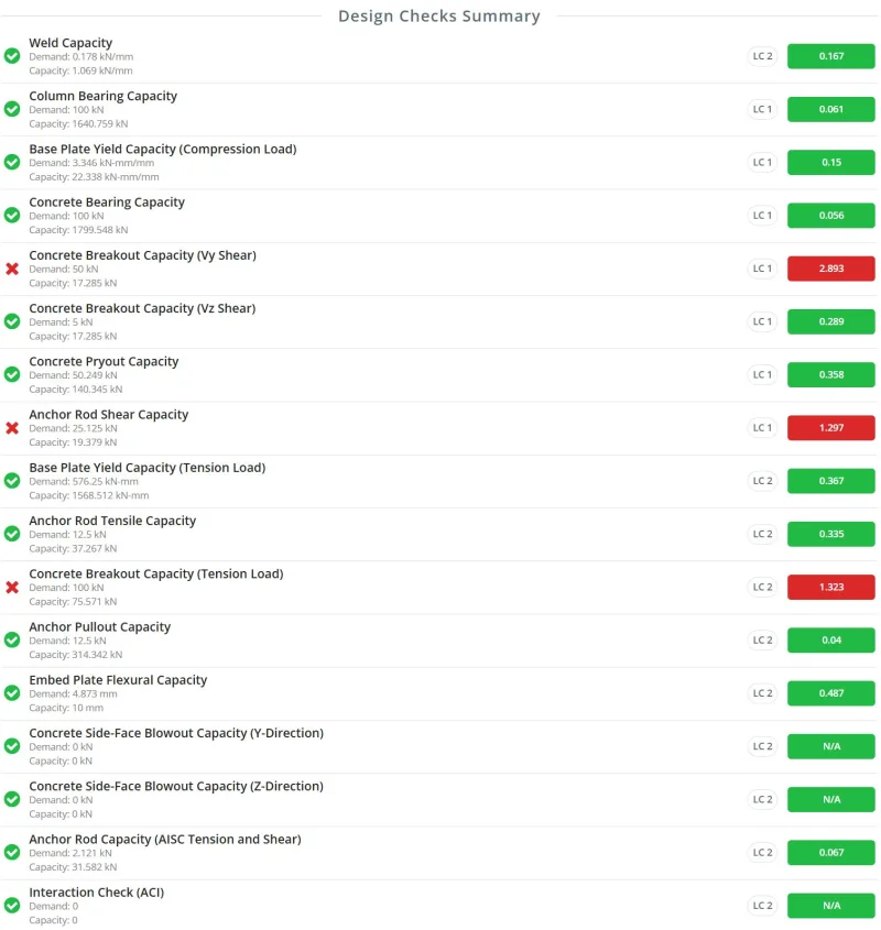
设计实例说明 单锚点和锚点组失败 可以在 SkyCiv 底板设计资源中找到. 这是由以下人员执行的一组设计检查示例: SkyCiv 底板设计软件.
根据 ACI 进行锚固张力检查 318-19
当锚受到拉力时, ACI 318-19 需要多次检查. 每个检查对应不同的物理故障机制. 一旦你了解了这个机制, 调整设计变得更加容易.
钢的拉伸强度
锚杆钢校核考虑锚杆钢的屈服和断裂.
如何提高钢材的拉伸能力
选择较大的锚栓直径
更大的直径提供更大的拉伸面积. 用于直径选择, 许多工程师从以下范围开始 1/2 英寸至 3/4 英寸. 如果需求高于预期, 增加直径. 这种判断力会随着经验的积累而提高.
增加锚固材料强度
较高的材料等级会增加容量,但也会增加成本。常见的锚固材料包括 ASTM F1554. 实用的设计方法是从较低的等级开始,例如 Grade 36, 然后增加到等级 55 或等级 105 仅当需求需要时.
提供更多锚点
如果锚栓直径和材料等级已经最大化并且钢张力检查仍然起作用, 在同一行中添加更多锚点可能是一种选择. 这通常需要调整间距, 边缘距离, 或底板尺寸. 允许添加额外的行, 但它改变了负载分布并且应该是 仔细评估.
容量方程:
\( N_{至} = A_{我知道,ñ} F_{乌塔} \)
混凝土拉伸断裂强度
当混凝土的锥形部分与支撑分离时,就会发生混凝土破裂. 在这种情况下, 锚钢完好无损, 但周围的混凝土失效了.
这种失效模式适用于带头锚, 膨胀锚栓, 螺旋锚栓, 和底切锚栓.
如何提高混凝土破碎能力
增加嵌入深度
理想的破碎锥体是从锚栓的嵌入端延伸到混凝土表面. 增加嵌入深度可扩大锥体并显着提高容量. 嵌入深度还直接增加了 ACI 定义的基本突破强度.
增加锚杆间距
紧密间隔的锚限制了预计失效区域的宽度. 增加间距可实现更大的有效突破区域, 特别是对于锚定团体.
增加边缘距离
放置在边缘附近的锚无法形成完整的突破锥体. 增加边缘距离通常会导致容量显着增加.
使用更高强度的混凝土
从较低等级混凝土升级到较高等级混凝土可提高基本突破强度,并且在几何形状受到限制时通常很有效.
适当时假设混凝土不开裂
未开裂的混凝土提供略高的容量. 只有在合理的情况下才应使用该假设, 因为它改变了设计假设.
提供旨在承受张力的加固
当钢筋经过明确设计和详细设计以承受锚固拉力时, 混凝土突破检查可能会被免除. 这一定是一个有意的设计决定, 不是一个假设.
单锚的容量方程:
\( N_{CB} = frac{一个_{数控}}{一个_{记住}} \psi_{编辑,ñ} \psi_{C,ñ} \psi_{cp,ñ} N_b \)
锚定组的容量方程:
\( N_{背景} = frac{一个_{数控}}{一个_{记住}} \psi_{欧共体,ñ} \psi_{编辑,ñ} \psi_{C,ñ} \psi_{cp,ñ} N_b \)
锚杆抗拉强度
当锚杆从混凝土中拉出但未形成完整的脱离锥体时,就会发生拉拔失效. 该检查适用于预埋锚栓和某些后装机械锚栓,并进行评估 仅单个锚点.
对于后安装锚栓, 容量通过实验测试确定. 用于预埋锚栓, 容量通常基于锚尺寸.
在铸入式带头螺柱中, 容量由嵌入端的轴承控制, 当处于钩状锚中时, 由有效钩长控制.
如何修复拔出故障
使用更宽或更厚的嵌入板或更大的螺栓头 (有头锚)
对于带有嵌入式端部的锚栓, 增加承载面积提高承载能力. 使用嵌入式板时, 增加板材尺寸或厚度. 适用于带有嵌入式头部或螺母的锚栓, 在嵌入端选择较大的头部或螺母会增加轴承面积.
延长锚钩或增加杆直径 (钩状锚)
短钩或小锚杆可能导致拉出, 即使混凝土锥体没有失效. 更长的钩子或更大的杆可增加容量并降低拉出的风险.
使用更高强度的混凝土
从较低等级混凝土升级到较高等级混凝土可提高抗拉强度,并且在几何形状受到限制时通常很有效.
适当时使用不开裂混凝土
未开裂的混凝土提供更好的抗拔性. 仅当设计条件证明合理时才应假设这一点.
拉出故障通常通过改善轴承条件而不是改变间距或边缘距离来解决.
头部容量方程:
\( N_{pn} = psi_{C,p} N_p \)
哪里,
\( N_p = 8A_{brg}f_c’ \)
Hooked 的容量方程:
\( N_{pn} = psi_{C,p} N_p \)
哪里,
\( N_p = 0.9f_c’e_h d_a \)
混凝土侧面爆破强度
当嵌入相对较深的锚栓放置得太靠近自由边缘时,会发生侧面爆裂. 而不是向上形成突破锥体, 圆锥体向侧面延伸, 导致混凝土侧面断裂、爆裂.
这种失效模式由嵌入深度和边缘距离之间的关系决定. 当这些参数以某种方式调整大小时, 此故障机制可能不适用.
由于混凝土锥体可能重叠, 必须检查单个锚点和锚点组.
如何修复侧面爆裂
增加边缘距离
增加边缘距离可提高标称强度. 也, a much larger edge distance i.e.\( ca_1 > \压裂{H_{ef}}{2.5 }\) 使得此故障不适用.
调整锚点组的锚点间距
在锚定组中, 多个锚杆可能导致侧面同时爆裂. 将锚点间隔得更远, 同时仍然允许一些锥体重叠, 增加有效混凝土锥体尺寸和容量.
减少锚杆埋置深度
靠近边缘的锚杆太长会增加井喷的可能性. 使用相对于边缘距离较短的杆可能会使此检查不适用.
使用更高强度的混凝土
从较低等级混凝土升级到较高等级混凝土可提高侧面爆裂强度,并且在几何形状受到限制时通常很有效.
单锚的容量方程:
\( N_{某人} = 160c_{a1}\sqrt{一个_{brg}}\lambda_a\sqrt{f'_c} \)
锚定组的容量方程:
\( N_{作为} = 左(1 + \压裂{s}{6C_{a1}}\对) N_{某人} \)
胶粘剂的粘结强度
用于后安装粘性锚栓, 在拉力下检查粘合强度. 根据粘结锚杆的影响面积和特征粘结应力计算承载力. 特征粘合应力值来自实验测试, 如果测试数据不可用, ACI 的保守值 318-19 桌子 17.6.2.5 可以使用.
由于影响区域可能重叠, 必须评估单个锚点和锚点组.
债券容量已占:
-
锚栓和粘合剂之间的粘合
-
粘合剂与混凝土之间的粘结
如何提高债券能力
增加锚栓直径
较大的锚栓直径增加了基本粘合强度的能力, 以及影响范围. 影响区域的几何形状受直径影响很大.
增加嵌入深度
更深的嵌入增加了粘性锚栓的基本粘合强度.
增加间距和边缘距离
对于靠近边缘的锚点组或单个锚点, 调整间距和边缘距离消除了对总影响区域的限制.
使用具有更高特性粘合应力的粘合剂
选择具有较高粘合强度的粘合剂可提高容量. 特征结合应力越大,影响范围越大, 从而增加容量.
单锚的容量方程:
\( N_a = frac{一个_{已经}}{一个_{奈绪}} \psi_{编辑,已经} \psi_{cp,已经} N_{BA} \)
锚定组的容量方程:
\( N_{股份公司} = frac{一个_{已经}}{一个_{奈绪}} \psi_{欧共体,已经} \psi_{编辑,已经} \psi_{cp,已经} N_{BA} \)
根据 ACI 进行锚剪剪力检查 318-19
锚杆抗剪能力
与锚杆的抗拉能力类似, 锚钢校核考虑了锚钢由于施加的剪切载荷而产生的屈服和断裂. 当周围混凝土失效之前锚杆的钢材强度已达到时,就会发生这种失效模式.
锚杆的抗剪能力主要取决于锚杆直径, 钢材的材料强度, 以及抵抗所施加载荷的锚的数量.
如何提高钢材剪切能力
选择较大的锚栓直径
与锚杆抗拉强度相似, 锚栓的抗剪强度取决于其物理尺寸. 增加锚栓直径会增加钢材的横截面积, 这导致更高的剪切能力.
增加锚固材料强度
如果由于几何限制而无法增加直径, 可以考虑选择更强的锚固材料. 常见的锚杆牌号包括 36, 年级 55, 和等级 105. 强度等级越高,对剪切力的抵抗力就越大.
添加更多锚点
另一种方法是增加抵抗载荷的锚的数量. 添加更多锚固件可将施加的力分布到其他元件上,并减少每个锚固件的剪切需求.
埋入式螺柱锚的承载力方程:
\( V_{至} = A_{我知道,V} F_{乌塔} \)
预埋带头螺栓和钩形螺栓锚的承载力方程:
\( V_{至} = 0.6A_{我知道,V} F_{乌塔} \)
如果存在组合灌浆垫, 锚杆的抗剪强度降低为 80 根据 ACI 规定的百分比.
混凝土因剪切而破裂
当混凝土的锥形部分由于施加的剪切力而与支撑分离时,就会出现混凝土的剪切破坏强度. 当剪切平行于混凝土边缘或垂直于边缘作用时,可能会发生这种故障.
ACI 规定表明,平行于边缘的剪切能力通常大于垂直于边缘的剪切能力. 然而, 仍然建议检查两个方向,如实施 SkyCiv 底板设计软件.
如何提高混凝土破碎能力
增加边缘距离
增加锚杆与混凝土边缘的边缘距离可以形成更大的破碎锥. 锚点距离边缘越远, 预计破坏面越大. 混凝土的基本剪切断裂强度也与边缘距离直接相关.
增加锚点间距
增加锚固件之间的间距可以扩大锚固件组的投影突破区域. 紧密间隔的锚限制了破碎锥的发展, 而较大的间距允许形成更大的破坏面.
增加厚度
破碎锥可能受到混凝土支撑厚度的限制. 如果锚端距离支撑底部太近, 破碎锥无法完全发育. 增加混凝土支撑的厚度可以实现更完整的突破投影.
增加锚长度
混凝土的基本剪切断裂强度部分取决于锚杆的承载长度. 对于具有恒定刚度的锚, 该长度一般等于锚杆埋置深度. 用于扭矩控制膨胀锚栓, 承载长度通常取锚栓直径的两倍. 在所有情况下, 该长度不应超过锚直径的八倍.
增加锚栓直径
增加锚栓直径也会增加混凝土的基本破坏强度.
使用更高强度的混凝土
使用更高强度的混凝土可提高基本突破强度. 当间距或边缘距离等几何参数无法轻易增加时,这种方法通常很有效.
适当时假设混凝土不开裂
当假定混凝土不开裂时,混凝土的破裂能力稍高. 仅当设计条件证明合理时才应使用此假设.
提供旨在承受张力的加固
如果有意设计和详细说明加固以承载锚固力, 混凝土突破可能会被阻止. 当提供正确设计的加固时, ACI 允许免除突破检查.
单锚的承载能力方程:
\( V_{CB} = frac{一个_{VC}}{一个_{压控振荡器}} \psi_{编辑,V} \psi_{C,V} \psi_{H,V} v_b \)
锚定组的容量方程:
\( V_{背景} = frac{一个_{VC}}{一个_{压控振荡器}} \psi_{欧共体,V} \psi_{编辑,V} \psi_{C,V} \psi_{H,V} v_b \)
混凝土因剪切而撬出
混凝土撬出是与受剪力作用的锚相关的另一种失效模式. 当锚由于施加的剪切力而向上拉动混凝土的楔形部分时,就会发生这种故障.
根据ACI规定, 混凝土撬出强度与混凝土拉伸断裂强度有关. 这种失效模式适用于多种锚栓类型,包括带头锚栓, 膨胀锚栓, 螺旋锚栓, 和底切锚栓.
如何提高混凝土撬出能力
增加嵌入深度
理想的破碎锥体是从锚栓的嵌入端延伸到混凝土表面. 增加嵌入深度会扩大该锥体并显着增加撬出能力. 嵌入深度还增加了 ACI 定义的基本突破强度. 此外, 更大的嵌入深度会导致更大的 克CP 撬出强度计算中使用的系数, 这进一步增加了撬出能力.
增加锚点间距
紧密间隔的锚限制了预计的突破区域. 增加锚之间的间距可以形成更大的有效突破区域, 特别是对于锚定团体.
增加边缘距离
位于边缘附近的锚无法形成完整的突破锥体. 增加边缘距离可以扩大突破表面并提高撬出能力.
使用更高强度的混凝土
使用更高强度的混凝土可提高基本破裂强度,并且在无法修改几何参数时可以提高撬出能力.
适当时假设混凝土不开裂
非开裂混凝土的承载能力略高. 仅当设计条件证明合理时才应使用此假设.
单锚的承载能力方程:
\( V_{cp} 检查锚容量{cp} N_{cp} \)
锚定组的容量方程:
\( V_{cpg} 检查锚容量{cp} N_{cpg} \)
根据 ACI 进行锚固张力和剪切相互作用检查 318-19
本节即将发布.