基本板设计示例使用AISC 360-22 和ACI 318-19
问题陈述
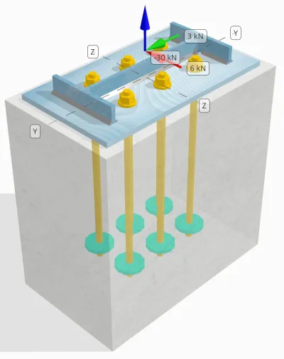
确定设计的柱与底板连接是否足以满足 30 kN 拉力载荷, 3 kN Vy 剪切载荷, 和 6 kN Vz 剪切载荷.
给定数据
柱:
列部分: 宽14x30
列区域: 5709.7 毫米2
列材料: A992
底盘:
基板尺寸: 250 毫米× 250 毫米
基板厚度: 12 毫米
底板材料: A992
灌浆:
灌浆厚度: 0 毫米
具体:
混凝土尺寸: 300 毫米× 500 毫米
混凝土厚度: 500 毫米
混凝土材料: 20.7 兆帕
破裂或无裂缝: 破裂
锚:
锚直径: 16 毫米
有效嵌入长度: 400 毫米
锚定结局: 圆板
嵌入式板直径: 70 毫米
嵌入式板厚度: 10 毫米
钢材: F1554 Gr.55
剪切平面中的螺纹: 包括
焊缝:
焊缝尺寸: 7 毫米
填充金属分类: E70XX
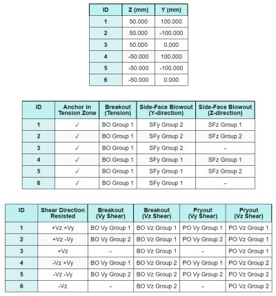
锚数据 (从 SkyCiv计算器):
SkyCiv 免费工具中的模型
立即使用我们的免费在线工具对上面的底板设计进行建模! 无需注册.
注意
此设计示例的目的是演示涉及并发剪切和轴向载荷的容量检查的分步计算. 一些必需的检查已经在前面的设计示例中讨论过. 请参阅每个部分提供的链接.
分步计算
检查一下 #1: 计算焊接容量
确定同时加载下的焊接能力, 我们首先需要计算焊接需求,因为 剪切载荷 以及由于的焊接需求 拉力负荷. 你可以参考这个 链接 获得焊缝剪切要求的程序, 还有这个 链接 满足张力焊接要求.
对于这个设计, 的 网络焊接需求 发现由于拉力载荷如下, 其中应力表示为 单位长度力.
\(r_{ü,\文本{普拉特桁架和普拉特桁架设计的技术研究}} = frac{T_{ü,\文本{锚}}}{由使用公式计算的最小值控制{\文本{效果}}} = frac{5\ \文本{千牛}}{93.142\ \文本{毫米}} = 0.053681\ \文本{千牛/毫米}\)
此外, 的 柱截面任意部位的焊接应力 由于剪切载荷确定为:
\(v_{你} = frac{v_y}{L_{\文本{焊接}}} = frac{3\ \文本{千牛}}{1250.7\ \文本{毫米}} = 0.0023987\ \文本{千牛/毫米}\)
\(v_{到} = frac{v_z}{L_{\文本{焊接}}} = frac{6\ \文本{千牛}}{1250.7\ \文本{毫米}} = 0.0047973\ \文本{千牛/毫米}\)
由于在拉力和剪切载荷的组合 普拉特桁架和普拉特桁架设计的技术研究, 我们需要得到结果. 将其表示为每单位长度的力, 我们有:
\(r_u = sqrt{(r_{ü,\文本{普拉特桁架和普拉特桁架设计的技术研究}})^ 2 + (v_{你})^ 2 + (v_{到})^ 2}\)
\(r_u = sqrt{(0.053681\ \文本{千牛/毫米})^ 2 + (0.0023987\ \文本{千牛/毫米})^ 2 + (0.0047973\ \文本{千牛/毫米})^ 2}\)
\(r_u = 0.053949\ \文本{千牛/毫米}\)
为了 法兰, 仅存在剪应力. 从而, 结果是:
\(r_u = sqrt{(v_{你})^ 2 + (v_{到})^ 2}\)
\(r_u = sqrt{(0.0023987\ \文本{千牛/毫米})^ 2 + (0.0047973\ \文本{千牛/毫米})^ 2} = 0.0053636\ \文本{千牛/毫米}\)
下一个, 我们计算 焊接能力. 法兰用, 我们确定角度 θ 使用 电压 和 你 负载.
\( \θ = tan^{-1}\!\剩下(\压裂{v_{你}}{v_{到}}\对) = tan^{-1}\!\剩下(\压裂{0.0023987\ \文本{千牛/毫米}}{0.0047973\ \文本{千牛/毫米}}\对) = 0.46365\ \文本{工作} \)
所以, 的 克德斯 系数和焊接能力的计算公式为 AISC 360-22 情商. J2-5 和 情商. J2-4.
\(钢底板设计欧洲规范{DS} = 1.0 + 0.5(\没有(\θ))^{1.5} = 1 + 0.5 \次 (\没有(0.46365\ \文本{工作}))^{1.5} = 1.1495\)
\(\phi r_{ñ,FLG} = phi,0.6,F_{EXX}\,E_w,k_{DS} = 0.75 \次 0.6 \次 480\ \文本{兆帕} \次 4.95\ \文本{毫米} \次 1.1495 = 1.2291\ \文本{千牛/毫米}\)
对于网络, 我们计算角度 θ 使用不同的公式. 注意 哇 公式中使用它是因为它表示平行于焊接轴的载荷.
\( \θ = cos^{-1}\!\剩下(\压裂{v_{你}}{r_u}\对) = cos^{-1}\!\剩下(\压裂{0.0023987\ \文本{千牛/毫米}}{0.053949\ \文本{千牛/毫米}}\对) = 1.5263\ \文本{工作} \)
使用 AISC 360-22 情商. J2-5 和 情商. J2-4, 的 克德斯 系数和由此产生的焊接能力以相同的方式确定.
\(钢底板设计欧洲规范{DS} = 1.0 + 0.5(\没有(\θ))^{1.5} = 1 + 0.5 \次 (\没有(1.5263\ \文本{工作}))^{1.5} = 1.4993\)
\(\phi r_{ñ,普拉特桁架和普拉特桁架设计的技术研究} = phi,0.6,F_{EXX}\,E_w,k_{DS} = 0.75 \次 0.6 \次 480\ \文本{兆帕} \次 4.95\ \文本{毫米} \次 1.4993 = 1.603\ \文本{千牛/毫米}\)
最后, 我们表演 贱金属检查 对于立柱和底板, 然后获得控制贱金属容量.
\( \phi r_{NBM,上校} = phi,0.6,F_{ü,上校}\,t_{上校,一半} = 0.75 \次 0.6 \次 448.2\ \文本{兆帕} \次 3.429\ \文本{毫米} = 0.6916\ \文本{千牛/毫米} \)
\( \phi r_{NBM,BP} = phi,0.6,F_{ü,BP}\,t_{BP} = 0.75 \次 0.6 \次 400\ \文本{兆帕} \次 12\ \文本{毫米} = 2.1595\ \文本{千牛/毫米} \)
\( \phi r_{NBM} = 最小大(\phi r_{NBM,BP},\ \phi r_{NBM,上校}\大的) = min(2.1595\ \文本{千牛/毫米},\ 0.6916\ \文本{千牛/毫米}) = 0.6916\ \文本{千牛/毫米} \)
然后我们比较 角焊缝能力 和 贱金属产能 对于焊接要求 法兰和腹板分开.
以来 0.053949 千牛/毫米 < 0.6916 千牛/毫米, 焊接容量是 充足的.
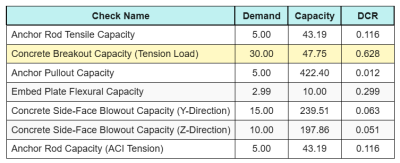
检查一下 #2: 计算由于张力负载而导致的基本板弯曲屈服能力
底板弯曲屈服能力的设计示例已在底板拉伸设计示例中讨论过. 请参阅此链接以了解分步计算.
检查一下 #3: 计算锚杆拉伸能力
锚杆拉伸能力的设计示例已在张力底板设计示例中讨论过. 请参阅此链接以了解分步计算. 请参阅此链接以了解分步计算.
检查一下 #4: 计算张力的混凝土突破能力
混凝土抗拉破坏能力的设计实例已在抗拉底板设计实例中讨论过. 请参阅此链接以了解分步计算. 请参阅此链接以了解分步计算.
检查一下 #5: 计算锚推拉力
锚杆拉出能力的设计示例已在张力底板设计示例中讨论过. 请参阅此链接以了解分步计算. 请参阅此链接以了解分步计算.
检查一下 #6: 计算嵌入板弯曲能力
预埋板弯曲屈服能力补充校核的设计实例已在张力底板设计实例中讨论过. 请参阅此链接以了解分步计算.
检查一下 #7: 计算Y方向的侧面井喷容量
计算 侧面爆裂 (SFBO) 容量, 我们首先确定总数 张力 在最靠近边缘的锚点上. 对于这次检查, 我们将评估沿 Y方向.
由于 SFBO 的失效锥体投影沿 Y 方向重叠, 锚点被视为 锚群.
锚杆组的总拉力需求计算为:
\(N_{做} = 左(\压裂{n_x}{n_{一个,Ť}}\对) n_{和,G1} = 左(\压裂{30\ \文本{千牛}}{6}\对) \次 3 = 15\ \文本{千牛}\)
下一个, 我们确定 边缘距离:
\(C_{与,\分} = min(C_{\文本{剩下},G1},\ C_{\文本{对},G1}) = min(100\ \文本{毫米},\ 200\ \文本{毫米}) = 100\ \文本{毫米}\)
\(C_{和,\分} = min(C_{\文本{最佳},G1},\ C_{\文本{底部},G1}) = min(150\ \文本{毫米},\ 150\ \文本{毫米}) = 150\ \文本{毫米}\)
使用这些边缘距离, 我们计算 锚定组容量 依据 ACI 318-19 情商. (17.6.4.1).
\(N_{作为} = 左(\压裂{1 + \dfrac{C_{和,\分}}{C_{与,\分}}}{4} + \压裂{s_{和,和,G1}}{6\,C_{与,\分}}\对)\次 13 \时代左(\压裂{C_{与,\分}}{1\ \文本{毫米}}\对)\次 sqrt{\压裂{一个_{brg}}{\文本{毫米}^ 2}}\ \lambda_a sqrt{\压裂{f_c}{\文本{兆帕}}}\次 0.001\ \文本{千牛}\)
\(N_{作为} = 左(\压裂{1 + \dfrac{150\ \文本{毫米}}{100\ \文本{毫米}}}{4} + \压裂{200\ \文本{毫米}}{6\次 100\ \文本{毫米}}\对)\次 13 \时代左(\压裂{100\ \文本{毫米}}{1\ \文本{毫米}}\对)\次 sqrt{\压裂{3647.4\ \文本{毫米}^ 2}{1\ \文本{毫米}^ 2}}\次 1 \次 sqrt{\压裂{20.68\ \文本{兆帕}}{1\ \文本{兆帕}}}\次 0.001\ \文本{千牛}\)
\(N_{作为} = 342.16\ \文本{千牛}\)
在原方程中, 当锚间距小于时应用折减系数 6钙₁, 假设有头锚有足够的边缘距离. 然而, 在这个设计实例中, 以来 钙 < 3钙₁, SkyCiv 计算器应用额外的缩减因子来考虑减少的边缘容量.
最后, 的 SFBO 设计容量 是:
\(\φN_{作为} = phi,N_{作为} = 0.7 \次 342.16\ \文本{千牛} = 239.51\ \文本{千牛}\)
以来 15 千牛 < 239.51 千牛, 沿 Y 方向的 SFBO 容量为 充足的.
检查一下 #8: 计算Z方向的侧面井喷容量
采用与中相同的方法 检查一下 #7, 距离最近的锚的锚组的总拉力需求 Z方向 边缘是:
\(N_{做} = 左(\压裂{n_x}{n_{一个,Ť}}\对)n_{与,G1} = 左(\压裂{30\ \文本{千牛}}{6}\对)\次 2 = 10\ \文本{千牛}\)
的 边缘距离 计算为:
\(C_{和,\分} = min(C_{\文本{最佳},G1},\ C_{\文本{底部},G1}) = min(150\ \文本{毫米},\ 350\ \文本{毫米}) = 150\ \文本{毫米}\)
\(C_{与,\分} = min(C_{\文本{剩下},G1},\ C_{\文本{对},G1}) = min(100\ \文本{毫米},\ 100\ \文本{毫米}) = 100\ \文本{毫米}\)
的 SFBO 标称容量 然后确定为:
\(N_{作为} = 左(\压裂{1 + \dfrac{C_{与,\分}}{C_{和,\分}}}{4} + \压裂{s_{和,与,G1}}{6\,C_{和,\分}}\对)\次 13 \时代左(\压裂{C_{和,\分}}{1\ \文本{毫米}}\对)\次 sqrt{\压裂{一个_{brg}}{\文本{毫米}^ 2}}\ \lambda_a sqrt{\压裂{f_c}{\文本{兆帕}}}\次 0.001\ \文本{千牛}\)
\(N_{作为} = 左(\压裂{1 + \dfrac{100\ \文本{毫米}}{150\ \文本{毫米}}}{4} + \压裂{100\ \文本{毫米}}{6\次 150\ \文本{毫米}}\对)\次 13 \时代左(\压裂{150\ \文本{毫米}}{1\ \文本{毫米}}\对)\次 sqrt{\压裂{3647.4\ \文本{毫米}^ 2}{1\ \文本{毫米}^ 2}}\次 1 \次 sqrt{\压裂{20.68\ \文本{兆帕}}{1\ \文本{兆帕}}}\次 0.001\ \文本{千牛}\)
\(N_{作为} = 282.65\ \文本{千牛}\)
由于边距 钙 仍小于 3钙₁, 应用相同的修改后的折减系数.
最后, 的 SFBO 设计容量 是:
\(\φN_{作为} = phi,N_{作为} = 0.7 \次 282.65\ \文本{千牛} = 197.86\ \文本{千牛}\)
以来 10 千牛 < 197.86 千牛, 沿线的 SFBO 容量 Z方向 是 充足的.
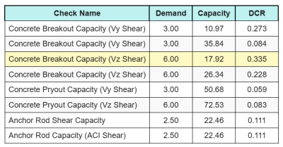
检查一下 #9: 计算突破能力 (vy剪)
Vy 剪切下混凝土突破能力的设计示例已在剪切底板设计示例中讨论. 请参阅此链接以了解分步计算.
检查一下 #10: 计算突破能力 (VZ剪)
Vy 剪切下混凝土突破能力的设计示例已在剪切底板设计示例中讨论. 请参阅此链接以了解分步计算.
检查一下 #11: 计算撬出容量 (vy剪)
抗剪底板设计实例中已经讨论了混凝土抵抗 Vy 剪力引起的撬出破坏能力的设计实例. 请参阅此链接以了解分步计算.
检查一下 #12: 计算撬出容量 (VZ剪)
抗剪底板设计实例中已经讨论了混凝土抵抗 Vy 剪力引起的撬出破坏能力的设计实例. 请参阅此链接以了解分步计算.
检查一下 #13: 计算锚杆剪切能力
锚杆抗剪能力的设计示例已在抗剪底板设计示例中讨论. 请参阅此链接以了解分步计算.
检查一下 #14: 计算锚杆剪力和轴向承载力 (AISC)
确定锚杆在剪切和轴向联合载荷作用下的承载能力, 我们用 AISC 360-22 情商. J3-3A. 在这个计算器中, 重新排列方程,将结果表示为修改后的剪切强度.
的 剪切需求 被定义为 每个锚的剪切载荷.
\(V_{做} = V_{做} = 2.5\ \文本{千牛}\)
的 需求紧张 表示为 拉应力 在锚杆中.
\(F_{乌特} = frac{N_{做}}{一个_{杆}} = frac{5\ \文本{千牛}}{201.06\ \文本{毫米}^ 2} = 24.868\ \文本{兆帕}\)
的 修正剪切力 然后计算锚杆的:
\(f’_{NV} = 分钟!\剩下(1.3\,F_{NV} – \剩下(\压裂{F_{NV}}{\phi f_{恩特}}\对) F_{乌特},\; F_{NV}\对)\)
\(f’_{NV} = 分钟!\剩下(1.3\次 232.69\ \文本{兆帕} – \剩下(\压裂{232.69\ \文本{兆帕}}{0.75\次 387.82\ \文本{兆帕}}\对)\次 24.868\ \文本{兆帕},\; 232.69\ \文本{兆帕}\对) = 232.69\ \文本{兆帕}\)
然后我们将此强度乘以 锚定区 使用 AISC 360-22 情商. J3-2.
\(\φR_{ñ,\文本{AISC}} = phi f’_{NV} 一个_{\文本{杆}} = 0.75 \次 232.69\ \文本{兆帕} \次 201.06\ \文本{毫米}可以假设为 35.09\ \文本{千牛}\)
以来 2.5 千牛 < 35.09 千牛, 锚杆承载力为 充足的.
检查一下 #15: 计算交互检查 (ACI)
当检查锚杆在剪力和拉力联合荷载作用下的能力时,使用 ACI, 采用了不同的方法. 为了完整性, 我们还执行 ACI 交互检查 在这个计算中, 其中包括其他 具体交互检查 以及.
这是结果 所有 ACI 张力检查的比率:
这是结果 所有 ACI 剪切检查的比率:
我们得到最大比率的检查,并将其与最大交互比率进行比较,使用 ACI 318-19 情商. 17.8.3.
\(一世_{整数} = frac{N_{做}}{\ΦN_n} + \压裂{V_{做}}{\ΦV_n} = frac{30}{47.749} + \压裂{6}{17.921} = 0.96308\)
以来 0.96 < 1.2, 交互检查是 充足的.
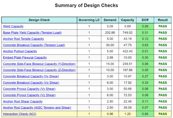
设计概要
的 SkyCiv底板设计软件 可以自动为此设计示例生成逐步计算报告. 它还提供了执行的检查及其结果比率的摘要, 一目了然地使信息易于理解. 以下是示例摘要表, 报告中包括.
SkyCiv样本报告
查看 SkyCiv 底板设计报告的详细程度和清晰度. 该报告包括所有关键的设计检查, 方程式, 并以清晰易读的格式呈现结果. 完全符合设计标准. 单击下面查看使用 SkyCiv 底板计算器生成的示例报告.
购买基板软件
单独购买基本板设计模块的完整版本,而没有任何其他SkyCiv模块. 这为您提供了底板设计的完整结果, 包括详细报告和更多功能.