总览
在 1993-1-1: 钢结构设计 (EUROCODE 3) 概述了使用极限状态方法用于建筑物的结构钢构件的设计指南. 极限状态设计需要将因子设计载荷与减少的截面和构件容量进行比较. 这些因素旨在考虑负载条件和材料特性的变化. 对于最终极限状态 (超低硫) 设计要让人满意, 以下关系必须正确:
\(超低硫 \;因素 * 负载≤减少 \;因素 * 容量)
本设计指南概述了根据 EN 设计钢结构构件的程序 1993-1-1 使用 在 1993-1-1 钢构件设计 模块.
观看我们的欧洲规范 3 钢结构设计演示
内容
材料特性
制造
在 1993-1-1 为四种类型的结构钢制造提供设计指导:
- 热轧型材: 热轧型材是通过轧机加热和轧制钢坯以达到所需形状而制造的. 示例包括 UB/UC/UBP I 型截面, T 形截面, 通道和角截面.
- 焊接截面: 焊接式 (或捏造的) 型材由多块热轧平板纵向焊接在一起形成钢型材. 定制型材通常采用焊接方式.
- 热加工型材: 热成品型材是通过在轧制之前将钢加热到超过其再结晶温度来生产的,以提高最终产品的强度. 这些截面几乎都是结构空心截面 (右侧/右侧/左侧/右侧).
- 冷弯型材: 冷成型型材是通过在室温下通过轧机压制钢坯来制造的. 冷成型可用于生产结构空心型材和较薄的开口型材. 注意 EN 1993-1-1 仅提供空心冷弯型材的指导.
钢级
欧洲和英国有众多钢种 (优势) 可用于符合 EN 的设计 1993-1-1. 针对不同类型的钢结构制造有多种欧洲材料标准:
- 在 10025: 热轧产品.
- 在 100210: 热成品结构空心型材.
- 在 10219: 冷弯焊接结构空心型材.
热轧型材 (在 10025)
热轧型钢的常用牌号和指示屈服强度概述如下:
最小屈服强度 (兆帕) |
|||||||||
|---|---|---|---|---|---|---|---|---|---|
| 年级 | ≤16毫米 | 16-40毫米 | 40-63毫米 | 63-80毫米 | 80-100毫米 | 100-150毫米 | 150-200毫米 | 200-250毫米 | 250-400毫米 |
| 小号 235 | 235 | 225 | 215 | 215 | 215 | 195 | 185 | 175 | 165 |
| 小号 275 | 275 | 265 | 255 | 245 | 235 | 225 | 215 | 205 | 195 |
| 小号 355 | 355 | 345 | 335 | 325 | 315 | 295 | 285 | 275 | 265 |
| 小号 460 | 460 | 440 | 420 | 400 | 390 | 390 | – | – | – |
最小拉伸强度 (兆帕) |
||||||
|---|---|---|---|---|---|---|
| 年级 | ≤3mm | 3-100毫米 | 100-150毫米 | 150-250毫米 | 250-400毫米 | |
| 小号 235 | 360 | 350 | 350 | 340 | 330 | |
| 小号 275 | 430 | 410 | 400 | 380 | 380 | |
| 小号 355 | 510 | 470 | 450 | 450 | 450 | |
| 小号 460 | – | 550 | 530 | – | – | |
热加工结构空心型材 (在 100210)
热成品结构空心型材的常用牌号可用性和指示性屈服强度概述如下:
最小屈服强度 (兆帕) |
||||||
|---|---|---|---|---|---|---|
| 年级 | ≤16毫米 | 16-40毫米 | 40-63毫米 | 63-80毫米 | 80-100毫米 | 100-120毫米 |
| 小号 235 H | 235 | 225 | 215 | 215 | 215 | 195 |
| 小号 275 H | 275 | 265 | 255 | 245 | 235 | 225 |
| 小号 355 H | 355 | 345 | 335 | 325 | 315 | 295 |
最小拉伸强度 (兆帕) |
|||
|---|---|---|---|
| 年级 | ≤3mm | 3-100毫米 | 100-120毫米 |
| 小号 235 H | 360 | 360 | 350 |
| 小号 275 H | 430 | 410 | 400 |
| 小号 355 H | 510 | 470 | 450 |
屈服 & 抗拉强度
材料的屈服强度是发生塑性变形的应力极限. 拉伸强度是材料在失效之前可以承受的最大应力 / 分裂. 型钢的屈服强度和抗拉强度取决于钢种和厚度. 通常,强度随着钢种的增加而增加,但随着钢厚度的增加而降低.
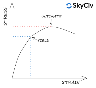
在 1993-1-1 桌子 3.1 提供了一种根据截面的等级和厚度计算其屈服强度和抗拉强度的简化方法. 更详细的材料强度计算可以参考材料相关材料标准. SkyCiv CN 1993-1-1 钢构件设计模块可以 不是 使用这种简化,而是参考相关材料标准进行材料强度计算.
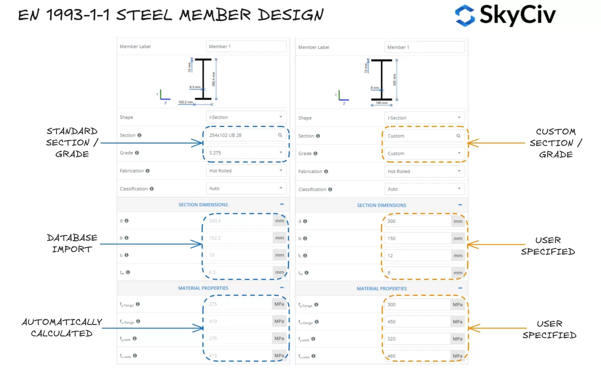
在 SkyCiv EN 中选择一个部分 1993-1-1 钢构件设计
SkyCiv 在 1993-1-1 钢构件设计 工具允许用户从 SkyCiv 数据库中选择标准钢截面或设计完全定制的截面. 程序根据所选钢种自动计算型材翼缘和腹板的屈服强度值. 如果需要,用户还可以采用自定义钢种并手动输入材料属性.
栏目分类
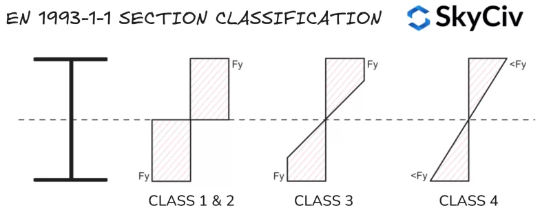
部分分类是 EN 使用的系统 1993-1-1 在达到其全部塑性能力之前确定截面对局部屈曲的敏感性. 大型细长形状通常比小型细长形状更容易受到局部屈曲的影响, 矮胖的形状. SkyCiv 在 1993-1-1 钢构件设计 工具根据应用的载荷条件自动计算标准和定制钢截面的分类. EUROCODE 3 有四个部分分类类别:
- 班级 1: 可以形成塑性铰链并产生塑性力矩/轴向阻力的部分, 这意味着整个截面在弯曲和/或压缩下可以达到其屈服强度. 班级 1 部分还具有高旋转能力. 塑料截面属性用于容量计算.
- 班级 2: 能够形成塑性铰链但旋转能力有限的部分. EUROCODE 3 款待类 1 和班级 2 几乎所有容量计算的部分都类似.
- 班级 3: 其极端压缩纤维可以达到屈服强度的部分, 但在达到塑性力矩阻力之前局部弯曲. 弹性截面属性用于容量计算.
- 班级 4: 在部分截面达到屈服强度之前,将发生局部屈曲. 减少的弹性截面属性用于容量计算.
注意, 班级 4 截面包括截面属性计算的额外复杂性 / 阻力并且不属于本指南的范围.
压缩元件
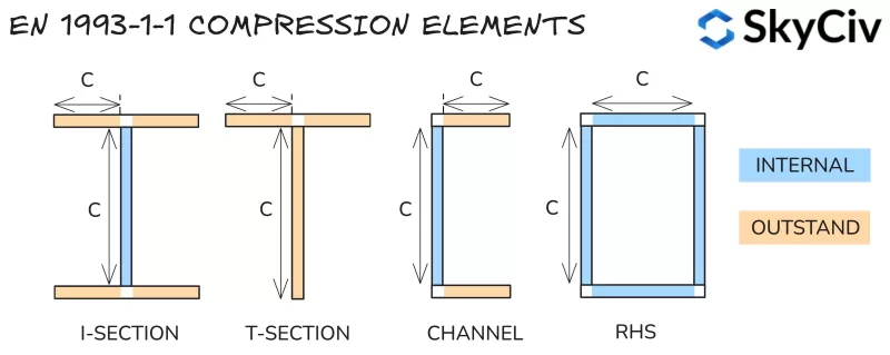
截面分类是通过将截面分解为一系列压缩单元并计算它们的长细比来确定的 (净长度与厚度的关系). 元素被分类为:
- 内部的: 抑制两端屈曲 – 即. I 型截面网.
- 杰出: 仅在一端限制屈曲 – 即. I 形截面的法兰.
计算出的长细值与表进行比较 5.2 英语 1993-1-1 来确定他们的班级. 截面的分类取其受压元件最不利的分类. 注意, 截面分类根据截面上的力而变化 (特别变化的轴向力). 每种类型负载的分类方法总结如下.
分类比率
受压缩零件
纯压缩中的元素仅使用下面概述的限制根据其细长度进行分类.
| 班级 | 内部零件 | 优秀零件 | |
| 1 | C / t≤33ε | C / t≤9ε | |
| 2 | C / t≤38e | C / t≤10ε | |
| 3 | C / t≤42ε | C / t≤14e | |
在哪里:
\(ε = sqrt{\压裂{235}{f_y}}\)
承受弯曲的零件
纯弯曲中的内部元件根据其细长程度进行分类,限制如下.
| 班级 | 内部零件 | |
| 1 | C / t≤72ε | |
| 2 | C / t≤83e | |
| 3 | C / t≤124e | |
受纯弯曲影响的突出单元根据弯矩值下的压应力和拉应力之比进行分类,导致压应力等于末端纤维处的屈服应力. 计算该比率的方法将在下面的部分中详细介绍.
受压缩零件 & 弯曲
受到组合压缩和弯曲的元件根据其压缩性进行分类 / 施加压缩载荷下的拉应力分布. 该比率由塑性应力分布的 α 符号和弹性应力分布的 ψ 符号表示.
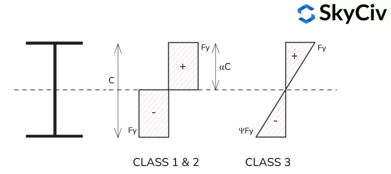
塑性应力分布
塑性应力比计算公式 (一种) 下面提供了不同形状的轮廓.
I 形截面塑性应力分布

T 形截面塑性应力分布
注意 T 形截面的短轴应力分布与 I 形截面的短轴应力分布类似.

槽钢塑性截面应力分布
请注意,T 形截面的长轴应力分布与 I 形截面的长轴应力分布类似.

RHS 塑性应力分布

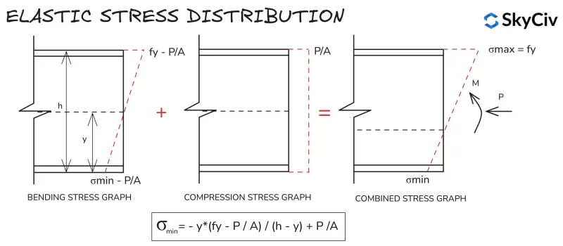
弹性应力分布
所有截面和形状的弹性应力分布计算都相似, 由于极端纤维之间的线性应力分布. 受压和弯曲作用下截面最小应力的计算公式如下所示.
SkyCiv EN 中的部分分类 1993-1-1 钢构件设计
的 天空文明一号 1993-1-1 钢构件设计 工具根据用户输入的加载自动确定标准和自定义截面的截面分类. S 级的输出示例 275, 430具有 20kN 压缩载荷的 x100x64 通道详细信息如下.
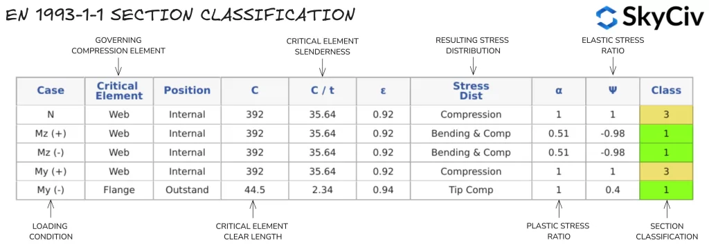
单个截面分类值用于基于所施加的轴向力和所施加的弯矩方向的所有计算. 如果构件绕两个轴施加弯矩, 采用各个方向最保守的分类. 用户还可以覆盖部分分类的自动计算并手动指定分类.
注意, 条款 5.4.1(3) 指定单对称截面 (例如 T 形截面和槽钢) 当绕非对称轴弯曲时,无法使用塑性分析进行设计. 因此,这种性质的部分会自动分配类 3.
截面电阻
弯曲
截面抗弯强度
截面弯矩能力使用 EN 计算 1993-1-1 条款 6.2.5.
\(M_{C,路} = W*f_y/γ_{莫0}\)
其中 W 是塑性截面模量 (w ^PL) 班级用 1 & 2 截面, 或弹性截面模量 (w ^他) 班级用 3 截面, F和 是材料的屈服应力,γ 是部分安全折减系数.
形状的截面模量是量化形状抗弯强度的几何特性. 塑性截面模量假设整个截面在弯曲下达到其屈服强度. 截面的塑性截面模量计算如下:
\(W_{PL} = A_{C} * y_{C} + 一个_{Ť} * y_{Ť} \)
其中AC 和一个Ť 是塑性中性轴两侧的面积 (PNA), 和yC / 和Ť 是从 PNA 到这些区域质心的距离. 注意, PNA 位置等于对称形状的几何质心位置,但会 不是 等于不对称形状的几何质心位置.
弹性截面模量假设整个截面 (形状) 在弯曲下保持弹性, 即. 截面没有任何部分超过屈服强度 (F和) 材料的. 截面的弹性截面模量计算如下:
\(W_{他} = frac{一世}{和}\)
其中 I 是面积二阶矩,y 是形状的几何质心. 不对称形状的注意事项, 设计中使用的弹性模量值是绕该轴正向和负向弯曲的较小值.
在 SkyCiv EN 中计算截面抗弯力 1993-1-1 钢构件设计
一旦计算出相关的部分分类, 该模块计算截面弯矩能力 (检查锚容量) 关于每个主轴. 相同 430x100x64 通道的结果如下例所示.

剪力
截面抗剪强度
抗剪强度使用 EN 计算 1993-1-1 条款 6.2.6. 容量计算取决于钢构件的截面分类. 班级容量 1 & 2 截面根据塑性剪切阻力计算, 而弹性剪切阻力用于 Class 3 & 4 截面.
塑料剪切阻力使用以下公式计算:
\(V_{PL,路}=A_v * (f_y / \sqrt{3}) / c_{莫0}\)
其中 Av 是截面在施加剪力方向上的剪切面积. 对于大多数截面,该面积相当于长轴方向剪力的腹板面积, 以及另一个方向的法兰面积. EN 中提供了计算剪切面积的公式 1993-1-1 条款 6.2.6(3).
使用以下关系计算弹性剪切阻力, 确保截面临界点处的剪应力小于屈服应力.
\(t_{埃德}/(f_y / (\sqrt{3 * c_{莫0}})) ≤ 1\)
该临界点的剪应力计算如下:
\(t_{埃德}=(V_{埃德} * 小号)/(一世 * Ť)\)
其中V埃德 是施加的剪切力, S 是面积的一阶矩, I 是面积截面矩,t 是临界应力位置处的厚度.
然后可以安排弹性剪切应力公式来表示阻力值 (千牛):
\(V_{他,路} = (一世 * Ť * \sqrt{3})/(小号 * f_y)\)
剪切屈曲
长的, 细长腹板在达到其弹性抗剪力之前可能会在施加的剪力作用下屈曲. 如果腹板满足以下 EN 公式,则它们容易受到剪切屈曲的影响 1993-1-1 条款 6.2.6(6):
\(H / Ť > 72 * 是/否 \)
在哪里 η 是一个通常取为的因子 1.0. 易受剪切屈曲影响的腹板必须按照第 1 节进行检查 5 或AND 1993-1-5. 注意, 剪切能力符合 EN 1993-1-5 SkyCiv EN 未涵盖 1993-1-1 工具, 但如果某个部分容易发生剪切屈曲,则会显示警告.
剪切力对弯曲的影响 & 抗压性
高剪切力会对截面的力矩和轴向阻力产生负面影响. 在英语中 1993-1-1, 通过相对于所施加的剪切强度降低截面的屈服强度来捕获这种影响 (参考条款 6.2.8 & 6.2.10). 当截面剪力为 少于 该方向塑性剪切阻力的一半, 这个影响可以忽略不计. 如果施加的剪切力大于该值, 折减屈服强度计算如下:
\(F_{和,路} = (1 -r) * f_y \)
在哪里:
\(ρ = (2 * V_{埃德} / V_{PL,路} – 1)^2)
的 天空文明一号 1993-1-1 钢构件设计 模块自动计算由于施加高剪切力而导致的屈服强度的任何降低,并在截面弯曲和压缩阻力计算中使用该降低值. 注意, 这种减少仅适用于构件的截面电阻, 不是屈曲阻力.
在 SkyCiv EN 中计算剪切阻力 1993-1-1 钢构件设计
的 天空文明一号 1993-1-1 钢构件设计 工具计算截面在两个主轴方向上的抗剪能力. 254 的剪切阻力计算结果×102 UB 28 详细如下.

压缩
截面抗压强度
在 1993-1-1 条款 6.2.4 计算压缩能力 (ñC) 同心加载的类 1,2 要么 3 部分如下:
\(N_{C,路} = A*f_y / c_{莫0}\)
其中 A 是横截面的总面积,f和 是截面的屈服强度.
在 SkyCiv EN 中计算截面抗压强度 1993-1-1 钢构件设计
的 天空文明一号 1993-1-1 钢构件设计 工具计算截面压缩阻力 (ñC,路) 适用于标准欧洲部分和自定义用户定义部分. 254 截面抗压计算结果×102 UB 28 详细如下.

张力
截面抗拉力
在 1993-1-1 条款 6.2.3 计算受拉杆件的承载力 (Nt) 为塑性抗拉强度和极限抗拉强度中的较小者:
\(N_{Ť,路} = 分钟(A*f_{和}/c_{莫0} \; ,\; 0.9*一个_{ñ}*f_u /γ_{钢底板设计欧洲规范})\)
其中 A 是截面的总面积, 一个ñ 是横截面的净面积 (总面积,不包括穿透/孔洞), F和 是个 屈服强度 该部分的, Fü 是个 拉伸 (最终的) 截面强度.
在 SkyCiv EN 中计算张力阻力 1993-1-1 钢构件设计
的 天空文明一号 1993-1-1 钢构件设计 模块假设该部分不存在明显的孔, 因此Añ 被视为等于 A. 254 截面抗拉力计算结果×102 UB 28 详细如下.

弯曲 & 轴向力
当截面施加轴向拉力或压缩力时, 应考虑该力对截面弯矩阻力的影响. EN 中概述了评估这种影响的方法 1993-1-1 条款 6.2.9 因班级而异 1 & 2 和班级 3 截面.
班级 1 & 2 栏目
通过将每个方向上的塑性力矩阻力减少与轴向力成比例的量来评估塑料截面的组合弯曲力和轴向力. 这种减小的力矩阻力由符号 M 表示ñ,路. M的计算ñ,路 因截面形状而异,并在 EN 中概述 1993-1-1 条款 6.2.9.1. 一旦计算出减少的力矩阻力, 以下标准用于评估组合的弯曲和轴向阻力:
\( (M_{和,埃德} / M_{这,路})^a + (M_{与,埃德} / M_{氮,路})^b≤ 1\)
在哪里 α和β是随截面形状变化的常数 – 请参阅 EN 1993-1-1 条款 6.2.9.1.
班级 3 栏目
弹性截面中的组合弯曲力和轴向力是使用下面详述的通用弹性应力公式来评估的:
\( N_{埃德} / N_{C,路} + M_{与,埃德} / M_{捷克,路} + M_{和,埃德} / M_{cy,路} ≤ 1\)
请注意,由于施加的剪切力而导致的屈服强度所需的任何降低都应用于计算上述公式中的截面阻力值.
抗屈曲性
弯曲
横向扭转屈曲阻力
长的, 不受约束的钢构件在达到其截面抗弯矩之前可能会因横向扭转屈曲而失效. 当截面远离其长轴朝其短轴旋转时,会发生横向扭转屈曲, 意味着施加弯曲方向的力矩阻力减小. EN 中提供了计算构件横向扭转屈曲阻力的指南 1993-1-1 条款 6.3.2.
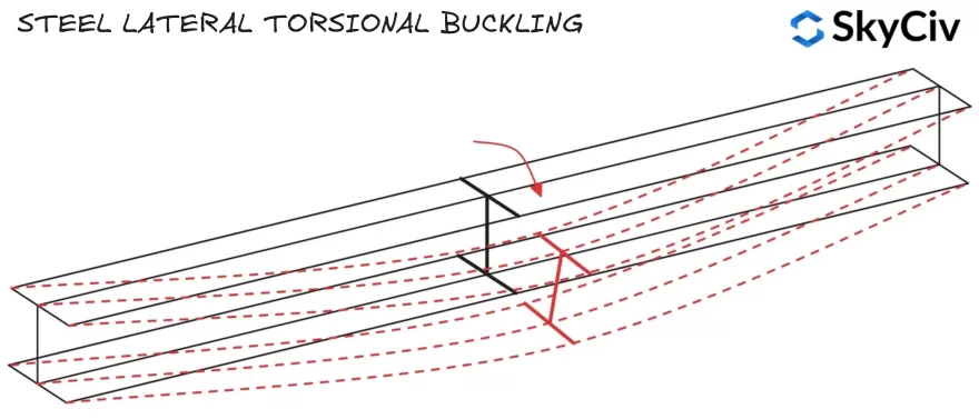
横向扭转屈曲阻力使用以下公式计算:
\(M_{b,路} = x_{LT}*W*f_y/γ_{M1}\)
其中 W 是塑性截面模量 (w ^PL) 班级用 1 & 2 截面, 或弹性截面模量 (w ^他) 班级用 3 截面. 小时LT 是横向扭转屈曲的折减系数, EN 中提供了计算该系数的指南 1993-1-1 条款 6.3.2.2 和 6.3.2.3.
压缩法兰
当压缩凸缘旋转并横向位移时,构件会发生横向扭转屈曲失效. 如果构件的压缩凸缘受到充分约束, 它不会受到横向扭转屈曲的影响 (请参阅 EN 1993-1-1 条款 6.3.2.1(2)). 垂直载荷下标准型材的压缩法兰位置如下所示.
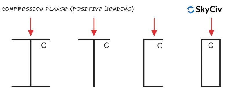
圆形空心型材 (CHS) 和方形空心截面 (SHS) 不易受到横向扭转屈曲的影响, 因为它们在两个轴上具有相等的截面力矩阻力 (这意味着横向位移和旋转不会影响构件的抗弯能力).
侧向扭转屈曲还原因子
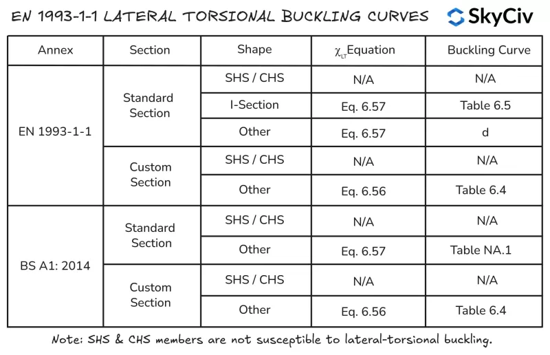
小时LT 在EN中计算 1993-1-1 使用任何一个部分 6.3.2.2 (一般案例) 或部分 6.3.2.3 (滚动部分或等效焊接部分). 部分 6.3.2.3 适用于所有人 “标准” 部分和形状 (包括空心部分) 和他们的焊接等效物. 部分 6.3.2.2 适用于任何不属于前者类别的部分, 包括定制的制造和建筑部分.
部分 6.3.2.2 使用等式 6.56 用于计算横向扭转屈曲还原fact0rχ的LT 而部分 6.3.2.3 使用等式 6.57. 的 天空文明一号 1993-1-1 钢构件设计 模块遵循以下概述以应用方程的逻辑 6.56 和 6.57.
短轴弯曲抗屈曲性能
绕其短轴弯曲的构件的弯曲能力等于绕该轴的短轴截面阻力. 短轴截面容量是截面围绕任何轴可以达到的最小容量, 因此该构件不能从该轴旋转到不利的方向.
计算 EN 中的构件抗弯强度 1993-1-1 钢构件设计
的 天空文明一号 1993-1-1 钢构件设计 工具计算根据 EN 进行横向扭转阻力计算 1993-1-1 条款 6.3.2.2 和条款 6.3.2.3, 取决于截面形状和应用的国家附件. 用户还可以选择将成员指定为具有 “连续扭转约束” 这将自动跳过所有横向扭转屈曲检查. 5000mm长254的横向扭转屈曲阻力计算×102 UB 28 详细如下.

压缩
抗弯屈曲性
构件的抗压屈曲性能还受到其长度和横向刚度的影响. 无拘无束, 较长的构件可能会因截面前的弯曲屈曲而失效 (壁球) 容量已达到. 在 1993-1-1 条款 6.3.1.3 提供计算构件抗弯屈曲阻力的指南 1, 2 & 3 交叉区域:
\(N_{b,路} = x*A*f_y/ γ_{M1}\)
在哪里 χ 是弯曲屈曲的折减系数. EN 中提供了计算该系数的指南 1993-1-1 条款 6.3.1.3. F必须检查两个轴的词汇能力,以找到成员的控制值.
计算 EN 中的抗弯屈曲阻力 1993-1-1 钢构件设计
的 天空文明一号 1993-1-1 钢构件设计 工具根据用户指定的约束长度和有效长度系数计算两个主轴的弯曲屈曲阻力. 254 的抗弯屈曲性能×102 UB 28 Z轴和Y轴无限制长度分别为6000mm和5000mm (分别) 详细如下.

抗扭转弯曲屈曲性
开放横截面也容易受到扭转弯曲屈曲的影响, 它可以小于构件的抗弯屈曲阻力. 圆形空心型材 (CHS) 和方形空心截面 (SHS) 构件不易受到扭转弯曲屈曲的影响. 在 1993-1-1 条款 6.3.1.4 提供计算构件扭转弯曲屈曲阻力的指导:
\(N_{乙T,路} = χ_T*A*f_y/ γ_{M1}\)
在哪里 小时LT 是扭转弯曲屈曲的折减因子. EN 中提供了计算该系数的指南 1993-1-1 条款 6.3.1.3. F必须检查两个轴的词汇能力,以找到成员的控制值.
计算 EN 中的扭转弯曲屈曲阻力 1993-1-1 钢构件设计
的 天空文明一号 1993-1-1 钢构件设计工具 根据 EN 计算适用的开放和封闭截面的扭转弯曲屈曲阻力 1993-1-1 条款 6.3.1.4 基于用户指定的长轴压缩约束长度. 254 的扭转弯曲屈曲阻力×102 UB 28 无限制长度6000mm详述如下.

SkyCiv 结构设计软件
SkyCiv 提供广泛的结构分析和工程设计软件, 包含:
-
- EUROCODE 3 钢设计
- EUROCODE 9 铝设计
- EUROCODE 3 檩条设计
- EUROCODE 3 螺栓组计算器
- EUROCODE 3 焊缝组计算器
- EUROCODE 2 开发长度计算器
- EUROCODE 2 搭接长度计算器
- EUROCODE 5 木材设计计算器
- EUROCODE 3 脚手架设计计算器
软件开发师 | 结构工程师
ng (民用), 工程学士学位 (软件)
领英


