Su guía para el software SkyCiv: tutoriales, guías prácticas y artículos técnicos
Exportar a 3D estructural
Modele y exporte geometría estructural directamente a S3D
CloudCAD le permite crear geometría estructural directamente dentro de CAD y exportarla a Structural 3D (S3D). Asignando datos estructurales a puntos, líneas y regiones de sombreado, CloudCAD entiende cómo se debe interpretar cada elemento durante la exportación. Esta guía cubre el flujo de trabajo completo., desde la asignación de propiedades estructurales hasta la revisión y exportación de su modelo.
Tipos de geometría estructural
CloudCAD utiliza diferentes tipos de geometría para representar diferentes elementos estructurales durante la exportación:
Tipo de geometría
Objetos estructurales
Agujas
Columnas o Soportes
Líneas
Vigas
Regiones de sombreado
Placas
Exportar flujo de trabajo
Antes de exportar a S3D, La geometría estructural sigue un flujo de trabajo simple de cuatro pasos.:
Paso 1
Geometría
Al arrastrar de izquierda a derecha, se seleccionará todo lo que toque el cuadro de selección.
Paso 2
Datos estructurales
Al arrastrar de izquierda a derecha, se seleccionará todo lo que toque el cuadro de selección.
Paso 3
Revisar
Al arrastrar de izquierda a derecha, se seleccionará todo lo que toque el cuadro de selección.
Paso 4
Exportar a S3D
Antes de poder exportar la geometría a S3D, CloudCAD necesita entender cómo debe comportarse estructuralmente cada elemento. Esto se logra asignando propiedades estructurales a los puntos., líneas y regiones de sombreado, permitiendo su exportación como soportes, columnas, vigas y placas dentro del modelo final.
Modo estructural
Controlar cómo se comporta la geometría durante la exportación estructural
El modo estructural está habilitado de forma predeterminada, lo que significa que a la geometría recién creada se le asignan automáticamente propiedades estructurales y se incluyen durante la exportación.
CONTROLES DEL MODO ESTRUCTURAL
Utiliza el Alternar modo estructural en la esquina inferior derecha de la pantalla.
Presione el acceso directo predeterminado T3.
Nota: Cuando el modo estructural está deshabilitado, La geometría se comporta solo como geometría de dibujo y no se incluirá al exportar a S3D..
Asignación de apoyos
Aplique restricciones de soporte a puntos de su modelo.
Los soportes definen cómo se restringe una estructura y solo se pueden aplicar a puntos en su modelo..
PASO A PASO
Resalte los puntos deseados.
Haga clic derecho en los puntos seleccionados.
Seleccione Asignar fijación de soporte.
Elija un tipo de soporte, como Fijado o Fijo.
Si Otro está seleccionado, ingrese los códigos de fijación personalizados.
Nota: Los soportes sólo se pueden asignar a puntos., no líneas ni regiones de sombreado.
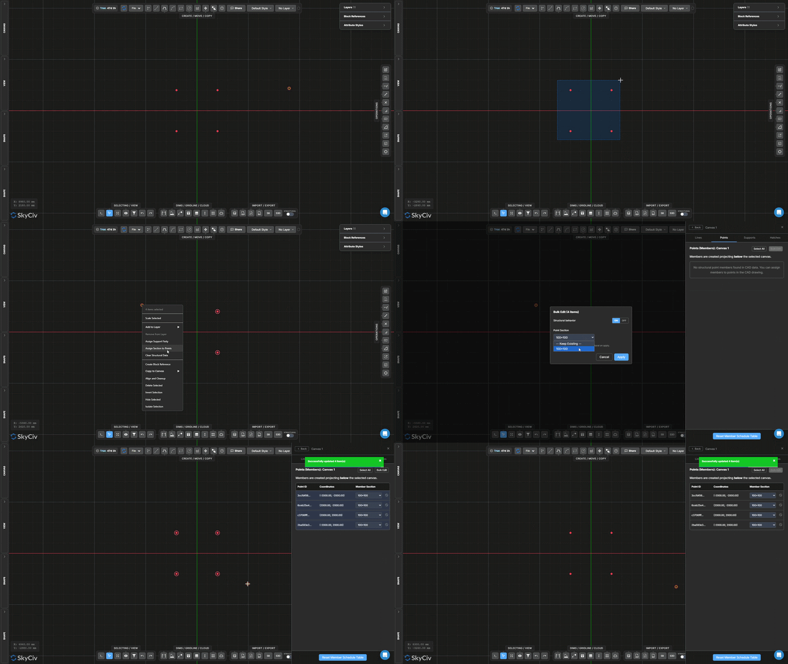
Asignar secciones a puntos (Columnas)
Definir puntos como columnas estructurales
Los datos estructurales se pueden asignar a puntos para que se reconozcan como columnas durante la exportación..
PASO A PASO
Resalte los puntos requeridos.
Haga clic derecho en los puntos seleccionados.
Seleccione Asignar secciones a puntos.
Permitir Datos estructurales.
Aplicar la sección requerida.
Nota: Los puntos asignados a secciones estructurales se exportarán como columnas.. Las columnas se generan proyectando debajo del lienzo seleccionado., permitiéndoles conectarse entre elevaciones en modelos de lienzos múltiples.
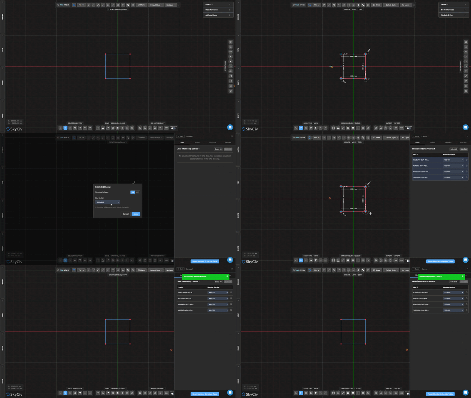
Asignar secciones a líneas (Vigas)
Definir líneas como miembros de vigas estructurales.
Los datos estructurales se pueden asignar a líneas para que se reconozcan como vigas durante la exportación..
PASO A PASO
Seleccione las líneas requeridas.
Haga clic derecho.
Seleccione Asignar secciones a líneas.
Permitir Comportamiento estructural.
Aplicar la sección requerida.
Nota: Las líneas asignadas a secciones estructurales se exportarán como miembros de viga en S3D.
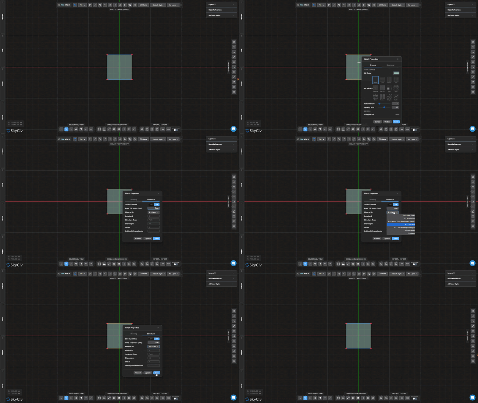
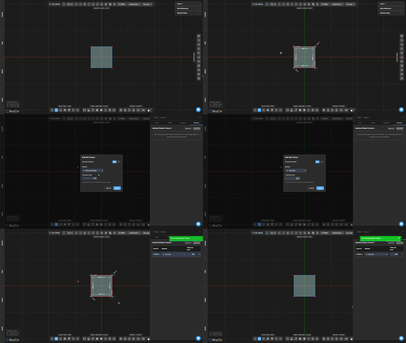
Asignación de propiedades de placa
Definir regiones de sombreado como placas estructurales, losas, o paredes
Las regiones de sombreado se denominan placas porque representan elementos estructurales basados en la superficie, como losas y muros..
PASO A PASO
Seleccione las regiones de sombreado requeridas.
Haga clic derecho.
Seleccione Asignar propiedades de placa.
Permitir Comportamiento estructural.
Seleccione un material.
Introduzca un espesor de placa.
Nota: Las propiedades de la placa se pueden modificar en cualquier momento haciendo doble clic en una región de sombreado existente y seleccionando el Estructural lengüeta.
Revisión de datos estructurales
Verifique la información estructural antes de exportar a S3D
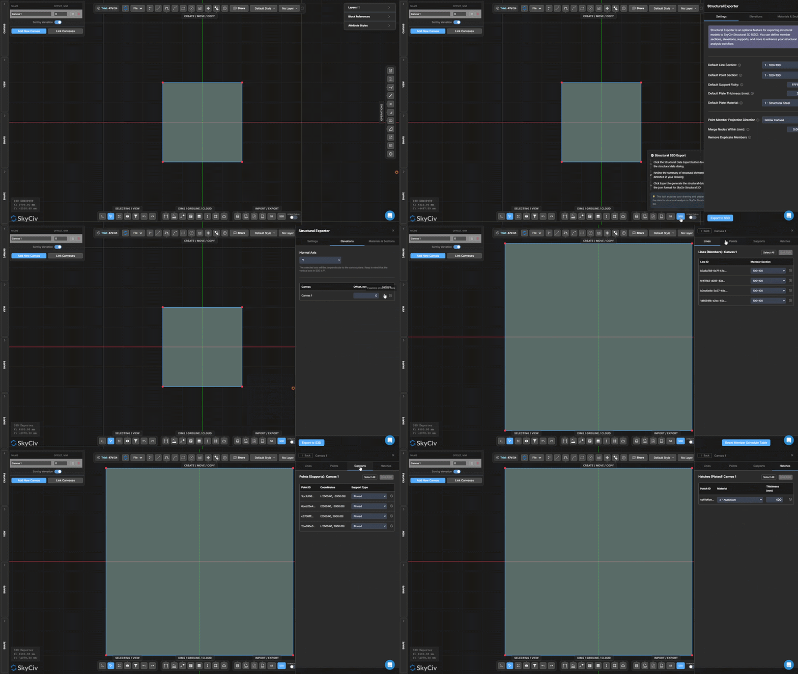
Antes de exportar a S3D, Se recomienda revisar todos los datos estructurales asignados para garantizar que el modelo se haya configurado correctamente..
PASO A PASO
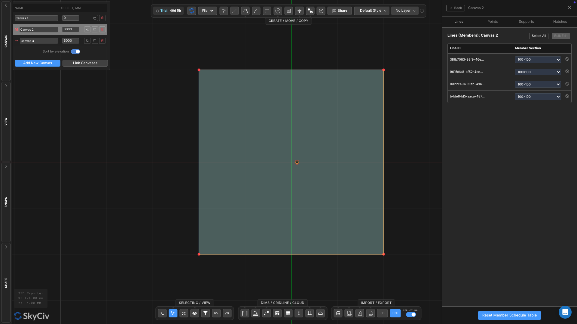
tenemos miembros S3D botón en la esquina inferior derecha de la pantalla.
Navega hasta el Elevaciones lengüeta.
tenemos miembros Examinar datos estructurales , (icono de lupa).
TABLAS DE DATOS DISPONIBLES
Objeto estructural
Información mostrada
Suportes
Fijaciones de soporte asignadas
Columnas
Secciones asignadas
Vigas
Secciones asignadas
Placas
Información de material y espesor.
Nota: Al seleccionar un elemento dentro de cualquier tabla de datos estructurales, se resaltará automáticamente el miembro correspondiente en el lienzo., facilitando la localización y revisión de objetos específicos.
Mejores prácticas: Revisar los datos estructurales antes de exportar es la forma más rápida de identificar soportes faltantes, secciones incorrectas, o propiedades de placa incompletas y garantizar que el modelo esté listo para exportar.
Exportar a S3D
Transfiera su modelo estructural directamente a S3D
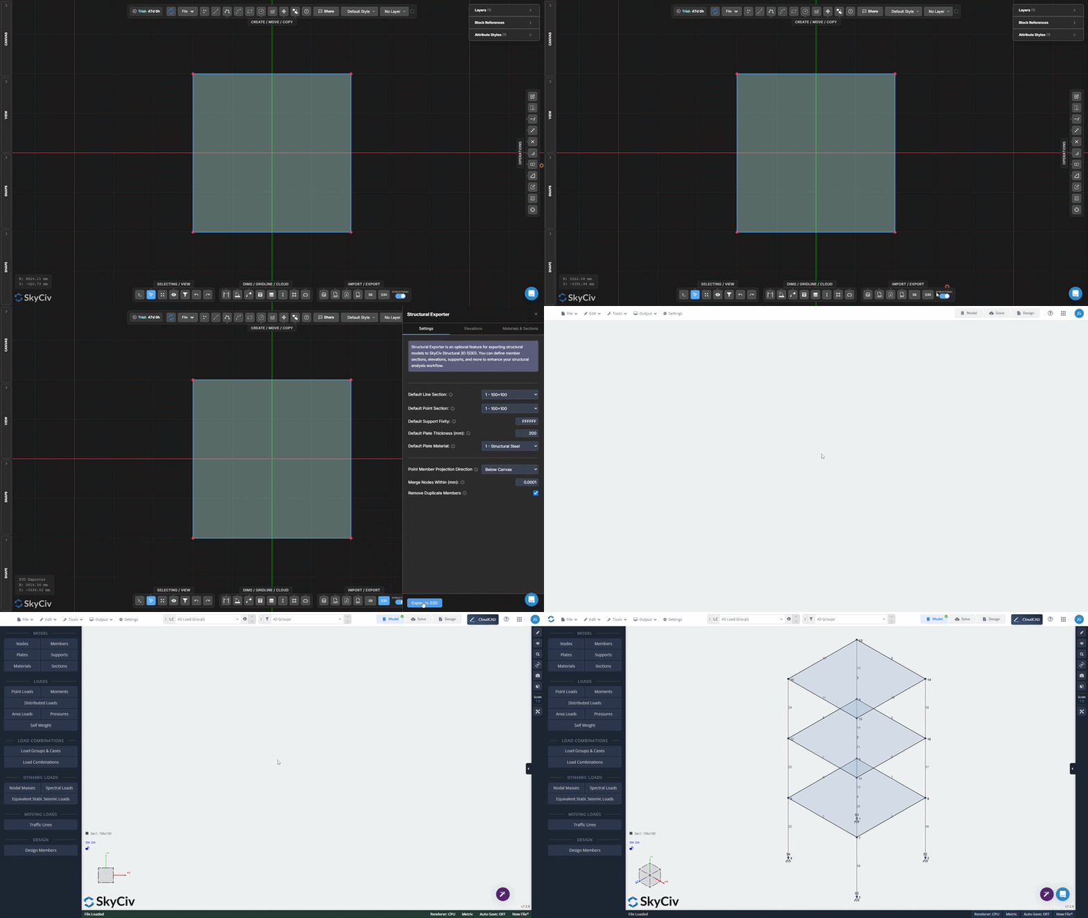
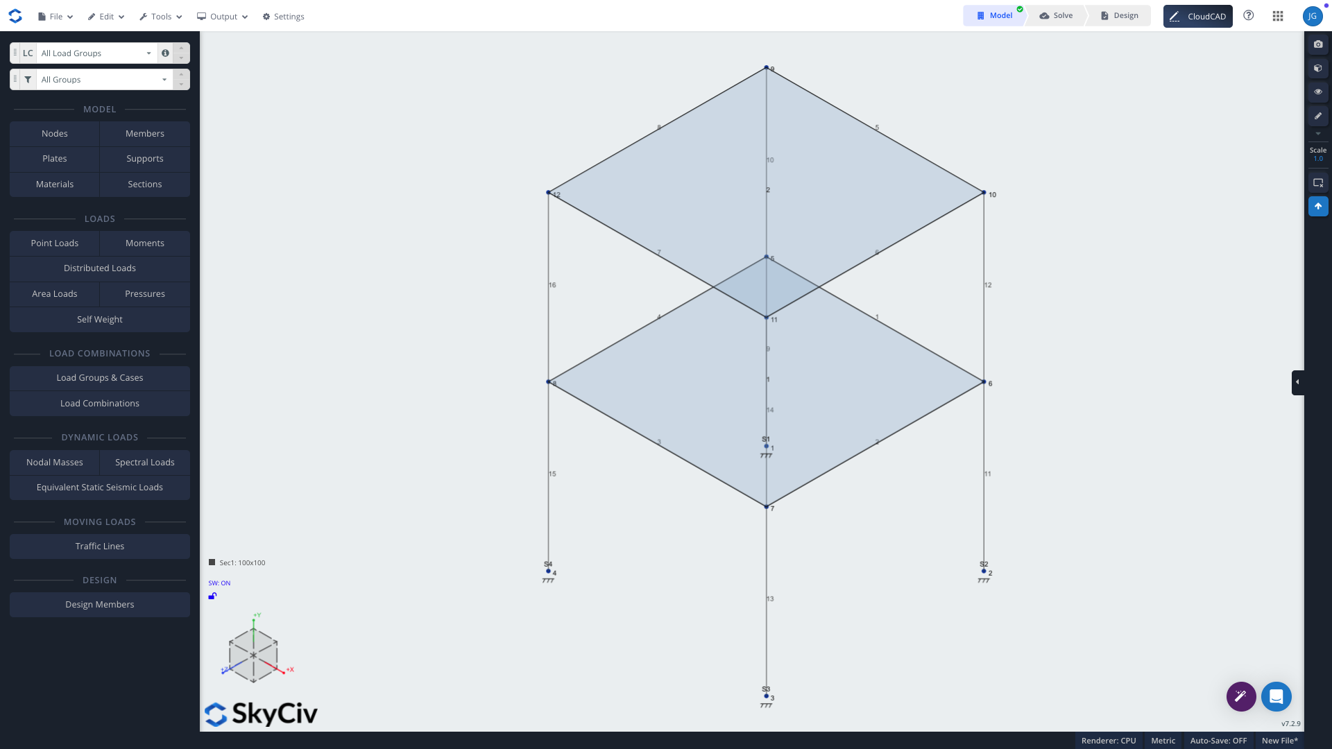
Una vez que todos los datos estructurales hayan sido asignados y revisados, el modelo está listo para exportarse a S3D para cargarlo, análisis preciso, y diseño.
PASO A PASO
Abre el Exportador Estructural.
Revisar la configuración de exportación.
Seleccione el apropiado Eje normal (X, Y, o Z).
Seleccione Exportar a S3D.
Nota: El eje normal define la dirección vertical del modelo exportado.. Asegúrese de seleccionar el eje correcto antes de exportar.
¿Qué pasa después?? Después de la exportación, el modelo se abrirá en S3D donde se carga, combinaciones de carga, configuración de análisis, y se pueden aplicar controles de diseño.
Ejemplo resuelto
El siguiente ejemplo demuestra el flujo de trabajo completo para crear un modelo estructural de varios niveles en CloudCAD y exportarlo directamente a S3D.
Comenzando con una geometría de dibujo simple, Crearemos múltiples niveles usando el sistema Master and Child Canvas., asignar datos estructurales, revisar el modelo generado y exportarlo para análisis estructural.
Paso 1 – Crear ubicaciones de columnas en la planta baja
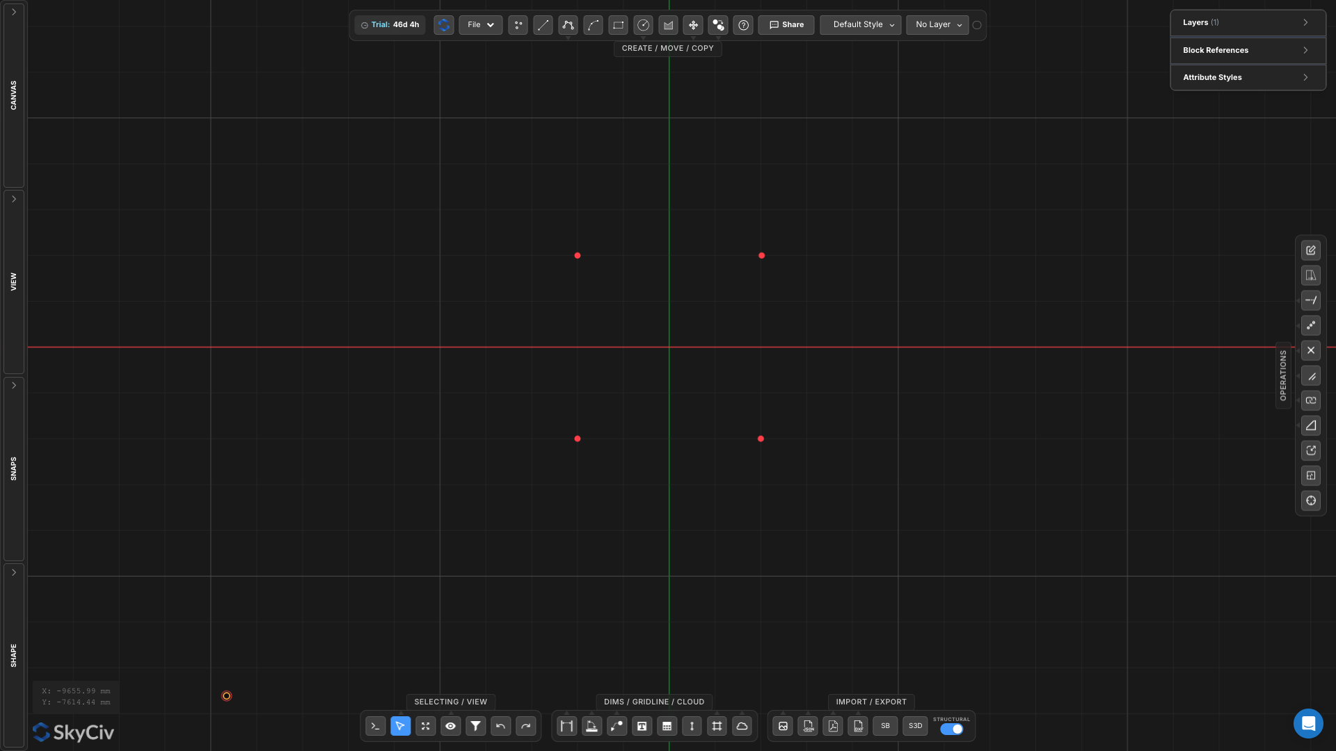
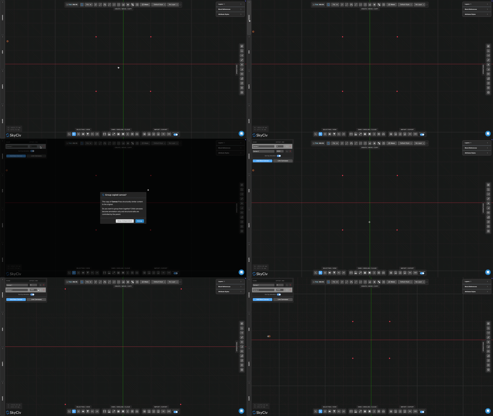
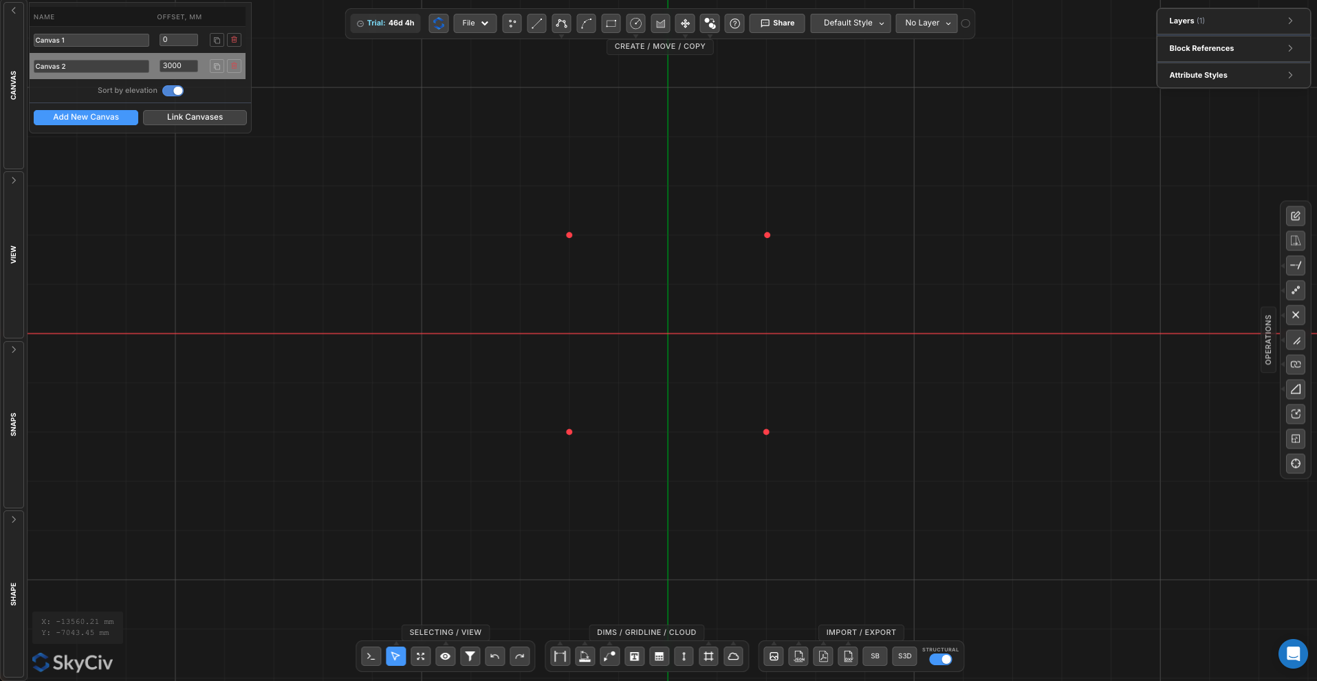
Comience creando cuatro puntos en Canvas. 1.
Estos puntos representan las ubicaciones de las columnas de la estructura..
En este momento no se han asignado datos estructurales.. Los puntos simplemente definen dónde se proyectarán las columnas desde el lienzo de arriba..
Paso 2 – Crea el lienzo del primer piso
Para crear el nivel del primer piso., lienzo duplicado 1.
Duplicar el lienzo copia la geometría existente, asegurar que las ubicaciones de las columnas permanezcan alineadas entre niveles.
Cuando se le solicite, elegir Manténgase independiente en lugar de crear un grupo de lienzo.
El lienzo duplicado ahora puede contener una geometría diferente a la del lienzo original.. Esto es importante porque los lienzos agrupados comparten geometría estructural., haciéndolos inadecuados cuando cada nivel requiere una disposición estructural diferente.
En esta etapa:
Lienzo 1 contiene las ubicaciones de las columnas de la planta baja.
Lienzo 2 contiene ubicaciones de columnas coincidentes en el nivel del primer piso.
Ambos lienzos permanecen independientes y se pueden modificar por separado..
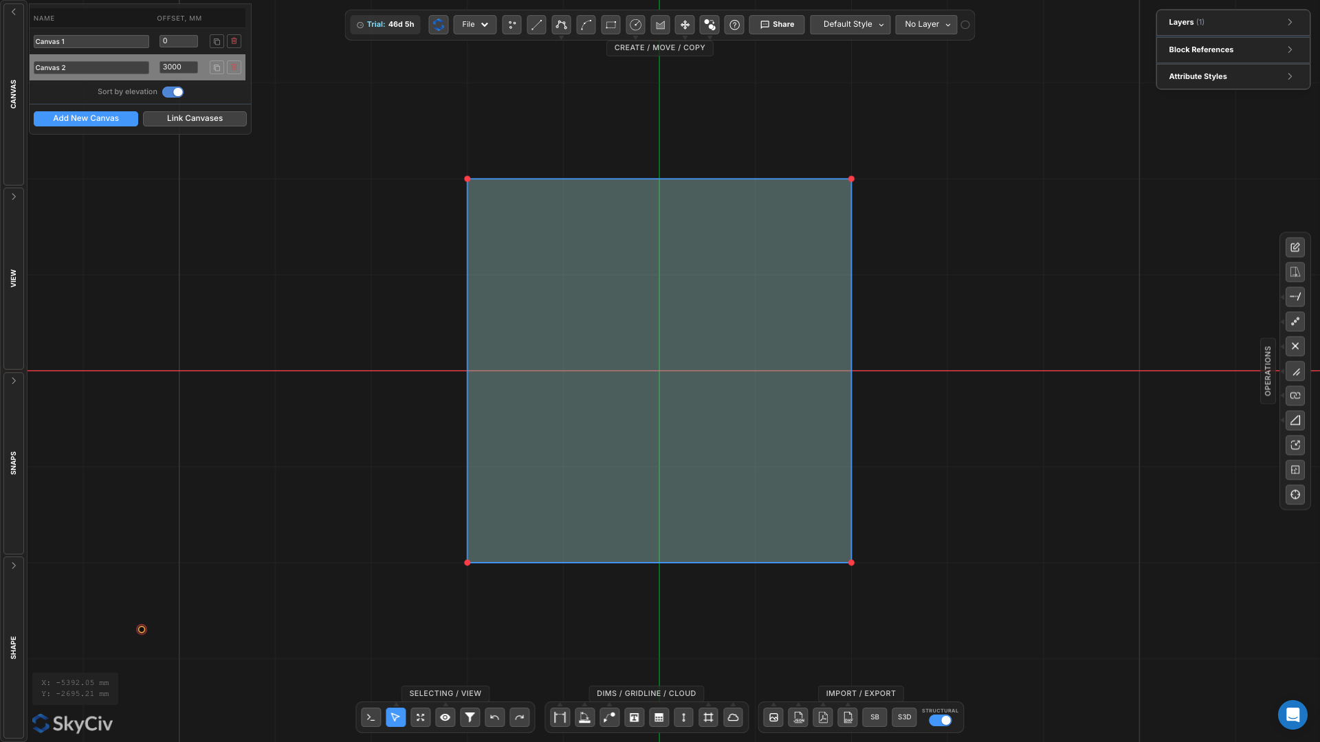
Esto configura el siguiente paso donde se dibuja la geometría de la viga y la placa en Canvas. 2.
Paso 3 – Crear el diseño del marco del piso
Sobre lienzo 2:
Dibuje líneas de vigas perimetrales que conecten las ubicaciones de las columnas.
Cree una región de sombreado que represente la losa del piso.
Paso 4 – Crear un grupo de lienzo maestro y secundario
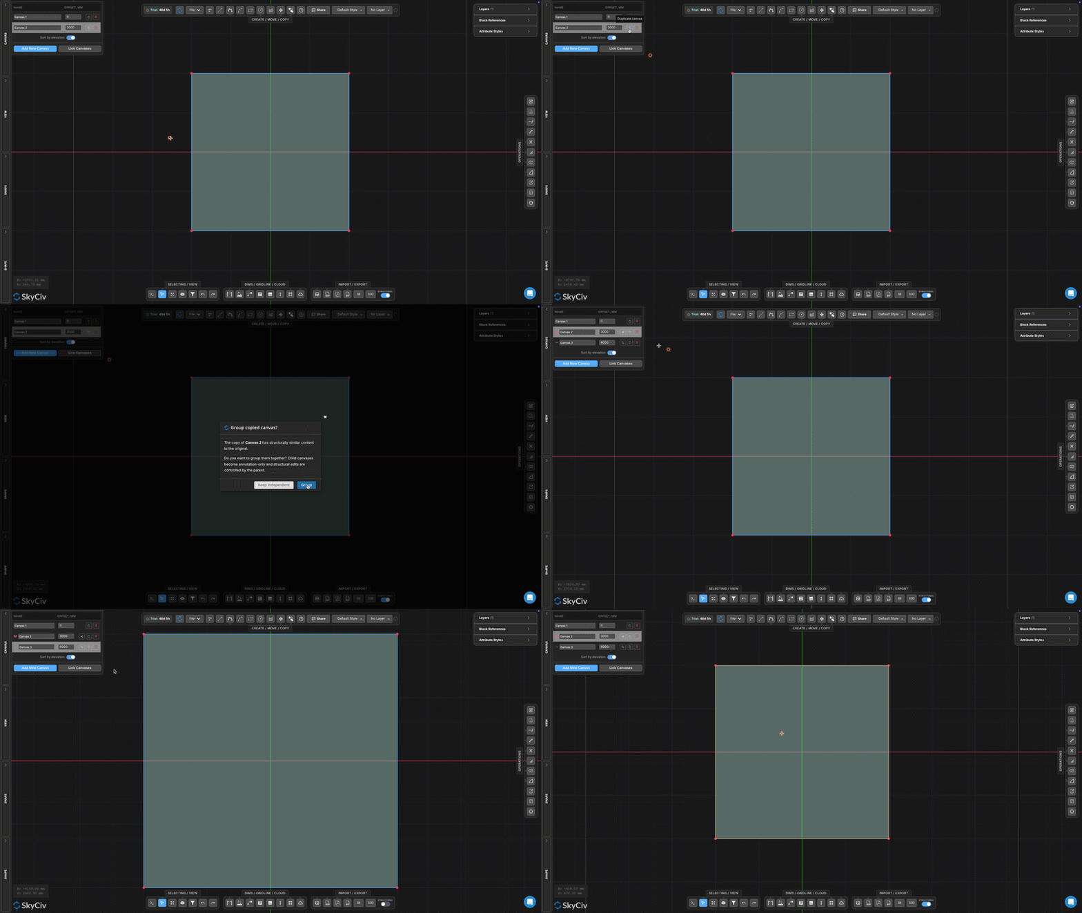
Lienzo duplicado 2 para crear un tercer lienzo.
Cuando se le solicite, elegir Lienzo grupal.
Lienzo 2 se convertirá en el Lienzo maestro y lienzo 3 se convertirá en un Lienzo Infantil.
El lienzo secundario hereda automáticamente la geometría estructural y los datos estructurales asignados al lienzo maestro.. Cualquier cambio estructural realizado en el lienzo maestro se puede propagar a todos los lienzos secundarios vinculados., haciendo que este flujo de trabajo sea ideal para diseños de piso repetidos en estructuras de varios pisos.
En este ejemplo, Se utilizará la misma disposición de vigas y placas en ambos niveles elevados., permitiendo que la estructura se modele una vez y se reutilice en varios pisos.
Paso 5 – Asignar datos estructurales al maestro
Con Geometría completa, Se pueden aplicar propiedades estructurales.
Presione el comando A para seleccionar toda la geometría en el lienzo maestro.
Haga clic derecho y seleccione Asignar secciones a puntos.
Aplicar la sección estructural predeterminada.
Haga clic derecho y seleccione Asignar secciones a líneas.
Aplicar la sección estructural predeterminada.
Seleccione la región del sombreado.
Haga clic derecho y seleccione Asignar propiedades de placa.
Establecer el material en Hormigón.
Introduzca un espesor de placa de 300 mm.
Porque lienzo 3 está vinculado como un lienzo secundario, toda la geometría estructural y las propiedades asignadas se heredan automáticamente del Master Canvas. Esto permite gestionar diseños de pisos repetidos desde una única ubicación mientras se mantienen datos estructurales consistentes en múltiples niveles..
Paso 6 – Asignar soportes
Volver al lienzo 1 y asignar soportes a las ubicaciones de las columnas.
Seleccionar todos los puntos de la columna
Haga clic derecho
Seleccione Asignar fijación de soporte
Elegir Fijo
Las columnas exportadas desde los niveles superiores se proyectarán hacia estas ubicaciones de soporte..
Paso 7 – Revisar datos estructurales
Antes de exportar, revisar el modelo estructural generado.