Espero que hayas pasado por nuestro blog anterior. Ejemplo de diseño compuesto AS2327 que da una idea general sobre el modelo de diseño compuesto. Si aún no lo has hecho, Te pediría que lo revises y vuelvas aquí.. Para los que han visitado el mismo, por favor sigue leyendo.
Para hoy, hagamos un recorrido para comprender el proceso de diseño de una viga compuesta y los cálculos paso a paso obtenidos con el programa de diseño de vigas compuestas de SkyCiv.
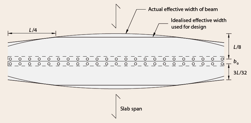
Determinación de la sección eficaz de la porción de hormigón (ancho efectivo)
El primer paso para definir la sección transversal de una viga mixta es acceder al ancho del ala de hormigón disponible para actuar de forma mixta con la sección de acero.. Los anchos efectivos se expresan en relación con la luz de la viga. El valor constante del ancho efectivo se toma como L/4.
Determinación de la sección de acero de porción efectiva:
Cuando la viga de acero bajo compresión, su sección se pandeará si es poco compacta o esbelta. En este caso, en el diseño solo se considera el área efectiva. Para esto, la sección debe clasificarse en la categoría a saber. Compacto/No compacto/Esbelto. 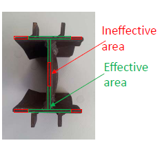
Las secciones compactas son preferibles a las secciones no compactas. En caso de que alguno de los elementos caiga en la categoría de sección No Compacta, su porción efectiva debe ser considerada en cálculos posteriores mediante el cálculo de anchos reducidos. Para secciones compactas, se supone que toda la sección transversal es efectiva sin ninguna reducción. Sección transversal que tiene esbelto elemento deberá no ser usado. 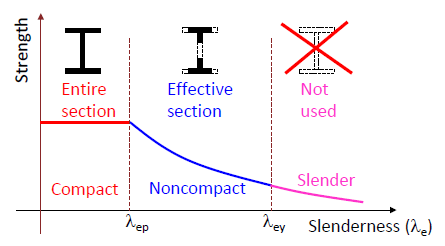
El ancho efectivo de la placa de acero se determinará de acuerdo con AS4100, lo que conduce al cálculo de la esbeltez del elemento debido al pandeo local.. La esbeltez del elemento para pandeo local se comprobará como sigue: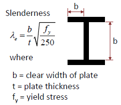
Diseño de viga para Fuerza
El diseño de la viga compuesta para los criterios de resistencia implica el cálculo de la capacidad de momento. El módulo es capaz de evaluar la capacidad de momento de pandeo de una viga como un caso de viga simplemente apoyada.
-
- La capacidad de momento se calcula considerando conexión de cortante total (FSC) Es decir. β=1.0
- Como parte de FSC, 3 Diferentes casos para el Eje Neutro Plástico (ANP) posicionamiento se consideran para la evaluación de la capacidad de momento.
- Cuando la losa de hormigón es más resistente que las vigas de acero, la ANP estará dentro de la forjado como se muestra en la figura (1). Para este caso, la resistencia última a la flexión se determina a partir de una simple fuerza de par.
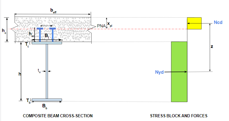 Fig(1) : PNA se encuentra en losa de hormigón
-
- Cuando la viga de acero es más resistente que la losa de hormigón, el eje neutral de plástico se ubicará dentro de la viga de acero como se muestra en la Fig. (2). Para este caso, la fuerza del momento se puede obtener sumando los momentos sobre el centroide de la fuerza de tensión. Puede haber dos subcasos en esta categoría, a saber. PNA se encuentra dentro del ala superior de la viga de acero Fig (2-a)o PNA se encuentra en la web Fig (2-b).

- Cuando la viga de acero es más resistente que la losa de hormigón, el eje neutral de plástico se ubicará dentro de la viga de acero como se muestra en la Fig. (2). Para este caso, la fuerza del momento se puede obtener sumando los momentos sobre el centroide de la fuerza de tensión. Puede haber dos subcasos en esta categoría, a saber. PNA se encuentra dentro del ala superior de la viga de acero Fig (2-a)o PNA se encuentra en la web Fig (2-b).
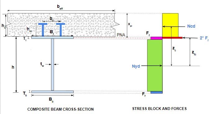
Fig(2-a) : PNA se encuentra en el ala superior de la viga de acero 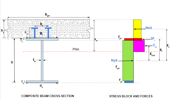 Fig(2-b) : PNA se encuentra en el ala superior de la viga de acero
-
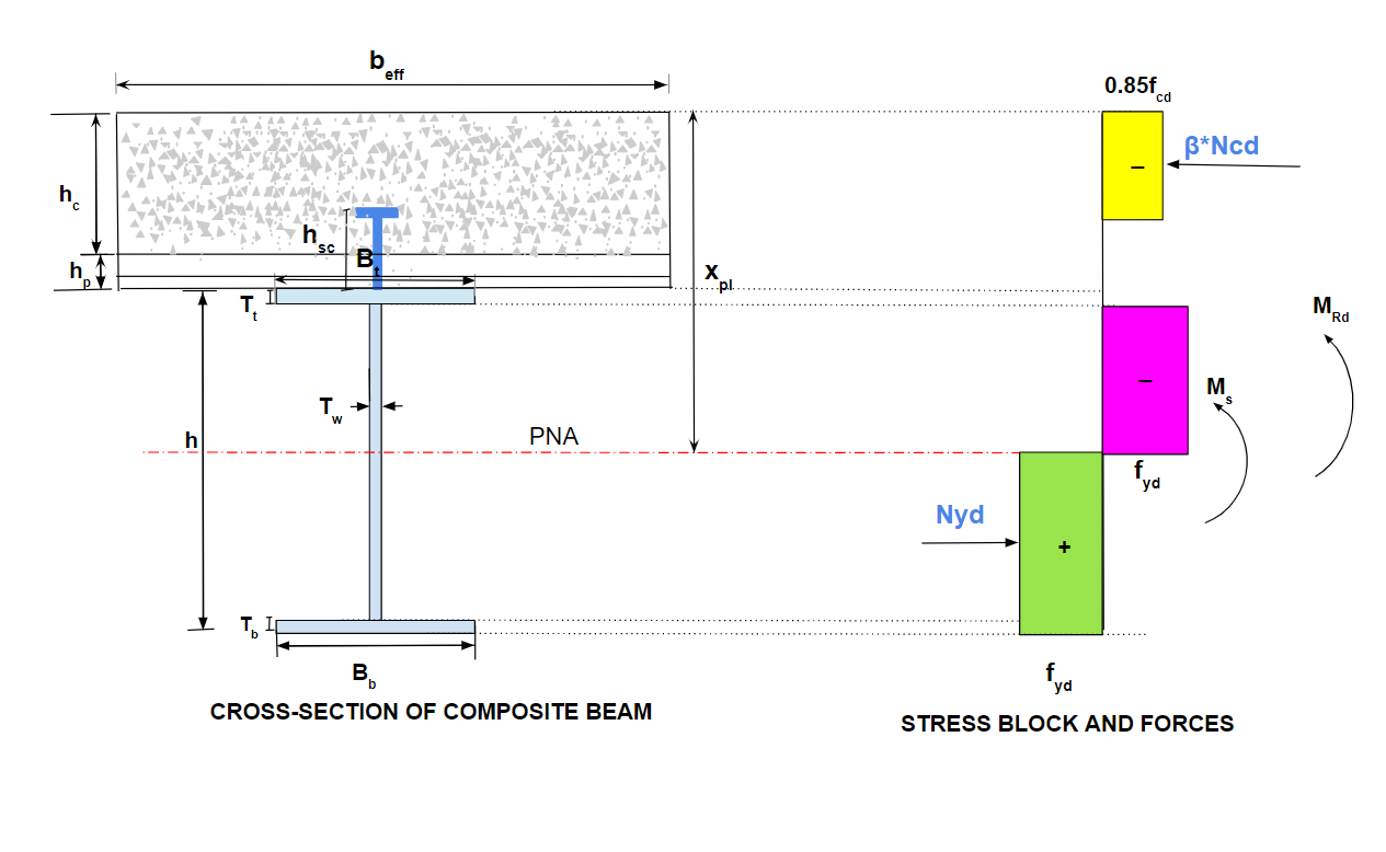
- Cuando hay una plataforma de metal corrugado debajo de la losa de concreto, el momento de resistencia para FSC se calcula de manera similar considerando 3 posibilidades de puesto PNA. Las orientaciones de la plataforma también se tienen en cuenta al evaluar el momento de resistencia, a saber. la plataforma es paralela al tramo de la viga (θ=0), la cubierta es perpendicular al tramo de la viga (θ=90) o cualquier ángulo formado por la cubierta con luz de viga en el rango de 0 a 90(0<θ<90)
- Además de esto, la capacidad Momento se calcula considerando conexión a cortante parcial (PSC) Es decir. por valor de β=0.1 a 0.9

- El programa también estima la capacidad de momento de solo la sección de la viga de acero, es decir. el caso donde NO HAY ACCIÓN COMPUESTA. Este es el caso donde β=0 y por lo tanto, la losa de hormigón en la sección transversal no juega ningún papel en el diseño de flexión. Este puede ser el caso durante la construcción por una duración muy corta..
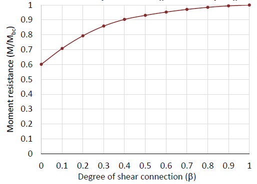
- Según lo prescrito en AS:2327, la relación entre el grado de conexión a cortante si y el momento de la relación de resistencia (Es decir. relación del momento correspondiente al valor específico de β al momento correspondiente a β=1) para varios valores de β que van desde 0 a 1.0 se grafican.
- El usuario puede hacerse una idea de la capacidad de momento para cierto grado de conexión de cortante para las dimensiones de la sección transversal y los conectores de cortante dados.. El número de ensayos para conectores de corte en términos de tamaño y espaciado se puede realizar usando el programa y el gráfico.
Diseño de Viga para Cortante
-
- La comprobación de cortante se calcula tanto para cortante vertical como para cortante longitudinal.
- El cortante longitudinal se evalúa en la interfaz entre la losa de hormigón y la viga de acero..
- Para el tamaño y el espacio dados (o números) de conectores de cortante, se evalúa la capacidad de carga de cortante longitudinal. Así, el usuario obtiene el valor proporcionado de si para la conexión a cortante. El valor mínimo requerido de β es calculado por el programa según Cl. 3.5.8.3. El valor requerido de β para el momento de resistencia deseado se puede obtener del gráfico anterior.
- La evaluación anterior puede guiar al usuario sobre la optimización en el caso de conectores de corte basados en el criterio de resistencia al corte longitudinal..
- El cortante vertical resistido por la sección transversal dada se evalúa con base en la contribución de la losa (según AS2327), acero estructural (según AS4100) y los conectores de cortante (según AS2327).
- El usuario puede especificar si considerar o ignorar la contribución de corte de la losa de hormigón en los cálculos de capacidad de corte.
- El programa admite dos tipos de conectores de corte, a saber. pernos de seguridad y pernos estructurales.
- La salida del programa proporciona la indicación al usuario sobre las disposiciones detalladas de los conectores de corte, a saber. menos dia. de conector, espacio mínimo y máximo permitido, distancias al borde, número de filas, etc..
Diseño de Viga para Servicio
-
- Los cálculos de servicio implican la estimación de la deflexión en los siguientes casos:
- etapa de construccion (Solo viga de acero)
- Efectos a corto plazo de la etapa de servicio (sección compuesta)
- efectos a largo plazo de la etapa de servicio debido a la contracción (sección compuesta)
- efectos a largo plazo de la etapa de servicio debido a la fluencia (sección compuesta)
- El programa es capaz de calcular la deflexión para los casos anteriores en base a la teoría de la sección SIN AGRIETADAS o la sección AGRIETADA. La elección se le da al usuario para especificar el tipo de sección a saber. agrietado o no agrietado.
- En caso de análisis basado en sección no fisurada, El programa evalúa el área transformada del hormigón en términos de acero estructural y, posteriormente, las otras propiedades de la sección que se necesitan para el cálculo de la deflexión..
- El análisis de la sección fisurada se basa en la suposición de que el hormigón se ignora en la sección compuesta.
- La deflexión total se calcula para los casos anteriores, que se considera como la deflexión permisible para la sección transversal dada y se compara con la deflexión real.
- Los cálculos de servicio implican la estimación de la deflexión en los siguientes casos:
Esté atento a este espacio para el próximo blog sobre un tutorial similar para las columnas compuestas.