¿Qué es una carga excéntrica??
Una carga excéntrica es cualquier carga que no aplicado al centroide del miembro. En análisis de elementos finitos, cargas puntuales, cargas distribuidas, y generalmente se aplican otras fuerzas al centroide de la sección (Es decir. el centro geométrico de la sección). sin embargo, En ciertos escenarios es posible que desees aplicar una fuerza descentrada. – por ejemplo, aplicar una carga al ala de una viga en I, en lugar de la web. Suponiendo que se trata de una carga lateral, Esto creará una fuerza de torsión y un comportamiento de carga general diferente en el miembro..
Cómo aplicar cargas excéntricas a un modelo
Aquí le mostraremos un ejemplo de cómo puede utilizar Enlaces rígidos aplicar una carga tan excéntrica. Usando enlaces rígidos, podemos transferir la carga desde el centroide del miembro a una ubicación diferente. Enlaces rígidos Son extremadamente útiles para este tipo de trabajo., ya que calcula automáticamente el momento resultante y otras fuerzas de un lugar a otro.
Dirigirse a S3D y crear un nuevo modelo. próximo, seleccione la herramienta pluma en el panel derecho o tocando V . Haga clic una vez para colocar el primer nodo en el origen, luego dibuje hacia arriba unos 2 m (6.5ft) para crear una columna.
Abajo en la esquina por el sistema de coordenadas., hacer clic Sec1: No definida, luego en el panel izquierdo, hacer clic del Constructor para abrir el generador de secciones. Elija una sección de columna, Para esta nota técnica he seleccionado un 150UC23.4 australiano, esto es aproximadamente un 6×6 Sección para nuestros amigos imperiales.. En el panel izquierdo, haga clic en soportes y agregue soporte fijo en Node 1.
Ahora agregaremos otro miembro para que podamos crear una carga excéntrica que induzca la torsión y otra que cree un efecto de pandeo en nuestra columna..
Para ver la orientación de su columna, haga clic en el icono de visibilidad en el panel derecho y seleccione 3Miembros D. Utilice la herramienta Pluma para dibujar un 300 mm. (1ft) miembro en la dirección X desde la parte superior de la columna. Si “3miembro D” está encendido, Verás que este miembro usa la sección de columnas.. Haga clic en el nuevo miembro, luego en el panel izquierdo, cambiar el atributo de tipo a Rígido y haga clic en Aplicar.
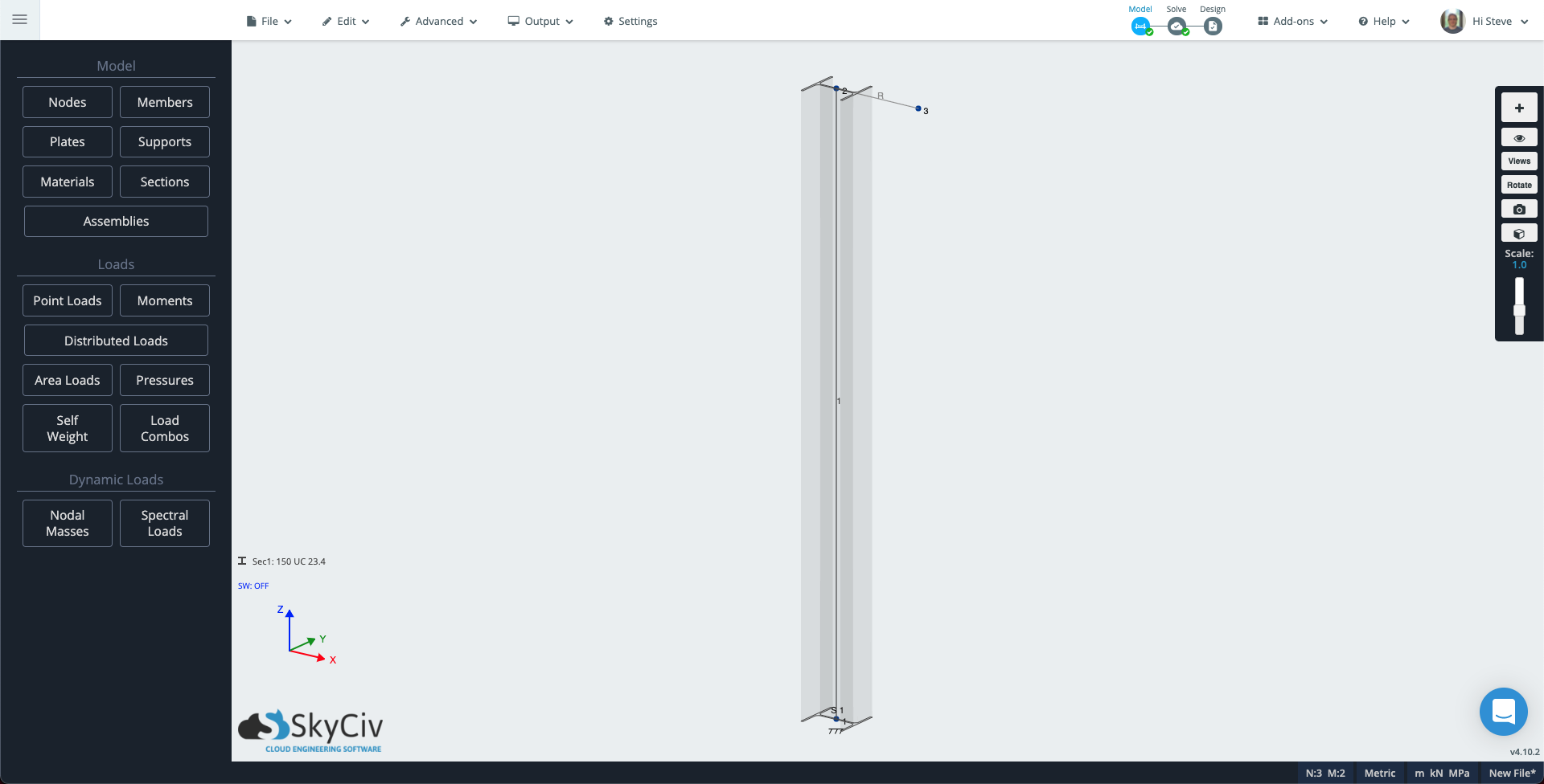
Su modelo debería verse similar al siguiente:
Haga clic en Cargas puntuales en el panel izquierdo. Complete los atributos con los siguientes valores:
- ID de nodo: 3
- De Magnitud: -5 (Si su modelo usa el eje Y como vertical, agregue este valor a la magnitud Y en su lugar).
- Grupo de carga: Carga de pandeo
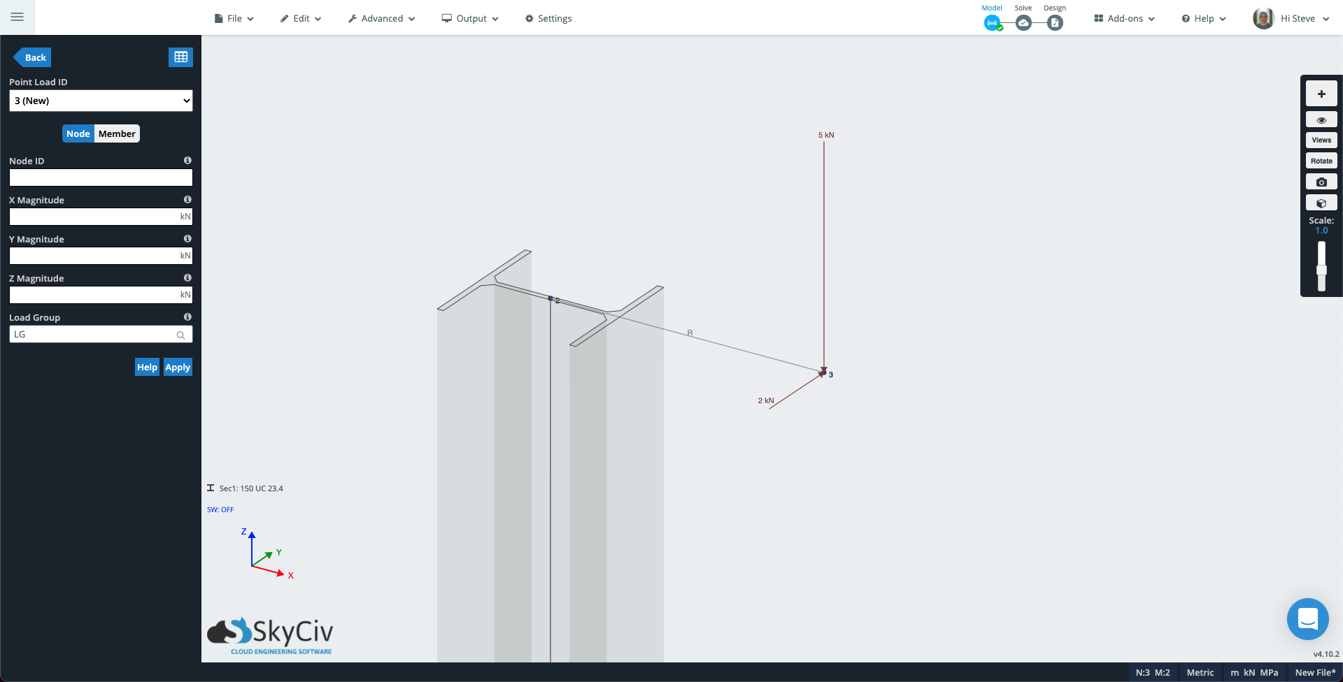
Haga clic en Aplicar y la carga puntual se agregará al modelo.. El ID de carga puntual aumentará a 2 (Nuevo) entonces agregue otra carga para crear torsión en la columna:
- ID de nodo: 3
- Y Magnitude: 2 (Si su modelo usa el eje Y como vertical, agregue este valor a la magnitud Z en su lugar).
- Grupo de carga: Carga de torsión
Nodo 3 de su modelo ahora debería tener un aspecto similar al siguiente.
Ejecute el solucionador, luego abra el modo de renderizado – el icono del cubo en el panel derecho. Cambie el menú desplegable en el panel izquierdo a Carga de pandeo, la escala de deflexión a Auto, y el menú desplegable Resultados de miembros para Suma de desplazamiento. Ahora puedes ver cómo la primera carga excéntrica está provocando un efecto de pandeo..
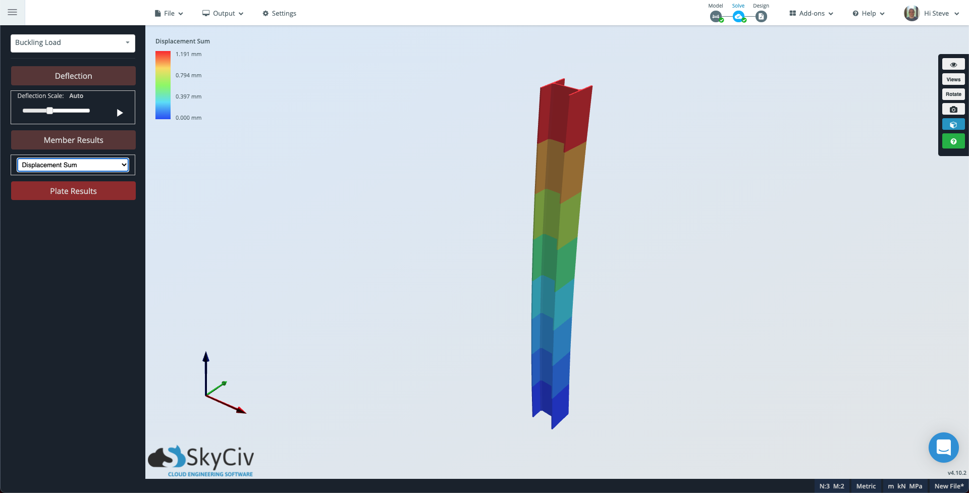
Tenga en cuenta que si desea ver una subdivisión más detallada del miembro, puede ir a Configuraciones Al arrastrar de izquierda a derecha, se seleccionará todo lo que toque el cuadro de selección. Solucionador, cambiar el Puntos de evaluación por miembro a un número adecuado y ejecute resolver nuevamente.
Ahora cambie el menú desplegable de Carga de pandeo a Carga de torsión y el Resultados de miembros a Tensión de torsión. En este caso, El miembro aparecerá gris ya que la carga de torsión es consistente en todo el miembro..
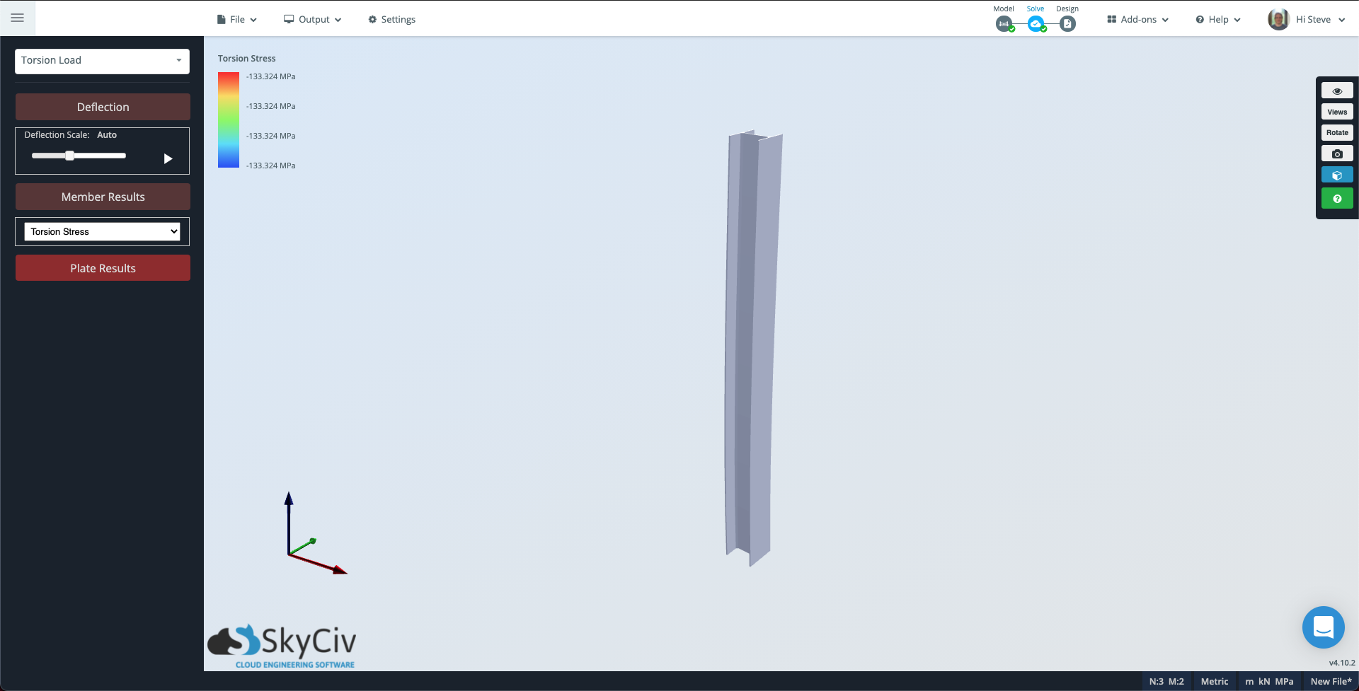
Observe que la escala del contorno en la parte superior izquierda todavía muestra la magnitud de la torsión que está experimentando la columna..