
Knee brace connection design to AISC 360 cubre dos articulaciones. At the brace end, Verifique que los pernos entre la riostra y la placa de refuerzo se deslicen., cojinete y desgarro, luego bloquear la ruptura por corte y tensión de ambas partes, y tensión y pandeo del cartela en su sección Whitmore. en la columna, you resolve the brace force at the column face, then check the gusset-to-column fillet welds, el refuerzo en corte y tensión a lo largo de ese borde, and the column web under the concentrated force.
Esta página funciona con un ejemplo real de principio a fin.. An L4x4x1/2 knee brace at 45° carries 100 saltar en tensión y 100 salto en compresión (LRFD). It is bolted with four 1 en pernos A490-SC a un 1/2 en grado A572 50 placa de refuerzo, which is welded to the flange of a W14x90 column with 3/16 en filetes por ambos lados. El diseño es para AISC. 360-16 y el Manual AISC 15ª edición. Cada ecuación está escrita con sus números., en el mismo orden que la hoja de cálculo AISC que el SkyCiv Connection Design El módulo produce para esta conexión..
What is a knee brace connection?
A knee brace is a short diagonal member that runs from a column to a beam or rafter a little way from the joint between them. It stiffens the corner of a frame and shortens the unbraced length of the members it ties together. Each end of the brace needs a connection, and this example designs the column end: the brace is bolted to a gusset plate, and the gusset is shop welded to the column flange.
The gusset is attached to the column along one edge only, which sets it apart from the corner gusset at a beam-column joint in a concentrically braced frame. Puedes comprobar este ejemplo directamente en el calculadora de conexión de rodillera. The same gusset checks appear in the calculadora de conexión de arriostramiento vertical y el calculadora de conexión de tirantes chevron.
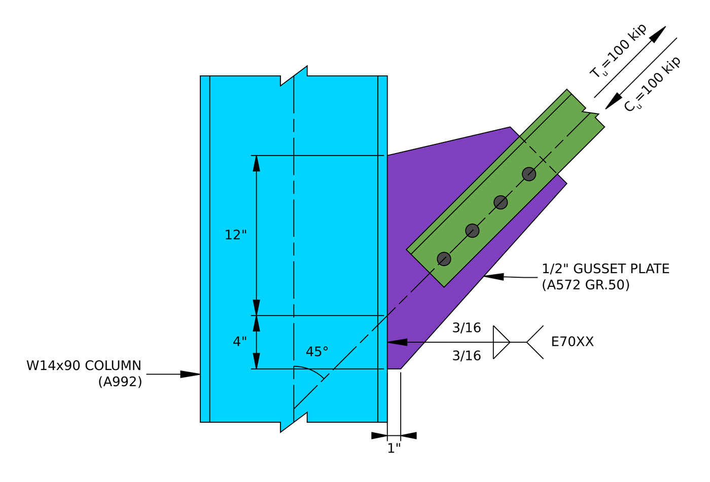
Elevación de la conexión de ejemplo.. The gusset weld runs 12 in above and 4 in below the point where the brace line crosses the column face.
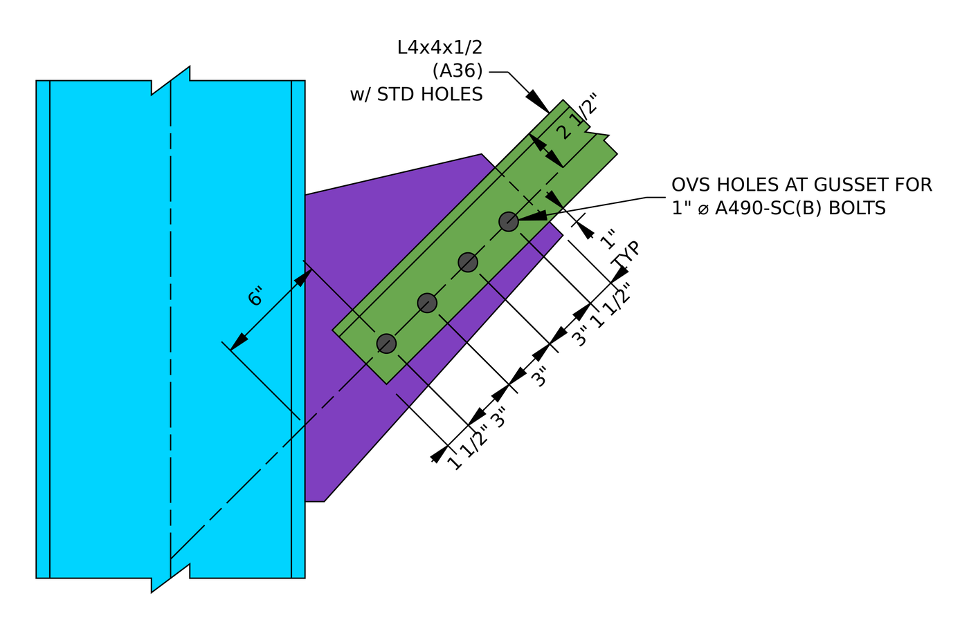
The brace connection. Four bolts at 3 en un 2 1/2 en calibre, con 1 1/2 in end distances on the angle and on the gusset.
Knee brace connection design: los pasos de un vistazo
- Verifique los límites de detalle en los pernos de refuerzo.: calibrar, espaciado y distancias al borde.
- Compruebe la resistencia al deslizamiento de los pernos de deslizamiento crítico..
- Compruebe el cojinete del perno y el desgarro de la placa de refuerzo..
- Compruebe el cojinete del perno y el desgarro de la abrazadera..
- Comprobar el corte del bloque de la cartela.
- Comprobar el corte del bloque de la riostra.
- Verifique la cartela en tensión en su sección Whitmore.
- Compruebe la rotura de la riostra en tensión con retraso de corte.
- Verifique la cartela en pandeo por compresión..
- Check the minimum fillet weld size at the column.
- Resolve the brace force at the column face and check the gusset-to-column weld.
- Check the gusset plate in shear yielding along the column.
- Check the gusset plate in tension yielding along the column.
- Check the column web for local crippling and local yielding.
Entradas de diseño para este ejemplo
El código de diseño es AISC. 360-16 LRFD. Las propiedades de la sección son del Manual AISC..
| Artículo | Símbolo | Valor |
|---|---|---|
| Carga de tensión de la riostra | [mathin] T_{u,br} [mathin] | 100 kip |
| Carga de compresión de la riostra | [mathin] C_{u,br} [mathin] | 100 kip |
| Columna | W14x90, A992 | |
| Profundidad de la columna / espesor de la red | [mathin] d_{c},\ t_{w,c} [mathin] | 14 in / 0.44 in |
| Ancho del ala de la columna / grosor | [mathin] b_{f,c},\ t_{f,c} [mathin] | 14.5 in / 0.71 in |
| Área de columna / dónde | [mathin] A_{c},\ k_{des,c} [mathin] | 26.5 pulgadas² / 1.31 in |
| Rendimiento de la columna / tensión de tracción | [mathin] F_{y,c},\ F_{u,c} [mathin] | 50 KSI / 65 KSI |
| Abrazadera | L4x4x1/2, A36 | |
| zona de refuerzo | [mathin] A_{br} [mathin] | 3.75 pulgadas² |
| Brace leg on / off gusset | [mathin] L_{on,gp,br},\ L_{off,gp,br} [mathin] | 4 in / 4 in |
| Brace thickness / centroide | [mathin] t_{br},\ \bar{y} [mathin] | 0.5 in / 1.18 in |
| Brace slope from support | [mathin] \theta_{br} [mathin] | 45° |
| Longitud sin arriostrar (longitud de pandeo del refuerzo) | [mathin] L_{b,br} [mathin] | 6 in |
| Rendimiento de refuerzo / tensión de tracción | [mathin] F_{y,br},\ F_{u,br} [mathin] | 36 KSI / 58 KSI |
| Módulo de elasticidad | [mathin] E [mathin] | 29000 KSI |
| Artículo | Símbolo | Valor |
|---|---|---|
| Cartela | 1/2 in, Grado A572 50 | |
| Espesor del refuerzo | [mathin] t_{gp} [mathin] | 0.5 in |
| Rendimiento de refuerzo / tensión de tracción | [mathin] F_{y,gp},\ F_{u,gp} [mathin] | 50 KSI / 65 KSI |
| Pernos | 1 en A490-SC, Superficie clase B | |
| Diámetro del perno | [mathin] d_{b} [mathin] | 1 in |
| Agujeros en el aparato ortopédico / escudete | Estándar (ETS) / de gran tamaño (OVS) | |
| Bolt gage on the brace leg | [mathin] g_{a} [mathin] | 2.5 in |
| Filas de pernos / espaciado entre filas | [mathin] n_{r},\ s_{r} [mathin] | 4 / 3 in |
| Columnas de pernos | [mathin] n_{c} [mathin] | 1 |
| Distancia final en refuerzo y cartela | [mathin] L_{ev} [mathin] | 1.5 in |
| Weld at the column | 3/16 en filete, ambos lados del refuerzo, E70XX | |
| Tamaño de soldadura / fuerza de relleno | [mathin] W,\ F_{EXX} [mathin] | 0.1875 in / 70 KSI |
| Weld length above / below the brace line | [mathin] L_{w1},\ L_{w2} [mathin] | 12 in / 4 in |
| Total gusset length along the column | [mathin] L_{WT} [mathin] | 16 in |
La longitud de la riostra en el refuerzo se suma a la del dibujo.: dos 1.5 in end distances plus three 3 en espacios, 12 in. The horizontal edge distance on the angle is the leg less the gage, 4 - 2.5 = 1.5 in.
Paso 1: Detallando límites en los pernos de riostra (AISC 360-16 J3.3, J3.4, J3.5)
La disposición de los pernos debe ser edificable y coincidir con los supuestos detrás de las ecuaciones de resistencia.. Los pernos que están demasiado cerca se rompen entre los agujeros., Los bordes que están demasiado cerca se arrancan., and the gage has to leave room to fit and tighten the bolts next to the angle’s outstanding leg.
Para 1 en perno el espacio mínimo es [mathin] 2\tfrac{2}{3} d_{b} = 2.667\,in [mathin] (J3.3) y la distancia mínima al borde es 1.25 in (Tabla J3.4). The angle has standard holes, asi que 1.25 se aplica directamente a él. El refuerzo tiene agujeros de gran tamaño., por lo que el incremento de la Tabla J3.5 de 1/8 in aumenta su distancia final mínima a 1.375 in.
| Límite de detalles | Límite (in) | Actual (in) | DCR | Resultado |
|---|---|---|---|---|
| Calibre mínimo de pernos | 1.875 | 2.500 | 0.750 | PASAR |
| Distancia mínima entre filas de tornillos | 2.667 | 3.000 | 0.889 | PASAR |
| Distancia máxima entre filas de tornillos | 6.000 | 3.000 | 0.500 | PASAR |
| Distancia mínima al borde vertical de la cartela | 1.375 | 1.500 | 0.917 | PASAR |
| Distancia mínima al borde vertical del arriostramiento | 1.250 | 1.500 | 0.833 | PASAR |
| Distancia mínima al borde horizontal del arriostramiento | 1.250 | 1.500 | 0.833 | PASAR |
Para un límite mínimo, la relación es límite sobre real, y para un máximo es un límite real por encima. La fila gobernante es la distancia del extremo del refuerzo con su incremento de orificio sobredimensionado.:
[math] DCR = \frac{d}{c} = \frac{(1.375)}{(1.5)} = 0.91667 [math]
DCR = 0.917 < 1.0, OK
Paso 2: Resistencia al deslizamiento de los pernos. (AISC 360-16 J3.8)
El refuerzo tiene agujeros de gran tamaño., y AISC 360-16 J3.2 permite agujeros de gran tamaño sólo en juntas de deslizamiento crítico. So the bolts are pretensioned and the brace force is carried by friction between the angle and the gusset. La comprobación es que la junta no resbale bajo la carga mayorada..
Dónde [mathin] \phi = 0.85 [mathin] para agujeros de gran tamaño, [mathin] \mu = 0.5 [mathin] para una superficie Clase B, [mathin] D_{u} = 1.13 [mathin], [mathin] h_{f} = 1 [mathin] porque no hay rellenos, [mathin] T_{b} = 64\,kip [mathin] para 1 en perno A490 (Tabla J3.1), [mathin] N_{s} = 1 [mathin] avión de deslizamiento, [mathin] n_{r} = 4 [mathin] y [mathin] n_{c} = 1 [mathin]:
[math] \phi R_{n} = \phi\, \mu\, D_{u}\, h_{f}\, T_{b}\, N_{s}\, n_{r}\, n_{c} [math]
[math] \phi R_{n} = (0.85) \times (0.5) \times (1.13) \times (1) \times (64\,kip) \times (1) \times (4) \times (1) [math]
[math] \phi R_{n} = 122.94\,kip [math]
DCR = 100 kip / 122.94 salto = 0.813 < 1.0, OK
El mismo control cubre tensión y compresión., porque la fuerza de arriostramiento es 100 dormir de cualquier manera.
Paso 3: Cojinete de perno y desgarro en la placa de refuerzo (AISC 360-16 J3.10)
Aún es necesario comprobar el rodamiento de los pernos críticos para el deslizamiento., porque si la junta se desliza los pernos terminan apoyando en los lados de sus agujeros. In tension the brace pulls the bolts away from the column, so they bear on the gusset toward its outer end. The bolt nearest that end has the least material in front of it.
El orificio del refuerzo es de gran tamaño., [mathin] d_{h} = 1.25\,in [mathin]. Distancia libre para el perno final, con [mathin] L_{ev} = 1.5\,in [mathin]:
[math] l_{c1} = L_{ev} – \frac{d_{h}}{2} = (1.5\,in) – \frac{(1.25\,in)}{2} = 0.875\,in [math]
Distancia libre entre pernos, con [mathin] s_{r} = 3\,in [mathin]:
[math] l_{c2} = s_{r} – d_{h} = (3\,in) – (1.25\,in) = 1.75\,in [math]
Dónde [mathin] t_{gp} = 0.5\,in [mathin], [mathin] F_{u,gp} = 65\,ksi [mathin], [mathin] n_{r} = 4 [mathin], [mathin] n_{c} = 1 [mathin], [mathin] d_{b} = 1\,in [mathin] y [mathin] \phi = 0.75 [mathin]:
[math] \phi R_{n,tearout} = \phi \left[ \min\left(1.2\, l_{c1},\, 2.4\, d_{b}\right) t_{gp} F_{u,gp}\, n_{c} + \min\left(1.2\, l_{c2},\, 2.4\, d_{b}\right) t_{gp} F_{u,gp}\, n_{c} \left( n_{r} – 1 \right) \right] [math]
[math] \phi R_{n,tearout} = (0.75) \times \left[ \min\left(1.2 \times (0.875\,in),\, 2.4 \times (1\,in)\right) \times (0.5\,in) \times (65\,ksi) \times (1) + \min\left(1.2 \times (1.75\,in),\, 2.4 \times (1\,in)\right) \times (0.5\,in) \times (65\,ksi) \times (1) \times ((4) – 1) \right] [math]
[math] \phi R_{n,tearout} = 179.16\,kip [math]
DCR = 100 kip / 179.16 salto = 0.558 < 1.0, OK
Tear-out governs every bolt here, because the large oversized hole eats into the clear distance: 1.2 lc está debajo 2.4 db for both the end bolt and the inner bolts. In compression the bolts bear toward the column instead, where there is far more gusset, Así que la tensión es el caso que importa..
Paso 4: Cojinete de perno y desgarro en la abrazadera. (AISC 360-16 J3.10)
The same check applies to the angle leg. In tension the angle is pulled away from the column, so its bolts bear toward the end of the angle nearest the column.
The angle has standard holes, [mathin] d_{h} = 1.125\,in [mathin]:
[math] l_{c1} = L_{ev} – \frac{d_{h}}{2} = (1.5\,in) – \frac{(1.125\,in)}{2} = 0.9375\,in [math]
[math] l_{c2} = s_{r} – d_{h} = (3\,in) – (1.125\,in) = 1.875\,in [math]
Dónde [mathin] t_{br} = 0.5\,in [mathin] y [mathin] F_{u,br} = 58\,ksi [mathin]:
[math] \phi R_{n,tearout} = \phi \left[ \min\left(1.2\, l_{c1},\, 2.4\, d_{b}\right) t_{br} F_{u,br}\, n_{c} + \min\left(1.2\, l_{c2},\, 2.4\, d_{b}\right) t_{br} F_{u,br}\, n_{c} \left( n_{r} – 1 \right) \right] [math]
[math] \phi R_{n,tearout} = (0.75) \times \left[ \min\left(1.2 \times (0.9375\,in),\, 2.4 \times (1\,in)\right) \times (0.5\,in) \times (58\,ksi) \times (1) + \min\left(1.2 \times (1.875\,in),\, 2.4 \times (1\,in)\right) \times (0.5\,in) \times (58\,ksi) \times (1) \times ((4) – 1) \right] [math]
[math] \phi R_{n,tearout} = 171.28\,kip [math]
DCR = 100 kip / 171.28 salto = 0.584 < 1.0, OK
The angle has the smaller hole but the weaker steel. A36 at 58 ksi against the gusset’s 65 ksi more than cancels the extra clear distance, so the brace ends up slightly weaker in bearing.
Paso 5: Corte en bloque de la cartela (AISC 360-16 J4.3)
A block of the gusset can tear out along the bolt line: shear along the line of bolts to the gusset’s end, plus tension across from the bolt line to the gusset’s side edge. With one line of bolts, the block is L-shaped.
Área neta en tensión, con [mathin] n_{c} = 1 [mathin], [mathin] s_{c} = 0\,in [mathin] and the gusset edge distance from the bolt line [mathin] L_{eh,gp} = 1.5\,in [mathin]. Cada agujero suma 1/16 en busca de daños durante el punzonado (B4.3):
[math] A_{nt} = t_{gp} \left[ (n_{c}-1)\, s_{c} + L_{eh,gp} – (n_{c} – 0.5) \left( d_{h} + 0.0625\,in \right) \right] [math]
[math] A_{nt} = (0.5\,in) \times \left[ ((1)-1) \times (0\,in) + (1.5\,in) – ((1) – 0.5) \times ((1.25\,in) + (0.0625\,in)) \right] = 0.42188\,in^{2} [math]
Área bruta en corte, from the gusset’s end to the farthest bolt:
[math] A_{gv} = t_{gp} \left[ L_{ev} + (n_{r}-1)\, s_{r} \right] = (0.5\,in) \times \left[ (1.5\,in) + ((4)-1) \times (3\,in) \right] = 5.25\,in^{2} [math]
Área neta en corte. El informe escribe la longitud de corte como la 12 en longitud de tirante en el refuerzo, [mathin] L_{br,gp} [mathin], menos distancia de un extremo, que es lo mismo 10.5 en como en el área bruta:
[math] A_{nv} = t_{gp} \left[ L_{br,gp} – L_{ev} – (n_{r} – 0.5)\left( d_{h} + 0.0625\,in \right) \right] [math]
[math] A_{nv} = (0.5\,in) \times \left[ (12\,in) – (1.5\,in) – ((4) – 0.5) \times ((1.25\,in) + (0.0625\,in)) \right] = 2.9531\,in^{2} [math]
Resistencia al corte del bloque, con [mathin] U_{bs} = 1 [mathin] porque el esfuerzo de tensión es uniforme, [mathin] F_{u,gp} = 65\,ksi [mathin], [mathin] F_{y,gp} = 50\,ksi [mathin] y [mathin] \phi = 0.75 [mathin]:
[math] \phi R_{n} = \phi \left( 0.6\, F_{u,gp} A_{nv} + U_{bs} F_{u,gp} A_{nt} \le 0.6\, F_{y,gp} A_{gv} + U_{bs} F_{u,gp} A_{nt} \right) [math]
[math] \phi R_{n} = (0.75) \times \left( 0.6 \times (65\,ksi) \times (2.9531\,in^{2}) + (1) \times (65\,ksi) \times (0.42188\,in^{2}) \le 0.6 \times (50\,ksi) \times (5.25\,in^{2}) + (1) \times (65\,ksi) \times (0.42188\,in^{2}) \right) [math]
[math] \phi R_{n} = 106.95\,kip [math]
DCR = 100 kip / 106.95 salto = 0.935 < 1.0, OK
Shear rupture on the net section governs. El 1 1/4 en agujeros de gran tamaño tomar 4.59 dentro fuera del 10.5 en longitud de corte, which is why this check runs so close.
Paso 6: Corte en bloque de la riostra (AISC 360-16 J4.3)
The angle leg can tear out the same way: shear along the bolt line to the end of the angle, plus tension from the bolt line to the toe of the leg.
The horizontal edge distance on the angle is [mathin] L_{eh,br} = 1.5\,in [mathin] and the hole is [mathin] d_{h} = 1.125\,in [mathin]:
[math] A_{nt} = t_{br} \left[ (n_{c}-1)\, s_{c} + L_{eh,br} – (n_{c} – 0.5) \left( d_{h} + 0.0625\,in \right) \right] [math]
[math] A_{nt} = (0.5\,in) \times \left[ ((1)-1) \times (0\,in) + (1.5\,in) – ((1) – 0.5) \times ((1.125\,in) + (0.0625\,in)) \right] = 0.45313\,in^{2} [math]
[math] A_{gv} = t_{br} \left[ L_{ev} + (n_{r}-1)\, s_{r} \right] = (0.5\,in) \times \left[ (1.5\,in) + ((4)-1) \times (3\,in) \right] = 5.25\,in^{2} [math]
[math] A_{nv} = t_{br} \left[ L_{br,gp} – L_{ev} – (n_{r} – 0.5)\left( d_{h} + 0.0625\,in \right) \right] [math]
[math] A_{nv} = (0.5\,in) \times \left[ (12\,in) – (1.5\,in) – ((4) – 0.5) \times ((1.125\,in) + (0.0625\,in)) \right] = 3.1719\,in^{2} [math]
Con [mathin] F_{u,br} = 58\,ksi [mathin], [mathin] F_{y,br} = 36\,ksi [mathin], [mathin] U_{bs} = 1 [mathin] y [mathin] \phi = 0.75 [mathin]:
[math] \phi R_{n} = \phi \left( 0.6\, F_{u,br} A_{nv} + U_{bs} F_{u,br} A_{nt} \le 0.6\, F_{y,br} A_{gv} + U_{bs} F_{u,br} A_{nt} \right) [math]
[math] \phi R_{n} = (0.75) \times \left( 0.6 \times (58\,ksi) \times (3.1719\,in^{2}) + (1) \times (58\,ksi) \times (0.45313\,in^{2}) \le 0.6 \times (36\,ksi) \times (5.25\,in^{2}) + (1) \times (58\,ksi) \times (0.45313\,in^{2}) \right) [math]
[math] \phi R_{n} = 102.5\,kip [math]
DCR = 100 kip / 102.5 salto = 0.976 < 1.0, OK
Esta es la verificación que rige toda la conexión.. Net shear rupture governs again, though only just: the yield side of the equation is within 3 kip of it.
Paso 7: Cartela en tensión en la sección Whitmore (AISC 360-16 J4.1)
La fuerza del arriostramiento ingresa al refuerzo a través de los pernos y se propaga a medida que viaja a lo largo de la placa.. The Whitmore section is the effective width that takes that force at the last bolt: lines drawn from the first bolt, spreading out on each side, measured across the last bolt (Parte del manual AISC 9, Fig. 9-1). El refuerzo no debe ceder en ese ancho., and it must not rupture on that width less the hole.
Ancho de Whitmore
El grupo de tornillos es [mathin] L_{br} = (n_{r}-1)\, s_{r} = 9\,in [mathin] long and has a single bolt line, asi que [mathin] W_{br} = 0\,in [mathin]. en el informe, [mathin] W [mathin] en este paso es el ancho de Whitmore, no el tamaño de la soldadura:
[math] W = 2\, L_{br} \tan(\theta) + W_{br} = 2 \times (9\,in) \times \tan((18.93)) + (0\,in) = 6.1732\,in [math]
The Manual’s spread angle is 30°, which would give 2 × 9 × tan 30° = 10.39 in. But the gusset’s sloping free edge on the toe side of the angle passes only about 3.1 in from the last bolt, so a 30° line would run off the plate. The report cuts the spread back to 18.93°, which puts the edge of the Whitmore section 3.0866 in from the bolt line, at that free edge, and uses the same width on the other side. Only steel that is actually there is counted.
Cediendo la tensión (Eq. J4-1)
Con [mathin] \phi = 0.9 [mathin], [mathin] F_{y,gp} = 50\,ksi [mathin] y [mathin] t_{gp} = 0.5\,in [mathin]:
[math] \phi R_{n,ty} = \phi\, F_{y,gp}\, t_{gp}\, W = (0.9) \times (50\,ksi) \times (0.5\,in) \times (6.1732\,in) = 138.9\,kip [math]
ruptura de tensión (Eq. J4-2)
The net width removes one oversized hole, [mathin] d_{h} = 1.25\,in [mathin], con [mathin] \phi = 0.75 [mathin] y [mathin] F_{u,gp} = 65\,ksi [mathin]:
[math] \phi R_{n,tr} = \phi\, F_{u,gp}\, t_{gp} \left[ W – n_{c}\left( d_{h} + 0.0625\,in \right) \right] [math]
[math] \phi R_{n,tr} = (0.75) \times (65\,ksi) \times (0.5\,in) \times \left[ (6.1732\,in) – (1) \times ((1.25\,in) + (0.0625\,in)) \right] = 118.48\,kip [math]
[math] \phi R_{n} = \min\left( \phi R_{n,ty},\, \phi R_{n,tr} \right) = \min\left( (138.9\,kip),\, (118.48\,kip) \right) = 118.48\,kip [math]
DCR = 100 kip / 118.48 salto = 0.844 < 1.0, OK
Paso 8: Arriostramiento en rotura por tensión con retraso de corte (AISC 360-16 D3, J4.1)
Only one leg of the angle is bolted, so the force has to flow from the outstanding leg into the bolted leg near the connection. Esa tensión desigual es el retraso de corte, y AISC lo maneja con el factor U, lo que reduce el área neta.
De la Tabla D3.1, Caso 2, with the angle’s centroid [mathin] \bar{y} = 1.18\,in [mathin] measured from the bolted face and the connection length [mathin] (n_{r} – 1)\, s_{r} = 9\,in [mathin]:
[math] U = 1 – \frac{\bar{y}}{(n_{r} – 1)\, s_{r}} = 1 – \frac{(1.18\,in)}{((4) – 1) \times (3\,in)} = 0.86894 [math]
Dónde [mathin] A_{br} = 3.75\,in^{2} [mathin], [mathin] d_{h} = 1.125\,in [mathin], [mathin] t_{br} = 0.5\,in [mathin], [mathin] F_{u,br} = 58\,ksi [mathin] y [mathin] \phi = 0.75 [mathin]:
[math] \phi R_{n,tr} = \phi\, F_{u,br}\, U \left[ A_{br} – n_{c}\left( d_{h} + 0.0625\,in \right) t_{br} \right] [math]
[math] \phi R_{n,tr} = (0.75) \times (58\,ksi) \times (0.86894) \times \left[ (3.75\,in^{2}) – (1) \times ((1.125\,in) + (0.0625\,in)) \times (0.5\,in) \right] = 119.3\,kip [math]
DCR = 100 kip / 119.3 salto = 0.838 < 1.0, OK
A longer bolt group raises U. With six bolts instead of four, the connection length would be 15 in and U would be 1 - 1.18/15 = 0.92.
Paso 9: Cartela en pandeo por compresión (AISC 360-16 J4.4, E3)
When the brace is in compression it pushes the gusset toward the column. The strip of gusset between the last bolt and the column face can buckle out of plane, por lo que se verifica como una columna con el ancho de Whitmore como sección transversal.
La longitud de pandeo es la 6 como se muestra en el dibujo, from the line of the bolt nearest the column to the column face, medido a lo largo de la abrazadera. El informe lo etiqueta como longitud de llave sin llave., [mathin] L_{b,br} = 6\,in [mathin]. The gusset is welded to the column on one edge only and its free end can sway out of plane with the brace, entonces el informe toma [mathin] K = 1.2 [mathin]. Para un rectángulo sólido, [mathin] r = t_{gp}/\sqrt{12} = 0.14434\,in [mathin]:
[math] \frac{KL}{r} = \frac{(1.2) \times (6\,in)}{(0.5\,in)/\sqrt{12}} = 49.883 [math]
Ya que [mathin] KL/r \gt 25 [mathin], J4.4 envía el cheque al Capítulo E. Tensión de pandeo elástico:
[math] F_{e} = \frac{\pi^{2} E}{\left( \frac{KL}{r} \right)^{2}} = \frac{\pi^{2} \times (29000\,ksi)}{((49.883))^{2}} = 115.02\,ksi [math]
[math] 4.71 \sqrt{\frac{E}{F_{y}}} = 113.43 [math]
Ya que [mathin] KL/r \le 4.71\sqrt{E/F_{y}} [mathin], se aplica la ecuación inelástica E3-2:
[math] F_{cr} = \left( 0.658^{\frac{F_{y,gp}}{F_{e}}} \right) F_{y,gp} = \left( 0.658^{\frac{(50\,ksi)}{(115.02\,ksi)}} \right) \times (50\,ksi) = 41.683\,ksi [math]
Con [mathin] \phi = 0.9 [mathin] y el ancho de Whitmore [mathin] W = 6.1732\,in [mathin]:
[math] \phi R_{n} = \phi\, F_{cr}\, t_{gp}\, W = (0.9) \times (41.683\,ksi) \times (0.5\,in) \times (6.1732\,in) = 115.79\,kip [math]
DCR = 100 kip / 115.79 salto = 0.864 < 1.0, OK
The Whitmore width drives this check as much as the slenderness. A gusset with more plate below the brace would get a wider section and a higher strength.
Paso 10: Minimum fillet weld size at the column (AISC 360-16 J2.2b)
Una soldadura de filete que es demasiado pequeña para las piezas que une puede agrietarse al enfriarse., porque la parte más gruesa extrae el calor demasiado rápido. La tabla J2.4 establece el mínimo por parte más delgada unida. Aquí ese es el 1/2 en refuerzo, que cae por encima 1/4 dentro 1/2 en banda, entonces el mínimo es 3/16 in.
| Límite de detalles | Límite (in) | Actual (in) | DCR | Resultado |
|---|---|---|---|---|
| Tamaño mínimo de soldadura de filete | 0.188 | 0.188 | 1.000 | PASAR |
[math] DCR = \frac{d}{c} = \frac{(0.188)}{(0.188)} = 1 [math]
DCR = 1.000, OK
una proporción de 1.000 here is not a near miss. It only says the 3/16 en soldadura es exactamente el tamaño más pequeño permitido, which is a common and sensible choice.
Paso 11: Gusset-to-column weld (AISC 360-16 J2.4, Guía de diseño AISC 29)
The gusset is welded to the column flange with a 3/16 en filete de cada lado. The brace force reaches the column face at an angle and off the centre of the weld, so the weld carries a normal force, a shear and a moment together. This step resolves the brace force at the column face, encuentra la peor carga en la soldadura, y comprueba la soldadura contra ella..
Límite del metal base en el tamaño de la soldadura (Ecuación manual AISC. 9-2)
El refuerzo tiene una soldadura en ambas caras., por lo que la mitad de su espesor respalda cada soldadura. Con [mathin] t_{f,c} = 0.71\,in [mathin], [mathin] F_{u,c} = 65\,ksi [mathin], [mathin] t_{gp} = 0.5\,in [mathin] y [mathin] F_{u,gp} = 65\,ksi [mathin]:
[math] D_{max} = \frac{t_{f,c} F_{u,c} \le \frac{t_{gp}}{2} F_{u,gp}}{3.09\,kip/in \times F_{EXX}/F_{E70XX}} = \frac{(0.71\,in) \times (65\,ksi) \le (0.25\,in) \times (65\,ksi)}{(3.09\,kip/in) \times (1)} = 5.2589 [math]
Eso es 5.2589 dieciseisavos, respecto 0.329 in, entonces el completo 3/16 en recuentos de soldadura.
Longitud efectiva de soldadura
El refuerzo corre [mathin] L_{WT} = 16\,in [mathin] along the column. Cada una de las dos líneas de soldadura se reduce en 2W para los extremos.:
[math] L_{w} = 2 \left[ L_{WT} – 2W \right] = 2 \times \left[ (16\,in) – 2 \times (0.1875\,in) \right] = 31.25\,in [math]
Forces at the column face
Split the 100 kip brace force, [mathin] P_{u,br} [mathin], into a component perpendicular to the column face and one along it:
[math] N_{br} = P_{u,br} \sin(\theta_{br}) = (100\,kip) \times \sin((45)) = 70.711\,kip [math]
[math] V_{br} = P_{u,br} \cos(\theta_{br}) = (100\,kip) \times \cos((45)) = 70.711\,kip [math]
The brace line crosses the column face 12 in below the top of the gusset and 4 in above its bottom, so it misses the middle of the 16 in weld by [mathin] (12 – 4)/2 = 4\,in [mathin]. The shear acts along the weld line and makes no moment about it, but the normal force is 4 in off centre:
[math] M_{br} = \frac{N_{br} \left| L_{w1} – L_{w2} \right|}{2} = \frac{(70.711\,kip) \times |(12\,in) – (4\,in)|}{2} = 23.57\,kip{\cdot}ft [math]
Eso es 282.84 pollo en. El momento se suma a la fuerza normal en un extremo de la soldadura y se resta en el otro.. El informe convierte el momento en una fuerza normal equivalente utilizando el módulo de sección plástica de las dos líneas de soldadura., [mathin] L_{w}^{2}/8 [mathin], lo que da la carga normal máxima:
[math] N_{br,T} = \frac{8\, M_{br}}{L_{w}} + N_{br} = \frac{8 \times (23.57\,kip{\cdot}ft)}{(31.25\,in)} + (70.711\,kip) = 143.12\,kip [math]
El momento se convierte en kip-in. (× 12) dentro de esa fracción. La resultante en el pico y su ángulo con el eje de soldadura.:
[math] R = \sqrt{\left( N_{br,T} \right)^{2} + \left( V_{br} \right)^{2}} = \sqrt{((143.12\,kip))^{2} + ((70.711\,kip))^{2}} = 159.63\,kip [math]
[math] \theta = \tan^{-1}\left| \frac{N_{br,T}}{V_{br}} \right| = \tan^{-1}\left| \frac{(143.12\,kip)}{(70.711\,kip)} \right| = 63.707 [math]
Factor de ductilidad de soldadura
La carga sobre la soldadura no es uniforme.. Llega a su punto máximo en un extremo y cae casi a la nada en el otro.. Las soldaduras de filete tienen ductilidad limitada., entonces guía de diseño AISC 29 y parte del manual AISC 13 diseñar una soldadura de borde de refuerzo para la mayor carga máxima y 1.25 veces el promedio de las cargas máxima y mínima. El 1.25 Permite que la soldadura redistribuya la carga antes de que se fracture..
En el extremo de baja tensión, la flexión se resta de la fuerza normal.:
[math] N_{br,min} = \left| N_{br} – \frac{8\, M_{br}}{L_{w}} \right| = \left| (70.711\,kip) – \frac{8 \times (23.57\,kip{\cdot}ft)}{(31.25\,in)} \right| = 1.6971\,kip [math]
[math] R_{min} = \sqrt{\left( N_{br,min} \right)^{2} + \left( V_{br} \right)^{2}} = \sqrt{((1.6971\,kip))^{2} + ((70.711\,kip))^{2}} = 70.731\,kip [math]
[math] R_{w} = \max\left( R,\, 1.25\, \frac{R + R_{min}}{2} \right) = \max\left( (159.63\,kip),\, 1.25 \times \frac{(159.63\,kip) + (70.731\,kip)}{2} \right) = 159.63\,kip [math]
El valor promedio es 143.98 kip, entonces el pico gobierna.
Fuerza de soldadura (Eq. J2-4)
The resultant is at 63.707° to the weld, entonces el factor direccional [mathin] 1 + 0.5 \sin^{1.5}\theta [mathin] agrega sobre 42% a la fuerza. Con [mathin] \phi = 0.75 [mathin] y [mathin] F_{EXX} = 70\,ksi [mathin]:
[math] \phi R_{n} = \phi\, 0.6\, F_{EXX} \frac{\sqrt{2}}{2} \left( W \le \frac{D_{max}}{16} \right) \left[ 1 + 0.5 \left( \sin\theta \right)^{1.5} \right] L_{w} [math]
[math] \phi R_{n} = (0.75) \times 0.6 \times (70\,ksi) \times \frac{\sqrt{2}}{2} \times \left( (0.1875\,in) \le \frac{(5.2589)}{(16)} \right) \times \left[ 1 + 0.5 \times (\sin(63.707))^{1.5} \right] \times (31.25\,in) [math]
[math] \phi R_{n} = 185.91\,kip [math]
DCR = 159.63 kip / 185.91 salto = 0.859 < 1.0, OK
El 4 in eccentricity costs a lot here. Without it the weld would carry a 100 kip resultant instead of 159.63 kip. Centring the gusset on the point where the brace line crosses the column face removes the moment.
Paso 12: Gusset plate in shear yielding along the column (AISC 360-16 J4.2)
The component of the brace force along the column face, [mathin] V_{br} = 70.711\,kip [mathin], pasa a través del borde soldado del refuerzo como corte. La sección bruta a lo largo de ese borde no debe ceder.
Con [mathin] L_{WT} = 16\,in [mathin], [mathin] t_{gp} = 0.5\,in [mathin], [mathin] F_{y,gp} = 50\,ksi [mathin] y [mathin] \phi = 1 [mathin]:
[math] A_{gv} = L_{WT}\, t_{gp} = (16\,in) \times (0.5\,in) = 8\,in^{2} [math]
[math] \phi R_{n,sy} = \phi\, 0.6\, F_{y,gp} A_{gv} = (1) \times 0.6 \times (50\,ksi) \times (8\,in^{2}) = 240\,kip [math]
DCR = 70.711 kip / 240 salto = 0.295 < 1.0, OK
Paso 13: Gusset plate in tension yielding along the column (AISC 360-16 J4.1)
The normal component and the moment put the gusset’s welded edge in tension, más alto en un extremo. Siguiendo la guía de diseño AISC 29, Ejemplo 5.3, el informe suma las dos tensiones normales en el borde y convierte el pico nuevamente en una fuerza equivalente sobre todo el borde.
El estrés normal es [mathin] N/(t\,l) + M/(t\,l^{2}/4) [mathin]. Multiplicando por [mathin] t\,l [mathin], con [mathin] l = L_{WT} = 16\,in [mathin]:
[math] N_{e} = \left| N_{br} \right| + \frac{4 \left| M_{br} \right|}{L_{WT}} = |(70.711\,kip)| + \frac{4 \times |(23.57\,kip{\cdot}ft)|}{(16\,in)} = 141.42\,kip [math]
Esto está ligeramente por debajo del valor de la soldadura. 143.12 kip porque usa el 16 en el borde del refuerzo en lugar del 31.25 pulgadas de soldadura efectiva dividida en dos líneas. Con [mathin] \phi = 0.9 [mathin]:
[math] \phi R_{n,ty} = \phi\, F_{y,gp}\, t_{gp}\, L_{WT} = (0.9) \times (50\,ksi) \times (0.5\,in) \times (16\,in) = 360\,kip [math]
DCR = 141.42 kip / 360 salto = 0.393 < 1.0, OK
Paso 14: Column web local crippling and local yielding (AISC 360-16 J10.3, J10.2)
The gusset delivers a concentrated force to the column flange over its 16 de largo. When the brace is in compression, that force pushes on the flange, and the column web behind it can yield locally or crumple (lisiado). La demanda es la carga normal máxima del paso 11, [mathin] N_{br,T} = 143.12\,kip [mathin].
Web local paralizante (Eq. J10-4)
Con [mathin] \phi = 0.75 [mathin], [mathin] t_{w,c} = 0.44\,in [mathin], longitud del rodamiento [mathin] L_{WT} = 16\,in [mathin], [mathin] d_{c} = 14\,in [mathin], [mathin] t_{f,c} = 0.71\,in [mathin], [mathin] F_{y,c} = 50\,ksi [mathin] y [mathin] Q_{f} = 1 [mathin]:
[math] \phi R_{n,wlc} = \phi\, 0.8 \left( t_{w,c} \right)^{2} \left[ 1 + 3 \left( \frac{L_{WT}}{d_{c}} \right) \left( \frac{t_{w,c}}{t_{f,c}} \right)^{1.5} \right] \sqrt{\frac{E\, F_{y,c}\, t_{f,c}}{t_{w,c}}}\, Q_{f} [math]
[math] \phi R_{n,wlc} = (0.75) \times 0.8 \times ((0.44\,in))^{2} \times \left[ 1 + 3 \times \left( \frac{(16\,in)}{(14\,in)} \right) \times \left( \frac{(0.44\,in)}{(0.71\,in)} \right)^{1.5} \right] \times \sqrt{\frac{(29000\,ksi) \times (50\,ksi) \times (0.71\,in)}{(0.44\,in)}} \times (1) [math]
[math] \phi R_{n,wlc} = 474.88\,kip [math]
Rendimiento local web (Eq. J10-2)
La fuerza se propaga a través de la brida y el filete en una 2.5:1 pendiente a cada lado, entonces la web cede [mathin] 5k + l_{b} [mathin]. Con [mathin] \phi = 1 [mathin] y [mathin] k_{des,c} = 1.31\,in [mathin]:
[math] \phi R_{n,wly} = \phi\, F_{y,c}\, t_{w,c} \left( 5\, k_{des,c} + L_{WT} \right) = (1) \times (50\,ksi) \times (0.44\,in) \times \left( 5 \times (1.31\,in) + (16\,in) \right) = 496.1\,kip [math]
[math] \phi R_{n} = \min\left( \phi R_{n,wlc},\, \phi R_{n,wly} \right) = \min\left( (474.88\,kip),\, (496.1\,kip) \right) = 474.88\,kip [math]
DCR = 143.12 kip / 474.88 salto = 0.301 < 1.0, OK
A long gusset spreads the force well, so the column web has plenty in reserve and needs no stiffener.
Resumen de controles
| Verificación de diseño | Demanda | Capacidad | DCR | Resultado |
|---|---|---|---|---|
| Detallando límites en los pernos de riostra | 1.375 in | 1.500 in | 0.917 | PASAR |
| Pernos en corte (deslizamiento crítico) | 100.000 kip | 122.944 kip | 0.813 | PASAR |
| Soporte de perno en la cartela | 100.000 kip | 179.156 kip | 0.558 | PASAR |
| Rodamiento de perno en la abrazadera | 100.000 kip | 171.281 kip | 0.584 | PASAR |
| Corte en bloque de la cartela | 100.000 kip | 106.945 kip | 0.935 | PASAR |
| Corte en bloque de la riostra | 100.000 kip | 102.497 kip | 0.976 | PASAR |
| Placa de refuerzo en tensión | 100.000 kip | 118.480 kip | 0.844 | PASAR |
| Brazalete en ruptura de tensión | 100.000 kip | 119.303 kip | 0.838 | PASAR |
| Placa de refuerzo en compresión | 100.000 kip | 115.792 kip | 0.864 | PASAR |
| Tamaño mínimo de soldadura de filete | 0.188 in | 0.188 in | 1.000 | PASAR |
| Weld at gusset to column | 159.634 kip | 185.906 kip | 0.859 | PASAR |
| Gusset shear yielding along the column | 70.711 kip | 240.000 kip | 0.295 | PASAR |
| Gusset tension yielding along the column | 141.421 kip | 360.000 kip | 0.393 | PASAR |
| Column web (gobiernos locales paralizantes) | 143.118 kip | 474.882 kip | 0.301 | PASAR |
The connection passes every check of this knee brace connection design. Block shear of the brace governs the strength checks at 0.976, with block shear of the gusset next at 0.935. Both come from the same short bolt line with large holes. El tamaño mínimo de soldadura muestra 1.000 sólo porque la soldadura es exactamente el mínimo de la Tabla J2.4. en la columna, the weld is the busiest item at 0.859, mostly because of the 4 in eccentricity.
Qué cambiar si falla un cheque
- Block shear of the brace or gusset: agregar una fila de tornillos, lo que alarga los planos de corte. A larger end distance or a longer edge distance to the gusset’s side also helps. On the gusset, standard holes instead of oversized holes add net area.
- Resistencia al deslizamiento: agregar pernos, use un perno más grande, o utilice agujeros estándar en el refuerzo, que eleva φ de 0.85 a 1.00.
- Rodamiento y desgarro: aumentar la distancia final o el espacio entre pernos, o usar un refuerzo más grueso.
- Ruptura de la tensión del corsé: alargar el grupo de pernos para elevar U, or use a heavier angle.
- Tensión o compresión del refuerzo.: un refuerzo más grueso eleva ambos. Adding plate on the toe side of the brace widens the Whitmore section, and moving the bolts closer to the column shortens the buckling length.
- Weld at the column: centre the gusset on the point where the brace line meets the column face to remove the moment, make the gusset longer, or use a larger fillet. The base metal allows up to about 5/16 aquí.
- Column web: alargar el refuerzo para distribuir la fuerza, or add a pair of stiffeners or a doubler plate.
Preguntas frecuentes
What is a knee brace used for?
A knee brace is a short diagonal between a column and a beam or rafter, set a short distance from their joint. It stiffens the frame corner against sway and gives the members an intermediate brace point. Because it is short and sits close to the joint, it often carries a large axial force for its size, in tension or compression depending on which way the frame sways. That is why this example designs for 100 kip both ways.
¿Por qué los pernos tienen un deslizamiento crítico??
El refuerzo tiene agujeros de gran tamaño., which give the erector tolerance to fit the brace. AISC 360-16 J3.2 permite agujeros de gran tamaño sólo en conexiones de deslizamiento crítico, por lo que los pernos están pretensados y las superficies de unión están preparadas para Clase B. Un aparato ortopédico que invierte entre tensión y compresión también se beneficia de una articulación que no se desliza hacia adelante y hacia atrás.. Los pernos con deslizamiento crítico aún se revisan para comprobar si tienen rodamientos y desgarros., como en pasos 3 y 4.
¿Qué es la sección Whitmore?, and why is the spread angle 18.93° here?
La sección Whitmore es el ancho efectivo del refuerzo que resiste la fuerza del arriostramiento al final del grupo de pernos.. You find it by drawing lines at 30° from the first bolt on each side of the bolt line and measuring across them at the last bolt. In this example the gusset’s sloping free edge is closer to the bolts than those 30° lines would reach, so the report limits the spread to 18.93°. The Whitmore width then stays inside the plate, a 6.1732 en lugar de 10.39 in.
¿Por qué K = 1.2 utilizado para pandeo de cartelas?
The gusset is welded to the column along one edge, y el extremo de la riostra puede moverse libremente fuera del plano. Es una columna fijada contra la rotación en ambos extremos pero libre de trasladarse en uno., para lo cual el comentario del AISC recomienda una K de 1.2. Un refuerzo de esquina unido tanto a una viga como a una columna se sostiene en dos bordes y generalmente se le asigna una K más baja.. Utilizando 1.2 for a knee brace gusset is the conservative choice.
Where does the moment on the gusset-to-column weld come from?
The brace line meets the column face 12 in below the top of the gusset and 4 in above its bottom, so it misses the centre of the 16 in weld by 4 in. The normal component of the brace force, 70.711 kip, interino 4 in off centre gives a moment of 282.84 pollo en, o 23.57 kip-ft. If the gusset were centred on that crossing point there would be no moment, and the weld would only see the 100 kip brace force.
Why is the gusset weld designed for 1.25 times the average load?
The load along a gusset edge weld is uneven, and fillet welds cannot stretch far before they fracture. Guía de diseño AISC 29 designs the weld for the larger of the peak load and 1.25 veces el promedio de las cargas máxima y mínima, using the weld ductility factor from AISC Manual Part 13. That makes sure the weld can redistribute load along its length. In this example the peak load of 159.63 kip governs over the 143.98 kip average-based value.
Is the Uniform Force Method used for a knee brace gusset?
No. The Uniform Force Method distributes a brace force between the beam and column interfaces of a gusset attached to both, at a beam-column-brace work point. A knee brace gusset is attached to the column flange only. So the brace force is resolved at the column face as a normal force, a shear and a moment, and the gusset edge and its weld are checked for those three together.
¿Cómo cambiaría esto para AISC ASD en lugar de LRFD??
Los estados límite y las resistencias nominales son idénticos.. Con AISC ASD se compara la fuerza de refuerzo del nivel de servicio con la resistencia nominal dividida por un factor de seguridad en lugar de multiplicarla por un factor de resistencia.. un factor de resistencia de 0.75 se convierte en un factor de seguridad de 2.00, 0.90 se convierte 1.67, y el resbalón con agujeros de gran tamaño va desde 0.85 a 1.76. Las combinaciones de carga también cambian., entonces la demanda es menor.
Design a knee brace connection for free
Cada número en esta página proviene de una solución.. Pick the knee brace configuration, enter your column, abrazadera, escudete, tornillos, fuerzas de soldadura y refuerzo, y mira cada una de estas comprobaciones en tu navegador. No hay nada que instalar.
El módulo SkyCiv Connection Design es el software de diseño de conexiones detrás de este ejemplo.. Le brinda el informe de cálculo completo con cada ecuación y sus números en ella., como los pasos anteriores, más todas las capacidades y DCR, según AISC 360-16 (LRFD y TEA) y AS 4100:2020. El calculadora de pernos y calculadora de soldadura Cubra el grupo de tornillos y verifique las soldaduras por su cuenta..
Referencias
- AISC 360-16, Especificación para edificios de acero estructural: B4.3, D3 (Cuadro D3.1 Caso 2), E3 (Eq. E3-1, E3-2, E3-4), J2.2b (Tabla J2.4), J2.4 (Eq. J2-4), J3.2, J3.3, J3.4 (Tabla J3.4), J3.5 (Tabla J3.5), J3.8 (Eq. J3-4, Tabla J3.1), J3.10 (Eq. J3-6a, J3-6c), J4.1 (Eq. J4-1, J4-2), J4.2 (Eq. J4-3), J4.3 (Eq. J4-5), J4.4, J10.2 (Eq. J10-2), J10.3 (Eq. J10-4).
- Manual de construcción en acero AISC, 15a edición: Parte 9, Fig. 9-1 (Sección Whitmore, página de referencia 9-4) Determine la deflexión y el ángulo de rotación en el extremo B de la viga mostrada en la figura. 9-2; Parte 10, longitud de soldadura menos 2w en los extremos; Parte 13, factor de ductilidad de soldadura.
- Guía de diseño AISC 29, Conexiones de arriostramiento vertical: gusset edge weld design and Example 5.3.
- Diseño de conexiones de acero utilizando AISC. 360-16
- Pernos y soldaduras en Diseño de conexión SkyCiv

Harold Munalem
Gerente de producto, Diseño de Conexión
10+ años en el diseño de conexiones de acero
LinkedIn

