
Single angle connection design to AISC 360 means checking one angle, two bolt groups and the beam end against the beam reaction. En el lado de la viga se comprueba el cortante del perno., bearing and tear-out on the angle and the beam web, corte de bloque, shear yielding and rupture of the angle, y flexión angular. If the beam is coped, you also check the coped web for block shear, El proceso de ejecución de un diseño de muro de contención de hormigón consta de tres etapas principales. On the support side you repeat the bolt and angle checks for the leg bolted to the girder, where the bolt group has to carry the eccentricity of the reaction. Detallar los límites del espaciado, Distancia del borde, calibrar, cope depth and connection depth apply throughout.
Esta página funciona con un ejemplo real de principio a fin.: a W12x14 beam, coped at the top flange, framing into the web of a W18x35 girder with a 20 reacción kip LRFD, through a single L4x3x3/8 angle with two rows of 3/4 in A325-N bolts on each leg. The design is to AISC 360-16 y el Manual AISC 15ª edición. Cada ecuación está escrita con sus números., en el mismo orden que la hoja de cálculo AISC que el SkyCiv Connection Design El módulo produce para esta conexión..
What is a single angle connection?
A single angle connection is one steel angle on one side of the beam web, con una pierna atornillada (o soldado) al alma y la otra pata atornillada al miembro de soporte. Transfiere el cortante final de la viga y se clasifica como una conexión simple según AISC. 360-16 B3.4, so the angle is detailed to flex rather than resist moment.
es un conexión de corte used for lighter reactions, and where only one side of the beam web can be reached, such as beams framing into a girder web next to another member. Because there is only one angle, the beam-side bolts are in single shear and the load reaches the support off to one side of the beam web, so the support bolts have to carry that eccentricity. Las otras opciones para el mismo trabajo son las conexión de doble ángulo, la plato único (pestaña de corte) conexión y la cizalla conexión de placa final. Puedes comprobar este ejemplo directamente en el single angle connection calculator.
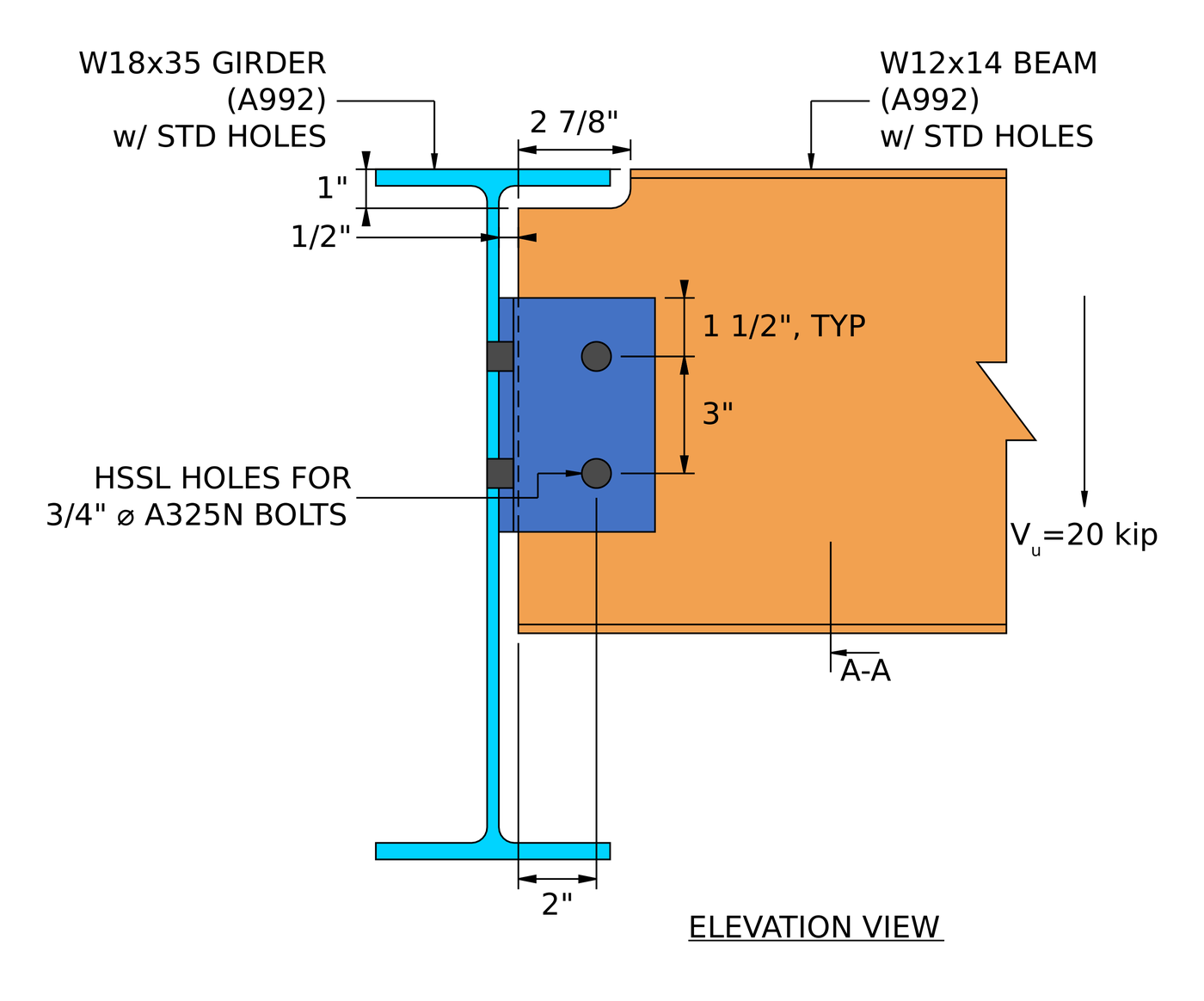
Elevación de la conexión de ejemplo.. The beam is coped 2 7/8 in long and 1 in deep at the top to clear the girder flange, con un 1/2 in clearance between the beam end and the girder web.
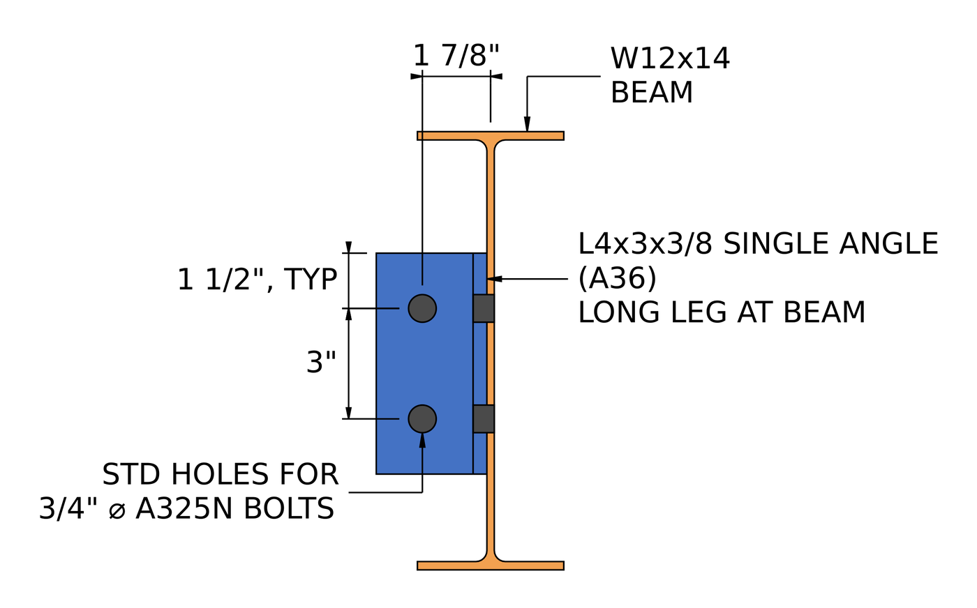
Sección A-A. The long leg is bolted to the beam web, y el 3 in outstanding leg is bolted to the girder web.
How do you design a single angle connection? Los pasos de un vistazo
- Verifique los límites de detalle en el lado de la viga.: espaciado, distancias al borde, profundidad, calibrar, cope.
- Check the beam-side bolt group in single shear.
- Check bolt bearing and tear-out on the angle at the beam side.
- Comprobar el cojinete de los pernos y el desgarro en el alma de la viga..
- cizalla combinada, rodamiento y desgarro por perno en el lado de la viga.
- Check block shear of the angle at the beam side.
- Check shear yielding and shear rupture of the angle at the beam side.
- Verifique la flexión del ángulo en el lado de la viga usando el procedimiento de doble copia..
- Check shear and moment interaction of the angle at the beam side.
- Check block shear of the coped beam web.
- Check shear yielding and shear rupture of the coped beam.
- Check flexure of the coped beam.
- Verifique los límites de detalle en el lado de soporte..
- Check the support-side bolt group with ICOR for its eccentricity.
- Check bolt bearing and tear-out on the angle at the support side.
- Check bolt bearing on the girder web.
- cizalla combinada, rodamiento y desgarro por perno en el lado de soporte.
- Check block shear of the angle at the support side.
- Check shear yielding and shear rupture of the angle at the support side.
- Compruebe la flexión del ángulo en el lado de soporte mediante el procedimiento de doble copia..
- Check shear and moment interaction of the angle at the support side.
Entradas de diseño para este ejemplo
El código de diseño es AISC. 360-16 LRFD. Las propiedades de la sección son del Manual AISC..
| Artículo | Símbolo | Valor |
|---|---|---|
| Corte vertical factorizado | [mathin] V_{u} [mathin] | 20 kip |
| Calculadora de | W12x14, A992 | |
| Profundidad del haz | [mathin] d_{bm} [mathin] | 11.9 in |
| Espesor del alma de la viga | [mathin] t_{wb} [mathin] | 0.2 in |
| Ancho del ala de la viga / grosor | [mathin] b_{fb},\ t_{fb} [mathin] | 3.97 in / 0.225 in |
| Área del haz | [mathin] A_{bm} [mathin] | 4.16 pulgadas² |
| Rendimiento del haz / tensión de tracción | [mathin] F_{yb},\ F_{ub} [mathin] | 50 KSI / 65 KSI |
| Top cope length / profundidad | [mathin] L_{ct},\ D_{ct} [mathin] | 2.875 in / 1 in |
| Girder | A18x35, A992 | |
| Girder depth / espesor de la red | [mathin] d_{sup},\ t_{ws} [mathin] | 17.7 in / 0.3 in |
| Girder flange width / grosor | [mathin] b_{fs},\ t_{fs} [mathin] | 6 in / 0.425 in |
| Girder area | [mathin] A_{sup} [mathin] | 10.3 pulgadas² |
| Girder yield / tensión de tracción | [mathin] F_{ys},\ F_{us} [mathin] | 50 KSI / 65 KSI |
| Módulo de elasticidad | [mathin] E [mathin] | 29000 KSI |
| Artículo | Símbolo | Valor |
|---|---|---|
| Ángulo | L4x3x3/8, A36, long leg at beam | |
| Profundidad del ángulo | [mathin] d_{a} [mathin] | 6 in |
| Grosor del ángulo | [mathin] t_{a} [mathin] | 0.375 in |
| Ancho de pierna en la viga / en soporte | [mathin] b_{a,NSL},\ b_{a,OSL} [mathin] | 4 in / 3 in |
| Rendimiento del ángulo / tensión de tracción | [mathin] F_{ya},\ F_{ua} [mathin] | 36 KSI / 58 KSI |
| Pernos (ambos lados) | 3/4 en A325-N | |
| Diámetro del perno | [mathin] d_{b} [mathin] | 0.75 in |
| Tracción nominal del perno / esfuerzo cortante | [mathin] F_{nt},\ F_{nv} [mathin] | 90 KSI / 54 KSI |
| Planos de corte, lado de la viga / lado de soporte | [mathin] N_{s} [mathin] | 1 / 1 |
| Agujeros en el lado de la viga (ángulo / viga) | Horizontal de ranura corta (HSSL) / para el (ETS) | |
| Orificios en el lado de soporte (ángulo / girder) | Estándar (ETS) / para el (ETS) |
| Geometría | Símbolo | Lado de la viga | Lado de soporte |
|---|---|---|---|
| Filas de pernos / espaciado entre filas | [mathin] n_{r},\ s_{r} [mathin] | 2 / 3 in | 2 / 3 in |
| Columnas de pernos / espaciado de columnas | [mathin] n_{c},\ s_{c} [mathin] | 1 / 0 in | 1 / 0 in |
| Calibrar | [mathin] g [mathin] | 2.5 in | 1.75 in |
| Distancia al borde vertical en ángulo | [mathin] L_{ev,a} [mathin] | 1.5 in | 1.5 in |
| Distancia al borde horizontal en ángulo | [mathin] L_{eh,a} [mathin] | 1.5 in | 1.25 in |
| Vertical edge distance at beam web | [mathin] L_{ev,bm} [mathin] | 3.575 in | |
| Excentricidad del perno | [mathin] e [mathin] | 2.5 in | 1.85 in |
| Beam web clearance to girder | [mathin] clr [mathin] | 0.5 in |
Paso 1: Detallando límites en el lado de la viga (AISC 360-16 J3.3, J3.4, J3.5)
Antes de cualquier control de fuerza, La disposición de los pernos debe ser edificable y coincidir con los supuestos detrás de las ecuaciones de resistencia.. Los pernos que están demasiado cerca se rompen entre los agujeros., Los bordes que están demasiado cerca se arrancan., and an angle that is too short or too deep changes how the connection rotates. The cope has to be deep enough to clear the girder flange.
Para 3/4 en perno el espacio mínimo es [mathin] 2\tfrac{2}{3} d_{b} = 2\,in [mathin] (J3.3) y la distancia mínima al borde es 1 in (Tabla J3.4). The beam-side leg has horizontal short-slotted holes, and the horizontal edge distance on the angle is measured across the end of the slot, por lo que el incremento de la Tabla J3.5 de 1/8 in for a short slot raises its minimum to 1.125 in. The horizontal edge distance on the beam web is the gage less the clearance, [mathin] 2.5\,in – 0.5\,in = 2\,in [mathin]. The angle has to be at least half as deep as the beam’s T dimension, so it is stiff enough to brace the beam end, y no más profundo que lo que la viga puede soportar. The bolt gage on the beam-side leg has to leave room to enter and tighten the bolts.
| Límite de detalles | Límite (in) | Actual (in) | DCR | Resultado |
|---|---|---|---|---|
| Distancia mínima entre filas de tornillos | 2.000 | 3.000 | 0.667 | PASAR |
| Distancia máxima entre filas de tornillos | 6.000 | 3.000 | 0.500 | PASAR |
| Ángulo distancia mínima al borde vertical | 1.000 | 1.500 | 0.667 | PASAR |
| Distancia mínima al borde horizontal del ángulo | 1.125 | 1.500 | 0.750 | PASAR |
| Distancia mínima al borde vertical de la viga | 1.000 | 3.575 | 0.280 | PASAR |
| Distancia mínima al borde horizontal de la viga | 1.000 | 2.000 | 0.500 | PASAR |
| Profundidad mínima de conexión | 5.188 | 6.000 | 0.865 | PASAR |
| Profundidad máxima de conexión | 10.000 | 6.000 | 0.600 | PASAR |
| Minimum bolt gage for single angle | 1.500 | 2.500 | 0.600 | PASAR |
| Minimum top cope depth | 0.750 | 1.000 | 0.750 | PASAR |
Para un límite mínimo, la relación es límite sobre real, y para un máximo es un límite real por encima. La fila gobernante es la profundidad mínima de conexión., la mitad del 10 3/8 in T dimension of the W12x14:
[math] DCR = \frac{d}{c} = \frac{(5.1875)}{(6)} = 0.86458 [math]
DCR = 0.865 < 1.0, OK
Paso 2: Cortante del grupo de tornillos en el lado de la viga (AISC 360-16 J3.6)
Each beam-side bolt passes through the angle and the beam web only, entonces tiene un plano de corte. The two bolts have to carry the full reaction between them.
Coeficiente del grupo de tornillos
The beam-side bolt line is 2.5 desde el ángulo del talón, pero aquí se ignora la excentricidad. Página del Manual AISC 10-116 permite esto para una sola fila vertical de pernos con una excentricidad de no más de 3 in, entonces el coeficiente del grupo de tornillos es simplemente el número de tornillos:
[math] C = 2 [math]
Fuerza del grupo de pernos
Dónde [mathin] \phi = 0.75 [mathin], [mathin] d_{b} = 0.75\,in [mathin], [mathin] F_{nv} = 54\,ksi [mathin] para un perno A325-N con roscas incluidas, [mathin] N_{s} = 1 [mathin] y [mathin] h_{f} = 1 [mathin] porque no hay rellenos (J5.2(a)):
[math] \phi R_{n} = \phi\, F_{nv}\, \frac{\pi}{4} \left( d_{b} \right)^{2} N_{s}\, C\, h_{f} [math]
[math] \phi R_{n} = (0.75) \times (54\,ksi) \times \frac{\pi}{4} \times \left( (0.75\,in) \right)^{2} \times (1) \times (2) \times (1) [math]
[math] \phi R_{n} = 35.785\,kip [math]
DCR = 20 kip / 35.785 salto = 0.559 < 1.0, OK
Paso 3: Bolt bearing and tear-out on the single angle at the beam side (AISC 360-16 J3.10)
Each beam-side bolt pushes on the edge of its hole in the angle. El ángulo se deforma en el agujero. (Llevando, limitado a 2.4 d t Fu) or tears a strip out to the next hole or to its lower edge (arrancar, 1.2 lc t Fu). The beam pushes the bolts down on the angle, entonces el perno inferior, más cercano al borde inferior del ángulo, es el débil.
The holes are short slots running horizontally and the load is vertical, so the hole dimension in the direction of the load is the standard [mathin] d_{h} = 0.8125\,in [mathin]. Distancia libre para el perno de borde, con [mathin] L_{ev,a} = 1.5\,in [mathin]:
[math] l_{c1} = L_{ev,a} – \frac{d_{h}}{2} = (1.5\,in) – \frac{(0.8125\,in)}{2} = 1.0938\,in [math]
Clear distance between bolts, con [mathin] s_{r} = 3\,in [mathin]:
[math] l_{c2} = s_{r} – d_{h} = (3\,in) – (0.8125\,in) = 2.1875\,in [math]
Dónde [mathin] t_{a} = 0.375\,in [mathin], [mathin] F_{ua} = 58\,ksi [mathin], [mathin] C = 2 [mathin] y [mathin] n_{r} = 2 [mathin]:
[math] \phi R_{n} = \phi \left[ \min\left(1.2\, l_{c1},\, 2.4\, d_{b}\right) t_{a} F_{ua} + \min\left(1.2\, l_{c2},\, 2.4\, d_{b}\right) t_{a} F_{ua} \left( n_{r} – 1 \right) \right] \left( \frac{C}{n_{r}} \right) [math]
[math] \phi R_{n} = (0.75) \times \left[ \min\left(1.2 \times (1.0938\,in),\, 2.4 \times (0.75\,in)\right) \times (0.375\,in) \times (58\,ksi) + \min\left(1.2 \times (2.1875\,in),\, 2.4 \times (0.75\,in)\right) \times (0.375\,in) \times (58\,ksi) \times \left( (2) – 1 \right) \right] \times \left( \frac{(2)}{(2)} \right) [math]
[math] \phi R_{n} = 50.773\,kip [math]
DCR = 20 kip / 50.773 salto = 0.394 < 1.0, OK
El desgarro controla el perno de borde, porque 1.2 lc1 es menor que 2.4 db. The other bolt is limited by bearing.
Paso 4: Soporte de pernos y desgarro en el alma de la viga (AISC 360-16 J3.10)
La misma verificación se aplica al alma de la viga.. Here the web moves down against bolts held by the angle, so the bolts bear on the top of the web holes, and the edge bolt is the top one, 3.575 in below the cut edge of the cope.
Clear distance for the top bolt, con [mathin] L_{ev,bm} = 3.575\,in [mathin] y [mathin] d_{h} = 0.8125\,in [mathin]:
[math] l_{c1} = L_{ev,bm} – \frac{d_{h}}{2} = (3.575\,in) – \frac{(0.8125\,in)}{2} = 3.1688\,in [math]
[math] l_{c2} = s_{r} – d_{h} = (3\,in) – (0.8125\,in) = 2.1875\,in [math]
Dónde [mathin] t_{wb} = 0.2\,in [mathin], [mathin] F_{ub} = 65\,ksi [mathin], [mathin] C = 2 [mathin] y [mathin] n_{r} = 2 [mathin]:
[math] \phi R_{n} = \phi \left[ \min\left(1.2\, l_{c1},\, 2.4\, d_{b}\right) t_{wb} F_{ub} + \min\left(1.2\, l_{c2},\, 2.4\, d_{b}\right) t_{wb} F_{ub} \left( n_{r} – 1 \right) \right] \left( \frac{C}{n_{r}} \right) [math]
[math] \phi R_{n} = (0.75) \times \left[ \min\left(1.2 \times (3.1688\,in),\, 2.4 \times (0.75\,in)\right) \times (0.2\,in) \times (65\,ksi) + \min\left(1.2 \times (2.1875\,in),\, 2.4 \times (0.75\,in)\right) \times (0.2\,in) \times (65\,ksi) \times \left( (2) – 1 \right) \right] \times \left( \frac{(2)}{(2)} \right) [math]
[math] \phi R_{n} = 35.1\,kip [math]
DCR = 20 kip / 35.1 salto = 0.570 < 1.0, OK
Both bolts are capped by bearing at 2.4 db, because the long edge distance below the cope keeps tear-out out of play. El 0.2 en la web es más delgado que el 3/8 in angle, so it is the weaker ply on the beam side.
Paso 5: Resistencia efectiva del grupo de tornillos en el lado de la viga (AISC 360-16 J3.6 Comentario)
Cizalla de perno, El rodamiento y el desmontaje no son realmente controles separados.. Cada perno lleva la menor parte de su resistencia al corte y su resistencia al desgarro en cada capa por la que pasa., y la fuerza del grupo es la suma de esos valores por perno.
Strength of one bolt in single shear:
[math] \phi r_{v} = \phi\, F_{nv}\, \frac{\pi}{4} \left( d_{b} \right)^{2} N_{s}\, h_{f} = (0.75) \times (54\,ksi) \times \frac{\pi}{4} \times \left( (0.75\,in) \right)^{2} \times (1) \times (1) = 17.892\,kip [math]
Bearing and tear-out of one bolt on the angle, for the edge bolt and the inner bolt:
[math] \phi r_{n1e} = \phi\, \min\left(1.2\, l_{c1},\, 2.4\, d_{b}\right) t_{a} F_{ua} = (0.75) \times \min\left(1.2 \times (1.0938\,in),\, 2.4 \times (0.75\,in)\right) \times (0.375\,in) \times (58\,ksi) = 21.41\,kip [math]
[math] \phi r_{n1i} = \phi\, \min\left(1.2\, l_{c2},\, 2.4\, d_{b}\right) t_{a} F_{ua} = (0.75) \times \min\left(1.2 \times (2.1875\,in),\, 2.4 \times (0.75\,in)\right) \times (0.375\,in) \times (58\,ksi) = 29.363\,kip [math]
Apoyo y desprendimiento de un perno en el alma de la viga, for the edge bolt and the inner bolt:
[math] \phi r_{n2e} = \phi\, \min\left(1.2\, l_{c1},\, 2.4\, d_{b}\right) t_{wb} F_{ub} = (0.75) \times \min\left(1.2 \times (3.1688\,in),\, 2.4 \times (0.75\,in)\right) \times (0.2\,in) \times (65\,ksi) = 17.55\,kip [math]
[math] \phi r_{n2i} = \phi\, \min\left(1.2\, l_{c2},\, 2.4\, d_{b}\right) t_{wb} F_{ub} = (0.75) \times \min\left(1.2 \times (2.1875\,in),\, 2.4 \times (0.75\,in)\right) \times (0.2\,in) \times (65\,ksi) = 17.55\,kip [math]
Los pernos están numerados desde la parte superior de la línea.. Tornillo 1 is the edge bolt on the beam web and an inner bolt on the angle; tornillo 2 is the edge bolt on the angle:
[math] \phi r_{eff,1} = \min\left( \phi r_{v},\, \phi r_{n1i},\, \phi r_{n2e} \right) = \min\left( (17.892\,kip),\, (29.363\,kip),\, (17.55\,kip) \right) = 17.55\,kip [math]
[math] \phi r_{eff,2} = \min\left( \phi r_{v},\, \phi r_{n1e},\, \phi r_{n2i} \right) = \min\left( (17.892\,kip),\, (21.41\,kip),\, (17.55\,kip) \right) = 17.55\,kip [math]
| Tornillo | Cizalla de perno (kip) | Mediante el último botón del menú lateral izquierdo se puede modificar el valor de la carga de recargo / arrancar, ángulo único (kip) | Mediante el último botón del menú lateral izquierdo se puede modificar el valor de la carga de recargo / arrancar, viga web (kip) | Fuerza efectiva (kip) |
|---|---|---|---|---|
| 1 | 17.89 | 29.36 | 17.55 | 17.55 |
| 2 | 17.89 | 21.41 | 17.55 | 17.55 |
[math] \sum \phi r_{eff} = n_{1}\, \phi r_{eff,1} + n_{2}\, \phi r_{eff,2} = (1) \times (17.55\,kip) + (1) \times (17.55\,kip) = 35.1\,kip [math]
[math] \phi R_{n,eff} = \left( \frac{C}{n_{r}} \right) \sum \phi r_{eff} = \left( \frac{(2)}{(2)} \right) \times (35.1\,kip) = 35.1\,kip [math]
DCR = 20 kip / 35.1 salto = 0.570 < 1.0, OK
Bearing on the beam web governs both bolts, though bolt shear is only 2% más alto. Puede ejecutar la misma conexión en el calculadora de diseño de conexión gratuita and try a third bolt row to see how the ratio moves.
Paso 6: Block shear of the single angle at the beam side (AISC 360-16 J4.3)
A block of the angle can tear out along the bolt line: shear down the line of holes, más tensión hasta el borde libre del ángulo. Con una columna de pernos, se trata de un bloque en forma de L..
Área neta en tensión. The tension plane runs horizontally, a lo largo de las ranuras, entonces usa la longitud de la ranura [mathin] d_{h} = 1\,in [mathin], con [mathin] t_{a} = 0.375\,in [mathin], [mathin] n_{c} = 1 [mathin], [mathin] s_{c} = 0\,in [mathin] y [mathin] L_{eh,a} = 1.5\,in [mathin]. Cada agujero suma 1/16 en busca de daños durante el punzonado (B4.3):
[math] A_{nt} = t_{a} \left[ (n_{c}-1)\, s_{c} + L_{eh,a} – (n_{c} – 0.5)\left( d_{h} + 0.0625\,in \right) \right] [math]
[math] A_{nt} = (0.375\,in) \times \left[ ((1)-1) \times (0\,in) + (1.5\,in) – ((1) – 0.5) \times ((1\,in) + (0.0625\,in)) \right] = 0.36328\,in^{2} [math]
Áreas brutas y netas en corte. The shear plane runs vertically, a través de las ranuras, so it uses [mathin] d_{h} = 0.8125\,in [mathin]:
[math] A_{gv} = t_{a} \left[ L_{ev,a} + (n_{r}-1)\, s_{r} \right] = (0.375\,in) \times \left[ (1.5\,in) + ((2)-1) \times (3\,in) \right] = 1.6875\,in^{2} [math]
[math] A_{nv} = t_{a} \left[ d_{a} – L_{ev,a} – (n_{r} – 0.5)\left( d_{h} + 0.0625\,in \right) \right] [math]
[math] A_{nv} = (0.375\,in) \times \left[ (6\,in) – (1.5\,in) – ((2) – 0.5) \times ((0.8125\,in) + (0.0625\,in)) \right] = 1.1953\,in^{2} [math]
Resistencia al corte del bloque, con [mathin] U_{bs} = 1 [mathin] para una tensión uniforme, [mathin] F_{ua} = 58\,ksi [mathin], [mathin] F_{ya} = 36\,ksi [mathin] y [mathin] \phi = 0.75 [mathin]:
[math] \phi R_{n} = \phi \left( 0.6\, F_{ua} A_{nv} + U_{bs} F_{ua} A_{nt} \le 0.6\, F_{ya} A_{gv} + U_{bs} F_{ua} A_{nt} \right) [math]
[math] \phi R_{n} = (0.75) \times \left( 0.6 \times (58\,ksi) \times (1.1953\,in^{2}) + (1) \times (58\,ksi) \times (0.36328\,in^{2}) \le 0.6 \times (36\,ksi) \times (1.6875\,in^{2}) + (1) \times (58\,ksi) \times (0.36328\,in^{2}) \right) [math]
[math] \phi R_{n} = 43.14\,kip [math]
DCR = 20 kip / 43.14 salto = 0.464 < 1.0, OK
El lado de la ecuación que cede al corte gobierna. A36 tiene una baja relación entre rendimiento y tracción., por lo que el plano de corte bruto cede antes de que el plano de corte neto se rompa.
Paso 7: Shear yielding and shear rupture of the single angle at the beam side (AISC 360-16 J4.2)
The full reaction passes down through the angle leg as vertical shear. La sección bruta no debe ceder, y la sección de la red a través de los orificios de los pernos no debe romperse.
Rendimiento al corte (Eq. J4-3)
[math] A_{gv} = d_{a}\, t_{a} = (6\,in) \times (0.375\,in) = 2.25\,in^{2} [math]
[math] \phi R_{n,sy} = \phi\, 0.6\, F_{ya} A_{gv} = (1) \times 0.6 \times (36\,ksi) \times (2.25\,in^{2}) = 48.6\,kip [math]
ruptura por corte (Eq. J4-4)
[math] A_{nv} = t_{a} \left[ d_{a} – n_{r}\left( d_{h} + 0.0625\,in \right) \right] = (0.375\,in) \times \left[ (6\,in) – (2) \times ((0.8125\,in) + (0.0625\,in)) \right] = 1.5938\,in^{2} [math]
[math] \phi R_{n,sr} = \phi\, 0.6\, F_{ua} A_{nv} = (0.75) \times 0.6 \times (58\,ksi) \times (1.5938\,in^{2}) = 41.597\,kip [math]
[math] \phi R_{n} = \min\left( \phi R_{n,sy},\, \phi R_{n,sr} \right) = \min\left( (48.6\,kip),\, (41.597\,kip) \right) = 41.597\,kip [math]
DCR = 20 kip / 41.597 salto = 0.481 < 1.0, OK
Paso 8: Flexure of the single angle at the beam side, procedimiento de doble copia (AISC 360-16 F11.2)
La reacción se lleva desde la línea de pernos del lado de la viga hasta el talón del ángulo., so the leg acts as a short cantilever plate in bending. Una profunda, la pierna delgada puede doblarse hacia un lado antes de ceder. El Manual AISC maneja esto con el procedimiento para una viga revestida en ambas alas., treating the leg like a beam web with the flanges cut away. La longitud no arriostrada es el calibre del lado de la viga., [mathin] L_{b} = 2.5\,in [mathin]. The leg is also checked for flexural rupture through the bolt holes.
Comprobación de rango
Dónde [mathin] E = 29000\,ksi [mathin], [mathin] F_{ya} = 36\,ksi [mathin], [mathin] d_{a} = 6\,in [mathin] y [mathin] t_{a} = 0.375\,in [mathin]:
[math] \frac{L_{b} d}{t^{2}} = \frac{(2.5\,in) \times (6\,in)}{(0.375\,in)^{2}} = 106.67 [math]
[math] \frac{0.08 E}{F_{y}} = \frac{0.08 \times (29000\,ksi)}{(36\,ksi)} = 64.444 \qquad \frac{1.9 E}{F_{y}} = \frac{1.9 \times (29000\,ksi)}{(36\,ksi)} = 1530.6 [math]
Entonces [mathin] \frac{0.08E}{F_{y}} \lt \frac{L_{b} d}{t^{2}} \le \frac{1.9E}{F_{y}} [mathin], Determine la deflexión y el ángulo de rotación en el extremo B de la viga mostrada en la figura. Se aplica F11-2.
Section moduli of the angle leg
[math] Z = \frac{t_{a} \left( d_{a} \right)^{2}}{4} = \frac{(0.375\,in) \times ((6\,in))^{2}}{4} = 3.375\,in^{3} [math]
[math] S = \frac{t_{a} \left( d_{a} \right)^{2}}{6} = \frac{(0.375\,in) \times ((6\,in))^{2}}{6} = 2.25\,in^{3} [math]
Factor de modificación de pandeo lateral-torsional (Ecuación manual AISC. 9-15)
With no cope on the angle, [mathin] d_{ct} = 0\,in [mathin]:
[math] C_{b} = \left[ 3 + \ln\left( \frac{L_{b}}{d_{a}} \right) \right] \left( 1 – \frac{d_{ct}}{d_{a}} \right) \ge 1.84 [math]
[math] C_{b} = \left[ 3 + \ln\left( \frac{(2.5\,in)}{(6\,in)} \right) \right] \times \left( 1 – \frac{(0\,in)}{(6\,in)} \right) \ge 1.84 [math]
[math] C_{b} = 2.1245 [math]
Flexural yielding and buckling strength
Con [mathin] \phi = 0.9 [mathin]:
[math] \phi M_{n} = \phi \left[ C_{b} \left[ 1.52 – 0.274 \left( \frac{L_{b} d}{t^{2}} \right) \left( \frac{F_{ya}}{E} \right) \right] F_{ya} S \le F_{ya} Z \right] [math]
[math] \phi M_{n} = (0.9) \times \left[ (2.1245) \times \left[ 1.52 – 0.274 \times ((106.67)) \times \left( \frac{(36\,ksi)}{(29000\,ksi)} \right) \right] \times (36\,ksi) \times (2.25\,in^{3}) \le (36\,ksi) \times (3.375\,in^{3}) \right] [math]
[math] \phi M_{n} = 9.1125\,kip\text{-}ft \;(109.35\,kip\text{-}in) [math]
La tapa del momento de plástico [mathin] F_{ya} Z [mathin] gobierna, so the leg is not prone to buckling at this depth and thickness. The equivalent shear capacity is:
[math] \phi V_{n,y} = \frac{\phi M_{n}}{L_{b}} = \frac{(9.1125\,kip\text{-}ft)}{(2.5\,in)} = 43.74\,kip [math]
ruptura por flexión (Parte del manual AISC 15 Tabla 15-3, Parte 9 Eq. 9-4)
The net plastic section modulus removes the bolt holes, con [mathin] d_{h} = 0.8125\,in [mathin] y [mathin] s_{r} = 3\,in [mathin]. With an even number of rows the last term is zero:
[math] Z_{net} = \frac{t_{a} \left( d_{a} \right)^{2}}{4} – t_{a} \left( d_{h} + 0.0625\,in \right) s_{r} \left\lfloor \frac{n_{r}^{2}}{4} \right\rfloor – \left[ n_{r}\ \text{odd} \right] \frac{t_{a} \left( d_{h} + 0.0625\,in \right)^{2}}{4} [math]
[math] Z_{net} = \frac{(0.375\,in) \times ((6\,in))^{2}}{4} – (0.375\,in) \times ((0.8125\,in) + (0.0625\,in)) \times (3\,in) \times \left\lfloor \frac{(2)^{2}}{4} \right\rfloor – \left[ (2)\ \text{odd} \right] \times \frac{(0.375\,in) \times ((0.8125\,in) + (0.0625\,in))^{2}}{4} = 2.3906\,in^{3} [math]
[math] \phi M_{n} = \phi\, F_{ua} Z_{net} = (0.75) \times (58\,ksi) \times (2.3906\,in^{3}) = 8.666\,kip\text{-}ft [math]
[math] \phi V_{n,r} = \frac{\phi M_{n}}{L_{b}} = \frac{(8.666\,kip\text{-}ft)}{(2.5\,in)} = 41.597\,kip [math]
Governing flexural capacity
[math] \phi V_{n} = \min\left( \phi V_{n,y},\, \phi V_{n,r} \right) = \min\left( (43.74\,kip),\, (41.597\,kip) \right) = 41.597\,kip [math]
DCR = 20 kip / 41.597 salto = 0.481 < 1.0, OK
Flexural rupture governs. It happens to give the same 41.597 kip as shear rupture in Step 7.
Paso 9: Shear and moment interaction of the single angle at the beam side (Ecuación manual AISC. 10-5)
The angle leg carries shear and bending at the same section at the same time, entonces los dos tienen que ser revisados juntos. El Manual utiliza una interacción circular entre la resistencia a la fluencia al corte y la resistencia a la flexión..
El momento en el ángulo es la reacción multiplicada por la longitud no arriostrada, con [mathin] V_{r} = 20\,kip [mathin] y [mathin] L_{b} = 2.5\,in [mathin]:
[math] M_{r} = V_{r}\, L_{b} = (20\,kip) \times (2.5\,in) = 4.1667\,kip\text{-}ft [math]
Con [mathin] \phi V_{n} = 48.6\,kip [mathin] de fluencia por corte en el paso 7 y [mathin] \phi M_{n} = 9.1125\,kip\text{-}ft [mathin] desde el paso 8:
[math] I_{nt} = \left( \frac{V_{r}}{\phi V_{n}} \right)^{2} + \left( \frac{M_{r}}{\phi M_{n}} \right)^{2} [math]
[math] I_{nt} = \left( \frac{(20\,kip)}{(48.6\,kip)} \right)^{2} + \left( \frac{(4.1667\,kip\text{-}ft)}{(9.1125\,kip\text{-}ft)} \right)^{2} = 0.37843 [math]
DCR = 0.37843 / 1.0 = 0.378 < 1.0, OK
Paso 10: Block shear of the coped beam web (AISC 360-16 J4.3)
The top cope removes the beam’s top flange at the connection, so a block of the web can tear out along the bolt line: shear up the line of holes to the cut edge of the cope, plus tension across to the beam end.
Área neta en tensión, con [mathin] t_{wb} = 0.2\,in [mathin], [mathin] L_{eh,bm} = 2\,in [mathin] and the standard hole [mathin] d_{h} = 0.8125\,in [mathin]:
[math] A_{nt} = t_{wb} \left[ (n_{c}-1)\, s_{c} + L_{eh,bm} – (n_{c} – 0.5)\left( d_{h} + 0.0625\,in \right) \right] [math]
[math] A_{nt} = (0.2\,in) \times \left[ ((1)-1) \times (0\,in) + (2\,in) – ((1) – 0.5) \times ((0.8125\,in) + (0.0625\,in)) \right] = 0.3125\,in^{2} [math]
Gross area in shear, from the cope edge down to the bottom bolt, con [mathin] L_{ev,bm} = 3.575\,in [mathin]:
[math] A_{gv} = t_{wb} \left[ L_{ev,bm} + (n_{r}-1)\, s_{r} \right] = (0.2\,in) \times \left[ (3.575\,in) + ((2)-1) \times (3\,in) \right] = 1.315\,in^{2} [math]
Net area in shear. The report writes it with a depth term [mathin] d_{coped} = 10.15\,in [mathin]; the bracket [mathin] d_{coped} – L_{ev,bm} = 6.575\,in [mathin] is the same shear plane length as in the gross area:
[math] A_{nv} = t_{wb} \left[ d_{coped} – L_{ev,bm} – (n_{r} – 0.5)\left( d_{h} + 0.0625\,in \right) \right] [math]
[math] A_{nv} = (0.2\,in) \times \left[ (10.15\,in) – (3.575\,in) – ((2) – 0.5) \times ((0.8125\,in) + (0.0625\,in)) \right] = 1.0525\,in^{2} [math]
Con [mathin] F_{ub} = 65\,ksi [mathin], [mathin] F_{yb} = 50\,ksi [mathin], [mathin] U_{bs} = 1 [mathin] y [mathin] \phi = 0.75 [mathin]:
[math] \phi R_{n} = \phi \left( 0.6\, F_{ub} A_{nv} + U_{bs} F_{ub} A_{nt} \le 0.6\, F_{yb} A_{gv} + U_{bs} F_{ub} A_{nt} \right) [math]
[math] \phi R_{n} = (0.75) \times \left( 0.6 \times (65\,ksi) \times (1.0525\,in^{2}) + (1) \times (65\,ksi) \times (0.3125\,in^{2}) \le 0.6 \times (50\,ksi) \times (1.315\,in^{2}) + (1) \times (65\,ksi) \times (0.3125\,in^{2}) \right) [math]
[math] \phi R_{n} = 44.822\,kip [math]
DCR = 20 kip / 44.822 salto = 0.446 < 1.0, OK
Paso 11: Shear yielding and shear rupture of the coped beam (AISC 360-16 J4.2)
At the cope, the full reaction passes through the web that is left below the cut, without the top flange. That reduced web is checked for shear yielding on its gross area and shear rupture through the bolt holes.
The depth of web remaining is the beam depth less the cope depth, [mathin] d_{coped} = 11.9\,in – 1\,in = 10.9\,in [mathin].
Rendimiento al corte (Eq. J4-3)
[math] A_{gv} = d_{coped}\, t_{wb} = (10.9\,in) \times (0.2\,in) = 2.18\,in^{2} [math]
[math] \phi R_{n,sy} = \phi\, 0.6\, F_{yb} A_{gv} = (1) \times 0.6 \times (50\,ksi) \times (2.18\,in^{2}) = 65.4\,kip [math]
ruptura por corte (Eq. J4-4)
[math] A_{nv} = t_{wb} \left[ d_{coped} – n_{r}\left( d_{h} + 0.0625\,in \right) \right] = (0.2\,in) \times \left[ (10.9\,in) – (2) \times ((0.8125\,in) + (0.0625\,in)) \right] = 1.83\,in^{2} [math]
[math] \phi R_{n,sr} = \phi\, 0.6\, F_{ub} A_{nv} = (0.75) \times 0.6 \times (65\,ksi) \times (1.83\,in^{2}) = 53.528\,kip [math]
[math] \phi R_{n} = \min\left( (65.4\,kip),\, (53.528\,kip) \right) = 53.528\,kip [math]
DCR = 20 kip / 53.528 salto = 0.374 < 1.0, OK
Paso 12: Flexure of the coped beam (Parte del manual AISC 9, Eq. 9-7)
The reaction acts at the beam end, so the coped section at the inside face of the cope carries a moment equal to the reaction times its distance from the bolts. Without its top flange the web there is a tee with an unbraced top edge in compression, which can buckle locally. The Manual’s coped beam procedure checks the web slenderness against a limit that depends on the cope geometry.
Entradas: [mathin] F_{yb} = 50\,ksi [mathin], [mathin] D_{ct} = 1\,in [mathin], [mathin] c = L_{ct} = 2.875\,in [mathin], no bottom cope, [mathin] \phi = 0.9 [mathin]. The section moduli of the tee remaining at the cope are [mathin] S_{x} = 5.6132\,in^{3} [mathin] y [mathin] Z_{x} = 9.5686\,in^{3} [mathin].
Web slenderness (Eq. 9-11)
[math] \lambda = \frac{h_{o}}{t_{wb}} = \frac{(10.9\,in)}{(0.2\,in)} = 54.5 [math]
Buckling adjustment factor (Eq. 9-14a) and plate buckling coefficient (Eq. 9-13a)
Ya que [mathin] c \le d_{bm} [mathin] y [mathin] c \le h_{o} [mathin]:
[math] f = 2 \left( \frac{c}{d_{bm}} \right) = 2 \times \left( \frac{(2.875\,in)}{(11.9\,in)} \right) = 0.48319 [math]
[math] k = 2.2 \left( \frac{h_{o}}{c} \right)^{1.65} = 2.2 \times \left( \frac{(10.9\,in)}{(2.875\,in)} \right)^{1.65} = 19.835 [math]
Limiting slenderness for a compact web (Eq. 9-12)
[math] \lambda_{p} = 0.475 \sqrt{\frac{\left( f k \ge 1.61 \right) E}{F_{yb}}} [math]
[math] \lambda_{p} = 0.475 \times \sqrt{\frac{\left( (0.48319) \times (19.835) \ge 1.61 \right) \times (29000\,ksi)}{(50\,ksi)}} = 35.414 [math]
Resistencia a la flexión (Eq. 9-7)
Ya que [mathin] \lambda_{p} \lt \lambda \le 2\lambda_{p} [mathin], the web is noncompact and the strength is interpolated between the plastic and elastic moments:
[math] \phi M_{n} = \phi \left[ F_{yb} Z_{x} – \left( F_{yb} Z_{x} – F_{yb} S_{x} \right) \left( \frac{\lambda}{\lambda_{p}} – 1 \right) \right] [math]
[math] \phi M_{n} = (0.9) \times \left[ (50\,ksi) \times (9.5686\,in^{3}) – \left( (50\,ksi) \times (9.5686\,in^{3}) – (50\,ksi) \times (5.6132\,in^{3}) \right) \times \left( \frac{(54.5)}{(35.414)} – 1 \right) \right] [math]
[math] \phi M_{n} = 27.889\,kip\text{-}ft [math]
Capacidad de corte equivalente
The lever arm is the cope eccentricity, the cope length plus the beam end clearance, [mathin] e_{c} = 2.875\,in + 0.5\,in = 3.375\,in [mathin]:
[math] \phi V_{n} = \frac{\phi M_{n}}{e_{c}} = \frac{(27.889\,kip\text{-}ft)}{(3.375\,in)} = 99.16\,kip [math]
DCR = 20 kip / 99.16 salto = 0.202 < 1.0, OK
Paso 13: Detallando límites en el lado de soporte. (AISC 360-16 J3.3, J3.4, J3.5)
The outstanding leg is bolted to the girder web, por lo que se aplican las mismas reglas de espaciado y borde, plus a gage limit that keeps the bolts far enough out from the beam web to be entered and tightened. The angle holes here are standard, so the horizontal edge distance minimum is the plain 1 de la Tabla J3.4. The actual edge distance is what is left of the 3 in leg outside the 1.75 en calibre, 1.25 in.
| Límite de detalles | Límite (in) | Actual (in) | DCR | Resultado |
|---|---|---|---|---|
| Distancia mínima entre filas de tornillos | 2.000 | 3.000 | 0.667 | PASAR |
| Distancia máxima entre filas de tornillos | 6.000 | 3.000 | 0.500 | PASAR |
| Ángulo distancia mínima al borde vertical | 1.000 | 1.500 | 0.667 | PASAR |
| Distancia mínima al borde horizontal del ángulo | 1.000 | 1.250 | 0.800 | PASAR |
| Minimum bolt gage for single angle | 1.500 | 1.750 | 0.857 | PASAR |
The governing row is the minimum bolt gage:
[math] DCR = \frac{d}{c} = \frac{(1.5)}{(1.75)} = 0.85714 [math]
DCR = 0.857 < 1.0, OK
Paso 14: Bolt group shear at the support side by the instantaneous center of rotation (AISC 360-16 J3.6)
This is where a single angle differs most from a double angle. The beam web sits to one side of the support bolt line, so the reaction reaches the girder bolts 1.85 in off their line, and the two bolts carry a moment as well as the shear. El centro instantáneo de rotación. (ICOR) El método encuentra el punto sobre el que gira el grupo de tornillos y lo convierte en un coeficiente C., the number of bolts’ Valor de resistencia al corte que el grupo realmente ofrece..
Excentricidad del diseño
The eccentricity is the support gage plus half the beam web, measured to the beam web centreline:
[math] e = g + \frac{t_{wb}}{2} = 1.75\,in + \frac{0.2\,in}{2} = 1.85\,in [math]
Fuerza de un perno
[math] \phi r_{v} = \phi\, F_{nv}\, \frac{\pi}{4} \left( d_{b} \right)^{2} N_{s}\, h_{f} = 17.892\,kip [math]
Localizando el centro instantáneo
Tornillo 1 está al final de la línea, con las coordenadas siguientes. El IC se encuentra por iteración., utilizando la curva carga-deformación de la ecuación manual AISC (7-1) en las páginas 7-6 a 7-8. El Cálculo del grupo de tornillos usando ICOR recorre esa iteración en su totalidad.
| Tornillo | x (in) | y (in) |
|---|---|---|
| 1 | 0.00 | 0.00 |
| 2 | 0.00 | 3.00 |
La iteración converge con el IC en:
[math] x_{ic} = -1.2162\,in, \qquad y_{ic} = 1.5\,in [math]
Las reacciones del perno en ese lugar son:
| Tornillo | R (kip) | Rx (kip) | Ry (kip) | Minnesota (pollo en) |
|---|---|---|---|---|
| 1 | 17.56 | 13.64 | 11.06 | 33.91 |
| 2 | 17.56 | -13.64 | 11.06 | 33.91 |
That gives the bolt group coefficient:
[math] C = 1.24 [math]
Fuerza del grupo de pernos
Con [mathin] N_{s} = 1 [mathin], [mathin] h_{f} = 1 [mathin] (J5.2(a)) y [mathin] \phi = 0.75 [mathin]:
[math] \phi R_{n} = \phi\, F_{nv}\, \frac{\pi}{4} \left( d_{b} \right)^{2} N_{s}\, C\, h_{f} [math]
[math] \phi R_{n} = (0.75) \times (54\,ksi) \times \frac{\pi}{4} \times \left( (0.75\,in) \right)^{2} \times (1) \times (1.24) \times (1) [math]
[math] \phi R_{n} = 22.187\,kip [math]
DCR = 20 kip / 22.187 salto = 0.901 < 1.0, OK
This is the governing check in the connection. With only two bolts 3 en aparte, a 1.85 in eccentricity cuts the group from 2 tornillos’ worth of strength to 1.24, a 38% pérdida.
Paso 15: Bolt bearing and tear-out on the single angle at the support side (AISC 360-16 J3.10)
On the support side the angle is pushed down while the girder web holds the bolts in place, de modo que los pernos se apoyen hacia arriba en los orificios angulares. El perno superior, más cercano al borde superior del ángulo, ¿Está el perno de borde aquí?. The group strength is scaled by C/n to account for the eccentricity.
[math] l_{c1} = L_{ev,a} – \frac{d_{h}}{2} = (1.5\,in) – \frac{(0.8125\,in)}{2} = 1.0938\,in [math]
[math] l_{c2} = s_{r} – d_{h} = (3\,in) – (0.8125\,in) = 2.1875\,in [math]
Dónde [mathin] t_{a} = 0.375\,in [mathin], [mathin] F_{ua} = 58\,ksi [mathin], [mathin] C = 1.24 [mathin] y [mathin] n_{r} = 2 [mathin]:
[math] \phi R_{n} = \phi \left[ \min\left(1.2\, l_{c1},\, 2.4\, d_{b}\right) t_{a} F_{ua} + \min\left(1.2\, l_{c2},\, 2.4\, d_{b}\right) t_{a} F_{ua} \left( n_{r} – 1 \right) \right] \left( \frac{C}{n_{r}} \right) [math]
[math] \phi R_{n} = (0.75) \times \left[ \min\left(1.2 \times (1.0938\,in),\, 2.4 \times (0.75\,in)\right) \times (0.375\,in) \times (58\,ksi) + \min\left(1.2 \times (2.1875\,in),\, 2.4 \times (0.75\,in)\right) \times (0.375\,in) \times (58\,ksi) \times \left( (2) – 1 \right) \right] \times \left( \frac{(1.24)}{(2)} \right) [math]
[math] \phi R_{n} = 31.479\,kip [math]
DCR = 20 kip / 31.479 salto = 0.635 < 1.0, OK
Paso 16: Bolt bearing on the girder web (AISC 360-16 J3.10)
The bolts also bear on the girder web. The girder runs past the connection in both directions, por lo que no hay borde que romper y cada perno se apoya como un perno interior.
[math] l_{c2} = s_{r} – d_{h} = (3\,in) – (0.8125\,in) = 2.1875\,in [math]
Dónde [mathin] t_{ws} = 0.3\,in [mathin], [mathin] F_{us} = 65\,ksi [mathin] y [mathin] C = 1.24 [mathin]:
[math] \phi R_{n} = \phi\, \min\left(1.2\, l_{c2},\, 2.4\, d_{b}\right) t_{ws} F_{us}\, C [math]
[math] \phi R_{n} = (0.75) \times \min\left(1.2 \times (2.1875\,in),\, 2.4 \times (0.75\,in)\right) \times (0.3\,in) \times (65\,ksi) \times (1.24) [math]
[math] \phi R_{n} = 32.643\,kip [math]
DCR = 20 kip / 32.643 salto = 0.613 < 1.0, OK
Paso 17: Resistencia efectiva del grupo de tornillos en el lado del soporte. (AISC 360-16 J3.6 Comentario)
Como en el lado de la viga, cada perno ofrece la menor cantidad de su resistencia al corte y su resistencia al rodamiento o al desgarro en cada capa, y la fuerza del grupo es la suma, scaled here by C/n for the eccentricity.
[math] \phi r_{v} = \phi\, F_{nv}\, \frac{\pi}{4} \left( d_{b} \right)^{2} N_{s}\, h_{f} = (0.75) \times (54\,ksi) \times \frac{\pi}{4} \times \left( (0.75\,in) \right)^{2} \times (1) \times (1) = 17.892\,kip [math]
Bearing and tear-out of one bolt on the angle, for the edge bolt and the inner bolt:
[math] \phi r_{n1e} = (0.75) \times \min\left(1.2 \times (1.0938\,in),\, 2.4 \times (0.75\,in)\right) \times (0.375\,in) \times (58\,ksi) = 21.41\,kip [math]
[math] \phi r_{n1i} = (0.75) \times \min\left(1.2 \times (2.1875\,in),\, 2.4 \times (0.75\,in)\right) \times (0.375\,in) \times (58\,ksi) = 29.363\,kip [math]
Bearing of one bolt on the girder web:
[math] \phi r_{n2} = \phi\, \min\left(1.2\, l_{c2},\, 2.4\, d_{b}\right) t_{ws} F_{us} = (0.75) \times \min\left(1.2 \times (2.1875\,in),\, 2.4 \times (0.75\,in)\right) \times (0.3\,in) \times (65\,ksi) = 26.325\,kip [math]
Los pernos están numerados desde la parte superior de la línea., así que perno 1 es el perno de borde en el lado de soporte:
[math] \phi r_{eff,1} = \min\left( \phi r_{v},\, \phi r_{n1e},\, \phi r_{n2} \right) = \min\left( (17.892\,kip),\, (21.41\,kip),\, (26.325\,kip) \right) = 17.892\,kip [math]
[math] \phi r_{eff,2} = \min\left( \phi r_{v},\, \phi r_{n1i},\, \phi r_{n2} \right) = \min\left( (17.892\,kip),\, (29.363\,kip),\, (26.325\,kip) \right) = 17.892\,kip [math]
| Tornillo | Cizalla de perno (kip) | Mediante el último botón del menú lateral izquierdo se puede modificar el valor de la carga de recargo / arrancar, ángulo único (kip) | Mediante el último botón del menú lateral izquierdo se puede modificar el valor de la carga de recargo / arrancar, apoyo (kip) | Fuerza efectiva (kip) |
|---|---|---|---|---|
| 1 | 17.89 | 21.41 | 26.32 | 17.89 |
| 2 | 17.89 | 29.36 | 26.32 | 17.89 |
[math] \sum \phi r_{eff} = n_{1}\, \phi r_{eff,1} + n_{2}\, \phi r_{eff,2} = (1) \times (17.892\,kip) + (1) \times (17.892\,kip) = 35.785\,kip [math]
[math] \phi R_{n,eff} = \left( \frac{C}{n_{r}} \right) \sum \phi r_{eff} = \left( \frac{(1.24)}{(2)} \right) \times (35.785\,kip) = 22.187\,kip [math]
DCR = 20 kip / 22.187 salto = 0.901 < 1.0, OK
Bolt shear governs both bolts, por lo que la resistencia efectiva es igual a la resistencia al corte del grupo de pernos del Paso 14.
Paso 18: Block shear of the single angle at the support side (AISC 360-16 J4.3)
The same L-shaped block can tear out of the outstanding leg. The holes here are standard, so both the tension and shear planes use [mathin] d_{h} = 0.8125\,in [mathin], and the tension leg is the 1.25 in horizontal edge distance.
[math] A_{nt} = t_{a} \left[ (n_{c}-1)\, s_{c} + L_{eh,a} – (n_{c} – 0.5)\left( d_{h} + 0.0625\,in \right) \right] [math]
[math] A_{nt} = (0.375\,in) \times \left[ ((1)-1) \times (0\,in) + (1.25\,in) – ((1) – 0.5) \times ((0.8125\,in) + (0.0625\,in)) \right] = 0.30469\,in^{2} [math]
[math] A_{gv} = t_{a} \left[ L_{ev,a} + (n_{r}-1)\, s_{r} \right] = (0.375\,in) \times \left[ (1.5\,in) + ((2)-1) \times (3\,in) \right] = 1.6875\,in^{2} [math]
[math] A_{nv} = (0.375\,in) \times \left[ (6\,in) – (1.5\,in) – ((2) – 0.5) \times ((0.8125\,in) + (0.0625\,in)) \right] = 1.1953\,in^{2} [math]
[math] \phi R_{n} = \phi \left( 0.6\, F_{ua} A_{nv} + U_{bs} F_{ua} A_{nt} \le 0.6\, F_{ya} A_{gv} + U_{bs} F_{ua} A_{nt} \right) [math]
[math] \phi R_{n} = (0.75) \times \left( 0.6 \times (58\,ksi) \times (1.1953\,in^{2}) + (1) \times (58\,ksi) \times (0.30469\,in^{2}) \le 0.6 \times (36\,ksi) \times (1.6875\,in^{2}) + (1) \times (58\,ksi) \times (0.30469\,in^{2}) \right) [math]
[math] \phi R_{n} = 40.591\,kip [math]
DCR = 20 kip / 40.591 salto = 0.493 < 1.0, OK
Paso 19: Shear yielding and shear rupture of the single angle at the support side (AISC 360-16 J4.2)
The outstanding leg carries the reaction into the girder as vertical shear, so it gets the same gross and net section checks as the beam-side leg. Both legs are 6 in long with two standard-width holes across the load, so the numbers match Step 7.
[math] \phi R_{n,sy} = \phi\, 0.6\, F_{ya} A_{gv} = (1) \times 0.6 \times (36\,ksi) \times (2.25\,in^{2}) = 48.6\,kip [math]
[math] \phi R_{n,sr} = \phi\, 0.6\, F_{ua} A_{nv} = (0.75) \times 0.6 \times (58\,ksi) \times (1.5938\,in^{2}) = 41.597\,kip [math]
[math] \phi R_{n} = \min\left( (48.6\,kip),\, (41.597\,kip) \right) = 41.597\,kip [math]
DCR = 20 kip / 41.597 salto = 0.481 < 1.0, OK
Paso 20: Flexure of the single angle at the support side, procedimiento de doble copia (AISC 360-16 F11.2)
The outstanding leg bends between the support bolt line and the beam web. The lever arm is the support eccentricity from Step 14, [mathin] L_{b} = 1.85\,in [mathin].
Comprobación de rango
[math] \frac{L_{b} d}{t^{2}} = \frac{(1.85\,in) \times (6\,in)}{(0.375\,in)^{2}} = 78.933 [math]
Los límites son los mismos que los del paso. 8, 64.444 y 1530.6, entonces ecuación. Se aplica F11-2. Los módulos de sección también son los mismos.: [mathin] Z = 3.375\,in^{3} [mathin] y [mathin] S = 2.25\,in^{3} [mathin].
Factor de modificación de pandeo lateral-torsional (Ecuación manual AISC. 9-15)
[math] C_{b} = \left[ 3 + \ln\left( \frac{(1.85\,in)}{(6\,in)} \right) \right] \times \left( 1 – \frac{(0\,in)}{(6\,in)} \right) \ge 1.84 [math]
[math] C_{b} = 1.84 [math]
Flexural yielding and buckling strength
[math] \phi M_{n} = (0.9) \times \left[ (1.84) \times \left[ 1.52 – 0.274 \times ((78.933)) \times \left( \frac{(36\,ksi)}{(29000\,ksi)} \right) \right] \times (36\,ksi) \times (2.25\,in^{3}) \le (36\,ksi) \times (3.375\,in^{3}) \right] [math]
[math] \phi M_{n} = 9.1125\,kip\text{-}ft [math]
[math] \phi V_{n,y} = \frac{\phi M_{n}}{L_{b}} = \frac{(9.1125\,kip\text{-}ft)}{(1.85\,in)} = 59.108\,kip [math]
ruptura por flexión
The net plastic section modulus is the same as Step 8, [mathin] Z_{net} = 2.3906\,in^{3} [mathin]:
[math] \phi M_{n} = \phi\, F_{ua} Z_{net} = (0.75) \times (58\,ksi) \times (2.3906\,in^{3}) = 8.666\,kip\text{-}ft [math]
[math] \phi V_{n,r} = \frac{\phi M_{n}}{L_{b}} = \frac{(8.666\,kip\text{-}ft)}{(1.85\,in)} = 56.212\,kip [math]
Governing flexural capacity
[math] \phi V_{n} = \min\left( (59.108\,kip),\, (56.212\,kip) \right) = 56.212\,kip [math]
DCR = 20 kip / 56.212 salto = 0.356 < 1.0, OK
The moment capacities match the beam side. Only the lever arm is shorter, 1.85 en contra 2.5 in, so the equivalent shear capacity is higher.
Paso 21: Shear and moment interaction of the single angle at the support side (Ecuación manual AISC. 10-5)
El lado de soporte utiliza la misma interacción circular que el paso. 9, with the shorter 1.85 in lever arm.
[math] M_{r} = V_{r}\, L_{b} = (20\,kip) \times (1.85\,in) = 3.0833\,kip\text{-}ft [math]
[math] I_{nt} = \left( \frac{V_{r}}{\phi V_{n}} \right)^{2} + \left( \frac{M_{r}}{\phi M_{n}} \right)^{2} [math]
[math] I_{nt} = \left( \frac{(20\,kip)}{(48.6\,kip)} \right)^{2} + \left( \frac{(3.0833\,kip\text{-}ft)}{(9.1125\,kip\text{-}ft)} \right)^{2} = 0.28384 [math]
DCR = 0.28384 / 1.0 = 0.284 < 1.0, OK
Summary of the single angle connection design checks
| Verificación de diseño | Demanda | Capacidad | DCR | Resultado |
|---|---|---|---|---|
| Detallando límites en el lado de la viga | 5.188 in | 6.000 in | 0.865 | PASAR |
| Cortante del grupo de pernos en el lado de la viga | 20.000 kip | 35.785 kip | 0.559 | PASAR |
| Bolt bearing and tear-out on single angle at beam side | 20.000 kip | 50.773 kip | 0.394 | PASAR |
| Soporte de pernos y desprendimiento en el alma de la viga | 20.000 kip | 35.100 kip | 0.570 | PASAR |
| Resistencia efectiva del grupo de pernos en el lado de la viga | 20.000 kip | 35.100 kip | 0.570 | PASAR |
| Block shear of single angle at beam side | 20.000 kip | 43.140 kip | 0.464 | PASAR |
| Shear yielding and rupture of single angle at beam side | 20.000 kip | 41.597 kip | 0.481 | PASAR |
| Flexure of single angle at beam side | 20.000 kip | 41.597 kip | 0.481 | PASAR |
| Interacción de corte y momento en el lado de la viga | 0.378 | 1.000 | 0.378 | PASAR |
| Block shear of coped beam | 20.000 kip | 44.822 kip | 0.446 | PASAR |
| Shear yielding and rupture of coped beam | 20.000 kip | 53.528 kip | 0.374 | PASAR |
| Flexure of coped beam | 20.000 kip | 99.159 kip | 0.202 | PASAR |
| Detallando límites en el lado de soporte | 1.500 in | 1.750 in | 0.857 | PASAR |
| Cortante del grupo de pernos en el lado del soporte | 20.000 kip | 22.187 kip | 0.901 | PASAR |
| Bolt bearing and tear-out on single angle at support side | 20.000 kip | 31.479 kip | 0.635 | PASAR |
| Bolt bearing and tear-out on girder web | 20.000 kip | 32.643 kip | 0.613 | PASAR |
| Resistencia efectiva del grupo de pernos en el lado de soporte | 20.000 kip | 22.187 kip | 0.901 | PASAR |
| Block shear of single angle at support side | 20.000 kip | 40.591 kip | 0.493 | PASAR |
| Shear yielding and rupture of single angle at support side | 20.000 kip | 41.597 kip | 0.481 | PASAR |
| Flexure of single angle at support side | 20.000 kip | 56.212 kip | 0.356 | PASAR |
| Interacción de corte y momento en el lado del soporte. | 0.284 | 1.000 | 0.284 | PASAR |
La conexión pasa todos los controles.. La proporción más alta, 0.901, is bolt shear at the girder, where the two bolts carry the reaction at a 1.85 in eccentricity and deliver only 1.24 tornillos’ valor de fuerza. The effective strength check at the support gives the same 0.901, because bolt shear is the lowest value for both bolts. The next highest are the two detailing limits, 0.865 for the minimum angle depth and 0.857 for the support gage. On the beam side, bearing on the 0.2 in web governs at 0.570, and the coped beam has plenty of reserve.
Qué cambiar si falla un cheque
- Bolt shear or effective strength at the support: agregar una fila de tornillos, which means a deeper angle and a higher C, o use un perno más grande. A325-X (hilos excluidos) o los pernos A490 aumentan el esfuerzo cortante. Reducing the support gage shortens the eccentricity, within the minimum gage limit.
- Apoyo sobre el alma de la viga: agregue una fila de pernos o use un perno más grande, which raises the 2.4 tapa d en rodamiento.
- Tear-out on the angle: increase the vertical edge distance at the top or bottom of the angle, or use a thicker angle.
- corte de bloque, shear rupture or shear yielding of the angle: use a thicker or deeper angle. Una distancia al borde horizontal más larga también aumenta el área de tensión de corte del bloque..
- Flexión o interacción del ángulo: reduzca el calibre para que el brazo de palanca L_b sea más corto, or use a thicker angle.
- Coped beam block shear, shear or flexure: make the cope shorter or shallower, move the bolts further from the cope, or add a bolt row. A deeper beam or a heavier web helps all three.
- A double angle instead: if the support bolts cannot be made to work, a conexión de doble ángulo removes the eccentricity at the support and doubles the beam-side shear planes.
Preguntas frecuentes
Why is the eccentricity ignored at the beam but not at the girder?
Página del Manual AISC 10-116 le permite despreciar la excentricidad de una sola fila vertical de pernos cuando no es más que 3 in, entonces el 2.5 in eccentricity at the beam-side bolts is ignored and C equals the bolt count, 2. At the girder, the bolt line sits 1.85 in to one side of the beam web, and the report designs those bolts by the instantaneous center of rotation method, which gives C = 1.24.
Why does the support bolt group govern a single angle connection?
There is only one line of bolts at the support, each in single shear, and the reaction arrives off to one side of that line. The eccentricity makes the bolts resist a moment as well as the shear, which reduces the group to 1.24 tornillos’ worth of strength in this example. A double angle avoids this because the two angles sit symmetrically about the beam web.
Why is the beam coped, and what does the cope change?
The beam’s top flange is at the same level as the girder’s top flange, so it is cut back 2 7/8 in long and 1 in deep to clear the girder flange. Without its top flange the beam end is weaker, so the coped web gets its own checks for block shear to the cut edge, shear on the reduced depth, and local buckling of the web under the moment at the cope.
Why use short-slotted holes in the leg on the beam web?
Horizontal short slots in the beam-side leg give the erector fit-up tolerance along the beam, which helps when the beam length or the girder position is slightly off. Porque las ranuras son horizontales y la carga es vertical., bearing and tear-out use the standard hole dimension. The slot length only appears in the block shear tension area and in the edge distance increment from Table J3.5.
Why does the edge bolt switch between the beam web and the angle?
At the beam side the beam web moves down against the bolts, so the bolts bear on the top of the web holes and the top bolt, nearest the cope, is the edge bolt in the web. The angle resists that load, so the bolts bear on the bottom of its holes and the bottom bolt is its edge bolt. At the girder the angle is pushed down against bolts held by the girder, so the top bolt is the edge bolt on the angle.
When should you use a single angle instead of a double angle?
A single angle suits lighter reactions and places where only one side of the beam web can be reached, for example when another beam frames into the opposite side of the girder at the same point. It uses less material and fewer bolts, but its eccentricity at the support costs bolt capacity, and the beam-side bolts are in single shear instead of double shear.
¿Este ejemplo sigue la 15.ª edición del AISC o el Manual de la 16.ª edición del AISC??
Sigue AISC 360-16 y el Manual AISC 15ª edición, que está escrito alrededor de esa Especificación. El Manual AISC 16.ª edición se combina con el último 360-22 Especificación. The limit states for a single angle connection are the same in both, pero las referencias de cláusulas y páginas se mueven, así que compruébalos con la edición que utiliza tu proyecto..
¿Cómo cambiaría esto para AISC ASD en lugar de LRFD??
Los estados límite y las resistencias nominales son idénticos.. Con AISC ASD se compara la reacción del nivel de servicio con la resistencia nominal dividida por un factor de seguridad en lugar de multiplicarla por un factor de resistencia.. un factor de resistencia de 0.75 se convierte en un factor de seguridad de 2.00, rendimiento de corte 1.00 se convierte 1.50, y flexión 0.90 se convierte 1.67. Las combinaciones de carga también cambian., entonces la demanda es menor.
Design a single angle connection for free
Cada número en esta página proviene de una solución.. Pick the single angle configuration, entra en tu rayo, apoyo, ángulo, tornillos, cope and reaction, y mira cada una de estas comprobaciones en tu navegador. No hay nada que instalar.
El módulo SkyCiv Connection Design es el software de diseño de conexiones detrás de este ejemplo.. Le brinda el informe de cálculo completo con cada ecuación y sus números en ella., como los pasos anteriores, más todas las capacidades y DCR, según AISC 360-16 (LRFD y TEA) y AS 4100:2020. El calculadora de pernos cubre los controles del grupo de pernos por sí solos.
Referencias
- AISC 360-16, Especificación para edificios de acero estructural: B3.4, B4.3, F11.2 (Eq. F11-2), J3.3, J3.4 (Tabla J3.4), J3.5 (Tabla J3.5), J3.6 (Eq. J3-1) y comentario, J3.10 (Eq. J3-6a, J3-6c), J4.2 (Eq. J4-3, J4-4), J4.3 (Eq. J4-5), J5.2(a).
- Manual de construcción en acero AISC, 15a edición: Parte 7, Eq. 7-1 (paginas 7-6 a 7-8); Parte 9, Eq. 9-4, 9-7, 9-11, 9-12, 9-13a, 9-14a and 9-15; Parte 10, página de referencia 10-116 Determine la deflexión y el ángulo de rotación en el extremo B de la viga mostrada en la figura. 10-5 (página de referencia 10-90); Parte 15, Tabla 15-3.
- Cálculo de grupos de tornillos usando ICOR
- Diseño de conexiones de acero utilizando AISC. 360-16
- Pernos en Diseño de conexión SkyCiv

Harold Munalem
Gerente de producto, Diseño de Conexión
10+ años en el diseño de conexiones de acero
LinkedIn
